
Related Manuals for KSB EA-C Series


Summary of Contents for KSB EA-C Series
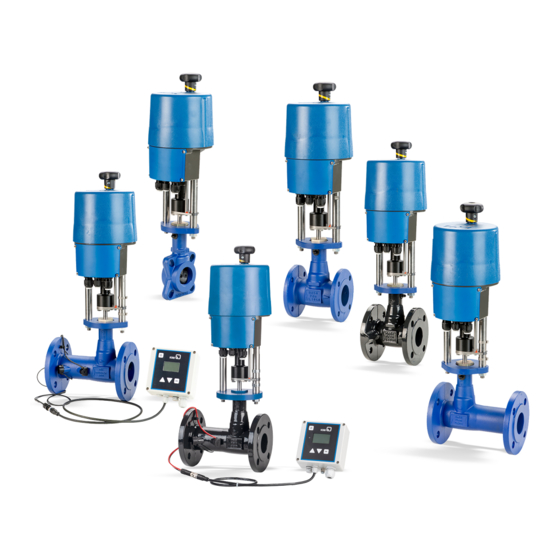
- Page 1 Control Valve Actuators EA-C / EA-B For the Type Series BOA-CVE C/CS/W/IMS/EKB/IMS EKB Installation/Operating Manual...
- Page 2 All rights reserved. The contents provided herein must neither be distributed, copied, reproduced, edited or processed for any other purpose, nor otherwise transmitted, published or made available to a third party without the manufacturer's express written consent. Subject to technical modification without prior notice. © KSB SE & Co. KGaA, Frankenthal 09/09/2020...
-
Page 3: Table Of Contents
Contents Contents General.............................. 5 Principles ................................ 5 Target group.............................. 5 Symbols ................................ 5 Safety .............................. 6 Key to safety symbols/markings........................ 6 General................................ 6 Intended use .............................. 7 2.3.1 Prevention of foreseeable misuse....................... 7 Personnel qualification and training....................... 7 Consequences and risks caused by non-compliance with this operating manual........ 7 Safety awareness .............................. 7 Safety information for the user/operator ....................... 8 Safety information for maintenance, inspection and installation .............. 8... - Page 4 Contents 6.3.1 Ambient temperature........................ 28 Shutdown................................ 29 6.4.1 Measures to be taken for shutdown .................... 29 Returning to service ............................ 29 Servicing/Maintenance ........................ 30 Safety regulations............................ 30 Removing the actuator .......................... 30 7.2.1 Removing type EA-B12 ........................ 30 7.2.2 Removing type EA-C 20 to 140...................... 31 Maintenance/inspection.......................... 32 Lubrication .............................. 32 Cleaning ................................ 32 Mounting the actuator .......................... 32 Spare parts stock............................. 32...
-
Page 5: General
The order number and order item number uniquely identify the valve and actuator and serve as identification for all further business processes. In the event of damage, immediately contact your nearest KSB service facility to maintain the right to claim under warranty. 1.2 Target group This operating manual is aimed at the target group of trained and qualified specialist technical personnel. -
Page 6: Safety
2 Safety 2 Safety All the information contained in this section refers to hazardous situations. DANGER In addition to the present general safety information the action-related safety information given in the other sections must be observed. 2.1 Key to safety symbols/markings Table 2: Definition of safety symbols/markings Symbol Description... -
Page 7: Intended Use
2 Safety ▪ The operator is responsible for ensuring compliance with all local regulations not taken into account. ▪ The motor has been designed and constructed in accordance with the requirements of Directive 2014/35/EU (“Low-voltage Directive”). The motor is intended for use in industrial plants. ▪... -
Page 8: Safety Information For The User/Operator
2 Safety 2.7 Safety information for the user/operator ▪ Fit protective equipment (e.g. contact guards) supplied by the operator for hot, cold or moving parts, and check that the equipment functions properly. ▪ Do not remove any protective equipment (e.g. contact guards) during operation. ▪... -
Page 9: Transport/Storage/Disposal
1. On transfer of goods, check each packaging unit for damage. 2. In the event of in-transit damage, assess the exact damage, document it and notify KSB or the supplying dealer and the insurer about the damage in writing immediately. -
Page 10: Description
4 Description 4 Description 4.1 General description ▪ Electric actuator for the automation of a control valve The electric actuators are installed in industrial plants and power plants for actuating control valves and shut-off valves. They provide high actuating forces at short actuating times. -
Page 11: Design Details
4 Description Auftrag / Pos.: BOA-CVE CS 2120000000 / 0000 order No. / pos.: Kennlinie: Stellkraft: Hub: lin. 1200 N 23 mm 6/10/16 characteristic: act. force: stroke: IP54 Stromversorgung: Laufzeit: Signal: Antrieb: 150 s 2 - - 10 V EA- -B12/24 power supply: run time: signal:... -
Page 12: Function
4 Description Design Type EA-B Type EA-C ▪ Configurable, microprocessor-controlled actuators – Supply voltage: 24 V AC/DC, 230 V AC – Position setpoint: 4 - 20 mA, 0/2 - 10 V – Actual-position feedback: 4 - 20 mA, 0/2 - 10 V – Limit switching is torque-dependent in closing direction and stroke- dependent in opening direction. -
Page 13: Noise Characteristics
4 Description 4.6 Noise characteristics The sound pressure level depends on the local conditions and the duty point. The value is ≤ 35 dB(A) for EA-B and ≤ 70 dB(A) for EA-C. EA-C / EA-B 13 of 48... -
Page 14: Installation
5 Installation 5 Installation 5.1 General information/Safety regulations DANGER Electrical connection work by unqualified personnel Danger of death from electric shock! ▷ Always have the electrical connections installed by a trained and qualified electrician. ▷ Observe regulations IEC 60364. DANGER Work performed on an energised terminal box Danger of death from electric shock! ▷... -
Page 15: Checking Prior To Installation
5 Installation 5.2 Checking prior to installation Before beginning with the installation check the following: ▪ The actuator and valve are compatible. ▪ The valve has been prepared for the actuator to be mounted. ▪ The actuator cover has been removed if necessary. –... -
Page 16: Manual Override
5 Installation Fig. 3: Installation position depending on actuator type Actuator type EA-B 12 Actuator types EA-C 20 to EA-C 140 and EA-C 3-point Install the actuator with sufficient clearance for removal. (ð Section 5.2, Page 15) 5.4 Manual override A handwheel (actuator type EA-C) or hexagon socket (actuator type EA-B) is provided for operating the actuator in the event of a power failure or for making settings when mounting the actuator on the valve. -
Page 17: Mounting Actuator Type Ea-B 12
5 Installation CAUTION Manual operation of actuator Damage to the actuator and the valve! ▷ Do not operate the actuator manually when the motor is in the electric actuation mode. The actuator will try to compensate for the deviation in position, depending on the actuation mode. -
Page 18: Electrical Connection
5 Installation 6. Slide the locking device (10) down again until it will not go any further, locking the connection between the coupling (7) and the valve stem (9). 7. Position the tabs of the position indicator (8) such that they abut the coupling (7). - Page 19 5 Installation EA-C / EA-B 19 of 48...
-
Page 20: Mounting Actuator Type Ea-C 20 To 140
5 Installation 5.6 Mounting actuator type EA-C 20 to 140 5.6.1 Fitting the actuator ü The actuator has been de-energised. ü The actuator is in the middle position. 1. Unscrew the four hexagon head bolts (7) from the actuator coupling. 2. Slide the coupling disc (5) over the end of the stem (6). 3. -
Page 21: Electrical Connection
5 Installation 5.6.2 Electrical connection DANGER Electrical connection work by unqualified personnel Danger of death from electric shock! ▷ Always have the electrical connections installed by a trained and qualified electrician. ▷ Observe regulations IEC 60364. DANGER Work performed on an energised terminal box Danger of death from electric shock! ▷... - Page 22 5 Installation 6. Mechanically secure the power cable and control cable before the terminals to prevent loosening. 7. Tighten the cable gland. 8. Mount the terminal box cover and fasten it with screws. ð Only tighten the screws until resistance can be felt. Terminal box under the actuator cover (handwheel on top - on 230 V and 400 V 3- point actuators) ü...
-
Page 23: Mains Connection
5 Installation 5.6.3 Mains connection DANGER Unintentional contact with live parts Danger of death from electric shock! ▷ De-energise the mains connection. ▷ Take steps to ensure that the mains connection cannot be re-energised unintentionally. CAUTION Improper electrical connection Damage to the actuator! ▷... -
Page 24: Heating Resistor (Optional)
5 Installation Actual process value for process controller (optional) Terminals 15 to 17 serve to connect the parameterisable actual process value via 4-20 mA 15 16 17 or 0/2-10 V signals supplied by the process sensor, if the optional process controller in the actuator is used. -
Page 25: Limit Switching
5 Installation The heating resistor inside the actuator is powered by the actuator's power supply, i.e. separate mains connection is not required. When retrofitting the heating resistor, connect it to the terminals on the mainboard as shown. Mount the heating resistor on the mounting plate in the position shown, using the screws supplied. -
Page 26: Operation
5 Installation ① Stem nut retracting (Open) ② Stem nut extending (Close) Locking screw Gear screw ③ ④ 5.6.7 Operation Operation status indication/ Status LEDs inside the terminal box Operating elements Inside the terminal box, a red (1) and a green (2) LED indicate the operation and fault status, respectively. -
Page 27: Commissioning/Start-Up/Shutdown
6 Commissioning/Start-up/Shutdown 6 Commissioning/Start-up/Shutdown 6.1 Prerequisites for commissioning/start-up NOTE Never operate the actuator electrically or pneumatically before it has been mounted onto a valve. Before commissioning/starting up the drive, make sure the following conditions are met: ▪ The actuator has been properly mounted and aligned. ▪... -
Page 28: Mechanical Commissioning Of 3-Point Actuators
6 Commissioning/Start-up/Shutdown Fig. 11: Commissioning button and LEDs 1 Commissioning button 2 Green LED 3 Red LED ü Check whether the terminal box cover or the actuator cover needs to be removed, see the selection table. 1. Remove the terminal box cover or the actuator cover, depending on the design. (ð Section 5.6.2, Page 21) 2. -
Page 29: Shutdown
6 Commissioning/Start-up/Shutdown 6.4 Shutdown 6.4.1 Measures to be taken for shutdown 1. Disconnect the equipment from the power supply. ð If a power back-up unit is fitted, the stem moves into the set limit position. 2. Secure against unauthorised start-up. ð... -
Page 30: Servicing/Maintenance
NOTE All maintenance work, service work and installation work can be carried out by KSB Service or authorised workshops. For contact details please refer to the enclosed "Addresses" booklet or visit "www.ksb.com/contact" on the Internet. -
Page 31: Removing Type Ea-C 20 To 140
7 Servicing/Maintenance Actuator spindle Spacer ring Actuating bush Fastening nut Bracket Clamping hoop Coupling Position indicator Valve stem Locking device Latches 7.2.2 Removing type EA-C 20 to 140 Fig. 12: Removing actuator type EA-C 20 to 140 Coupling Coupling nut Tensioning screw Screwed insert Pillar Stem... -
Page 32: Maintenance/Inspection
7 Servicing/Maintenance Top flange Pillar nut ü The actuator has been de-energised. ü The power back-up unit of continuous-action actuators has been disconnected separately. 1. Depending on the actuator, remove the actuator cover or terminal box cover. (ð Section 5.6.2, Page 21) 2. Disconnect the power cable and the control cable from the terminals. 3. -
Page 33: Trouble-Shooting
If problems occur that are not described in the following table, consultation with the KSB service is required. Faults are indicated by a green and a red LED inside the terminal box. To see the display, the terminal box cover or actuator cover must be removed, depending on the design. - Page 34 8 Trouble-shooting A B C D E F G H Status Possible cause Remedy - - - ✘ - - - ✘ Actuator does not respond; Voltage supplied does not Apply correct supply voltage. both status LEDs are off. match the supply voltage indicated on the name plate.
- Page 35 Check mains connection. the actuator Supply voltage fluctuations Check power supply. See data sheet Insufficient voltage supplied Contact KSB Service. by rechargeable battery (on actuator options with "accupack" rechargeable battery pack) Table 13: Trouble-shooting actuator faults A B C D E F G H Actuator fault...
-
Page 36: Related Documents
9 Related Documents 9 Related Documents 9.1 General assembly drawing, manual override EA-B 12 Fig. 13: General assembly drawing, manual override EA-B 12 Table 14: List of components Part No. Description Material Hexagon socket for manual Metal override Actuator cover Plastic Coupling Plastic EA-C / EA-B 36 of 48... -
Page 37: General Assembly Drawing, Handwheel On Top (Ea-C 20 To 140)
9 Related Documents 9.2 General assembly drawing, handwheel on top (EA-C 20 to 140) Fig. 14: General assembly drawing, handwheel on top (EA-C 20 to 140) Table 15: List of components Part No. Description Material Handwheel Plastic Actuator cover Plastic/Aluminium Terminal box cover Plastic Pillars Steel... -
Page 38: Wiring Diagrams
9 Related Documents 9.3 Wiring diagrams 9.3.1 Terminal configuration EA-B 10/24 Table 16: Continuous-action actuation Controller EA-B12 24 V 24 V AC DC 0 ... 10 V DC 2 ... 10 V DC 4 ... 20 mA Wiring diagram EA-B 10/24 Table 17: 3-point actuation 3-point actuation 24 V (Ground for Y1, Y2 and U) 24 V... -
Page 39: Terminal Configuration Ea-C 20 To 140, 230 V Ac
9 Related Documents 9.3.3 Terminal configuration EA-C 20 to 140, 230 V AC Table 20: Continuous-action actuation, 230 V AC 10 11 12 13 14 15 16 17 18 19 20 21 22 23 RJ-45 Push- butto ↑ ↑ ↑ ↓ ↓ ↓ ↑↓ ↑↓ ↑ ↑... - Page 40 9 Related Documents X5/1 Neutral X5/2 Motor phase to open X5/4 Motor phase to close X5/6 and X5/7 Thermal switch as volt-free contact Additional limit switches Not used Heating resistor Potentiometer 2 Earth connection on housing Terminal configuration of power supply Terminal configuration of additional limit switches Closed...
-
Page 41: Technical Data
7520.85/01-EN 9.4 Technical data 9.4.1 Operating data: EA-B 12 actuator Table 22: Operating data of EA-B 12 actuator (24 V AC) Actuating force 1200 Stroke [mm] Handwheel turns [/10 mm stroke] 28 Actuating speed [mm/s] 0,12 - 0,22 Power supply 24 V AC 1~ Frequency [Hz] Nominal current 0,12 Max. -
Page 42: Operating Data: Ea-C 20 To 140 Actuators, 230 V Ac
EA-C 20 EA-C 40 EA-C 40 EA-C 140 Enclosure EN 60529 IP 65 IP 65 IP 65 IP 67 Permissible ambient temperature [°C] -20 to +60 Motor protection Thermal monitoring and overload protection Weight (without accessories) [kg] 9.4.3 Operating data: EA-C 20 to 140 actuators, 230 V AC Table 24: Operating data: 230 V AC, continuous-action EA-C 20 EA-C 40... - Page 43 7520.85/01-EN EA-C 20 EA-C 40 EA-C 40 EA-C 140 Nominal current 0,05 0,08 0,23 0,23 Max. power input Mode of operation IEC 60034-1,8 S2 30 min, S4 80 % ED - S2 30 min, S4 50 % ED - 1200 c/h 1200 c/h Enclosure EN 60529 IP 65 IP 65 IP 65 IP 67 Permissible ambient temperature...
-
Page 44: Eu Declaration Of Conformity
10 EU Declaration of Conformity 10 EU Declaration of Conformity Manufacturer: KSB SE & Co. KGaA Johann-Klein-Straße 9 67227 Frankenthal (Germany) The manufacturer herewith declares that the product: KSB EA-B 12, KSB EA-C 20, KSB EA-C 40, KSB EA-C 80, KSB EA-C 140, ▪ is in conformity with the provisions of the following directives / regulations as amended from time to time: –... -
Page 45: Declaration Of Incorporation Of Partly Completed Machinery
11 Declaration of Incorporation of Partly Completed Machinery 11 Declaration of Incorporation of Partly Completed Machinery Manufacturer: KSB SE & Co. KGaA Johann-Klein-Straße 9 67227 Frankenthal (Germany) The manufacturer herewith declares for the partly completed machinery: KSB EA-B 12, KSB EA-C 20, KSB EA-C 40, KSB EA-C 80, KSB EA-C 140... -
Page 46: Index
Index Index Operating status indication EA-C 20 to 140 26 Commissioning 27 Order number 5 Commissioning button Outputs EA-C 20 to 140 26 EA-C 20 to 140 24 Commissioning/start-up 27 Personnel 7 Design 12 Preservation 9 Designation 10 Disposal 9 Qualification 7 Electrical connection EA-B 12 27 Safety 6 Event of damage 5 Safety awareness 7 Specialist personnel 7 Faults Storage 9 Causes and remedies 33... - Page 48 KSB SE & Co. KGaA Johann-Klein-Straße 9 • 67227 Frankenthal (Germany) Tel. +49 6233 86-0 www.ksb.com...
Need help?
Do you have a question about the EA-C Series and is the answer not in the manual?
Questions and answers