Table of Contents
Advertisement
Quick Links
Advertisement
Table of Contents

Related Manuals for RGBlink RGB-RD-UM-M2 E003


Summary of Contents for RGBlink RGB-RD-UM-M2 E003
- Page 1 USER MANUAL Article No: RGB-RD-UM-M2 E003 Revision No: V1.3 User Manual...
-
Page 2: Table Of Contents
CONTENTS CONTENTS................................ 2 Declarations..............................4 FCC/Warranty............................4 Operators Safety Summary........................5 Installation Safety Summary........................5 Chapter 1 Your Product............................ 1 1.1 In the Box............................1 1.2 Product Overview..........................2 1.2.1 Rear Panel..........................3 1.2.2Front Panel..........................5 1.2.3 Dimension..........................10 Chapter 2 Installing Your Product........................11 2.1 Plugging in Signals..........................11 2.2 Plugging in Main Power........................ - Page 3 3.5.2 4K1K............................35 3.5.3 4K2K............................41 3.5.4 Matrix............................42 3.5.5 Presentation..........................43 3.6 Switching Layers..........................45 3.7 Background Picture..........................47 3.7.1 Input Source..........................47 3.7.2 Captured Picture........................47 3.7.3 Picture file loaded with U Disk..................... 48 3.8 Set the Output Resolution....................... 52 3.8.1 Select the Output Resolution....................52 3.8.2 Custom the Output Resolution.....................52 3.9 Using Black Out..........................
-
Page 4: Declarations
RGBlink. If the purchaser or a third party carries out modifications or repairs on goods delivered by RGBlink, or if the goods are handled incorrectly, in particular if the systems are commissioned operated incorrectly or if, after the transfer of risks, the goods are subject to influences not agreed upon in the contract, all guarantee claims of the purchaser will be rendered invalid. -
Page 5: Operators Safety Summary
Operators Safety Summary The general safety information in this summary is for operating personnel. Do Not Remove Covers or Panels There are no user-serviceable parts within the unit. Removal of the top cover will expose dangerous voltages. To avoid personal injury, do not remove the top cover. Do not operate the unit without the cover installed. - Page 6 shipping carrier immediately for all claims adjustments. As you open the box, compare its contents against the packing slip. If you find any shortages, contact your sales representative. Once you have removed all the components from their packaging and checked that all the listed components are present, visually inspect the system to ensure there was no damage during shipping.
-
Page 7: Chapter 1 Your Product
Chapter 1 Your Product 1.1 In the Box Power Cord CAT5E HDMI to DVI Cable Screw Driver Anti-static Bag Note: The USB file contains Warranty/Registration Card. AC Power Cord supplied as standard according to the destination market. -
Page 8: Product Overview
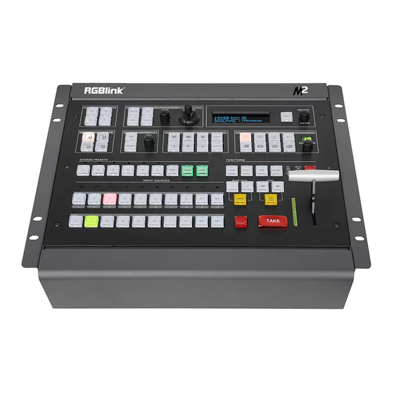
Chapter 1: Your Product 1.2 Product Overview All-in-one scaling and mixing just got even better. Now you choose input options, now you configure output operations, now control transitions from the T-bar, now apply layer masks, now do more. M2 redefines modern hands-on scaling and mixing for any environment. Totally modular and flexible in configuration, M2 is packed with standard features to impress and present with ease. -
Page 9: Rear Panel
Chapter 1: Your Product 1.2.1 Rear Panel Input Option Slots M2 provides 3 slots to hold 9 single input module options including DVI, VGA, HDMI, USB, CVBS, DP and SDI. DVI-I Each DVI module has one DVI-I input, which can be connected to signals with DVI port. - Page 10 Chapter 1: Your Product connected to the next M2 or the device with SDI input. PGM Output HDMI 2. 3 Connect to the display or the LED screen with HDMI connector or patch cord (HDMI to DVI). PST Output HDMI Connect to the display with HDMI connector to preset the views.
-
Page 11: 2Front Panel
Chapter 1: Your Product 1.2.2Front Panel Panel Instruction Layer adjustment buttons MASK buttons Layer selection buttons Transition buttons Layer effect buttons Functions buttons Multiview presets buttons Independent effects switching buttons Stored presets buttons OSD edit buttons Input source buttons Switchers Menu button and OLED display Layer Adjustment Buttons SCALE... - Page 12 Chapter 1: Your Product FREEZE Freeze the image or video. Rotary Knob For dimension and position adjustment and confirmation. Press SCALE button and control the rotary knob to adjust the dimensions. Press POS button and control the rotary knob to adjust the positions. Joystick For size and position adjustment.
- Page 13 Chapter 1: Your Product PAGE For saving or loading, 6 pages in total, and 6 banks for each page. 1/2/3/4/5/6 These buttons can be used for numeric entry when SAVE or LOAD button is pressed. Input Source Buttons LED Indicator The button 1/2/3/4/5/6/7/8 is lit when the signal or background input is available.
- Page 14 Chapter 1: Your Product : Crescent Left : Star : Diamond CUS1/CUS2 Mask custom button. Press any mask button, it will enter to the layer mask setting menus. Select the layer, and set the Mask & PIC Pos X and Y, or set Mask Pos X, Y of Mask or PIC separately. User can also load file from U Disk.
- Page 15 Chapter 1: Your Product file from U Disk. BLACK The button is lit when BLACK function is enabled. BLACK is available for PGM channel only. Refer to Using Black Out. LOCK Lock all buttons on top panel. The button is lit when the buttons on top panel are locked. Press the button again, the button light is off, and the buttons are unlocked.
-
Page 16: Dimension
Chapter 1: Your Product 1.2.3 Dimension... -
Page 17: Chapter 2 Installing Your Product
Chapter 2: Installing Your Product Chapter 2 Installing Your Product 2.1 Plugging in Signals Connect signals to the product (ensure all devices are powered off first). Tighten connector screws/locks where provided. 2.2 Plugging in Main Power Connect IEC cable to device and plug into wall socket. Turn on power at wall socket. 2.3 Turning on Your Product Turn on the power switch on the rear panel. - Page 18 Chapter 2: Installing Your Product PST Input : HDMI Output Format: 1920×1080@60 System Mode: Normal SN: 0019 Version: 1.59...
-
Page 19: Chapter 3 Using Your Product
Chapter 3 Using Your Product 3.1 Using the MENU Button Press the MENU button to display the main menu. Turn the rotary knob to navigate to the menu item required. If an item is selected, its background turns green. Press the knob to confirm the selection, and set the parameters or check information. -
Page 20: Understanding The Menu Structure
Chapter 3: Using Your Product 3.2 Understanding the MENU Structure The MENU structure is shown in the figure below:... -
Page 21: Using The Menu
Chapter 3: Using Your Product 3.3 Using the Menu Use the menu system for convenient and intuitive operation. M2 OLED display shows the menu items. The OLED display will show the default state when the menu is not in use, or the operation has timed out. -
Page 22: Understanding The Main Menu
Chapter 3: Using Your Product 3.3.2 Understanding the Main Menu Press the MENU button in the default state and turn the rotary knob, the OLED display will show the main menus as below: ->Input >> Output >> Background >> Advance >>... -
Page 23: Output Menu
Chapter 3: Using Your Product If VGA is selected, user can enable or disable Auto Adjust and set Pos X, Pos Y, Clock and Phase. 3.3.4 Output Menu ->Format 1920×1080@60 Custom Format >> System Mode >> Color Space/Sample/Bit >> ->External Sync >>... -
Page 24: Background Menu
Chapter 3: Using Your Product Range: 0~255. Green Range: 0~255. Blue Range: 0~255. 3.3.5 Background Menu ->Background 1 File 1 Background 1 File 2 Background 1/2 Picture Picture File 1~14 can be selected. Load from U Disk Background 1/2 Whether to load file from U Disk. Delete Delete the selected file. - Page 25 Chapter 3: Using Your Product Set the horizontal position of the LOGO. Set the vertical position of the LOGO. Delete Delete the selected LOGO. Load File From U Disk Load file from U Disk. ON/OFF Enable or disable the OSD function. Delete Delete the OSD.
- Page 26 Chapter 3: Using Your Product Delete Delete the still. Load File From U Disk Load a file from U Disk. Layer Select the layer. Blending Width Blending Set the blending width, the adjustment range is between 1~90. ON/OFF Enable or disable the Blending function. Layer Select the layer.
-
Page 27: Language Menu
Chapter 3: Using Your Product 3.3.7 Language Menu ->Language/语言 English Language/语言 Select Chinese or English. 3.3.8 System Menu Version >> Ethernet >> T-BAR Calibration >> Key Board Test Fan Control >> ->Take Mode Swap Show the version of COM, PVW MCU, PVW FPGA, PST+PGM MCU, PST+PGM FPGA, Optional In 1 MCU, Optional In 1-1 Video, Optional In Version 1-2 Video, Optional In 1-3 Video, Optional In 2 MCU, Optional In 2-1... -
Page 28: Factory Reset Menu
Chapter 3: Using Your Product 3.3.9 Factory Reset Menu ->Factory Reset >> Factory Reset, Save IP >> Factory Reset Select “YES” or “NO”. Select “YES” to restore default settings. Factory Reset, Select “YES” or “NO”. Select “YES” to restore default settings, but the IP Save IP information remains unchanged after reset. -
Page 29: Pst Mode
Chapter 3: Using Your Product 3.4 PST Mode M2 can be connected to 2 preview displays with HDMI connectors, and the preview has the functions as below: 3.4.1 Signal Selection Press any button in Input Sources Area, for example, Press the button [5], the button is lit (yellow), and the signal in PGM monitor will be changed to signal 5. - Page 30 Chapter 3: Using Your Product - Press the lit button in PGM area. The layers in PGM are also displayed in PST, synchronously; - Select layer [A] or [B]; - Press the FREEZE button, the selected layer is frozen in both PST and PGM displays, synchronously;...
-
Page 31: Multiview Presets
Chapter 3: Using Your Product 3.4.4 Multiview Presets 1. Press any button in Multiview Presets Area to select multiview layouts, including 1P, PIP CENT, and 3P. 2. User can adjust the position, dimension for the selected layer, and set DSK, BLEND and MASK. 3.4.5 Set the Position 1. -
Page 32: Scale And Crop The Layer
Chapter 3: Using Your Product 3.4.6 Scale and Crop the Layer 1. Press any button of [A] to [D] in Layer Selection Area, the light flashes when the layer is selected. 2. Press the SCALE button in Layer Adjustment Area, and enter to the menus as follows: ->H Size 1920 V Size... -
Page 33: Dsk Settings
Chapter 3: Using Your Product 3.4.7 DSK Settings 1. Firstly, enable the multiview function. DSK is used in multiview only. 2. Press MENU button, and enter to the menu items. Turn the rotary knob, and select <DSK> option in <Advance>, Press the knob to confirm. (Or Press the DSK button to enter to the DSK menu items) ->Layer Layer 1... - Page 34 Chapter 3: Using Your Product Key Out The color selected in [Preset] remains unchanged and other colors are cut out. Take Black Background and Blue Background for example, see the effect below: User In addition, User can select [User] in [Preset], which allows user to custom the color value by setting Red Min, Red Max, Green Min, Green Max, Blue Min and Blue Max values.
-
Page 35: Blend Settings
Chapter 3: Using Your Product 3.4.8 BLEND Settings 1. Firstly, enable the multiview function. 2. Press MENU button, and enter to the menu items. Turn the rotary knob, and select <Blending> option in <Advance>, Press the knob to confirm. (Or Press the BLEND button to enter to the BLEND menu items) ->Layer Layer 1... -
Page 36: Mask Settings
Chapter 3: Using Your Product 3.4.9 Mask Settings 1. Press the MENU button, and enter to the menu items. 2. Turn the rotary knob, and select <Mask> option in <Advance>, Press the knob to confirm: ->Mask Heart Layer Layer 1 ON/OFF Set Mask&PIC Pos X together ->Set Mask&PIC Pos Y together... - Page 37 Chapter 3: Using Your Product Mask settings: The MASK shortcut button can be used as a shortcut button to enlarge the mask. For each MASK button, 6 dimensions are available. Press a shortcut button, press it again and the mask will be enlarged.
-
Page 38: Transition Settings
Chapter 3: Using Your Product ->Custom 1 Star Layer Layer 1 ON/OFF Mask&PIC Pox X Set a Mask: User can set the H position, V position, H size, V size of Mask and/or PIC. In addition, user can load custom masks by U Disk. Refer to the Custom EFFECT. -
Page 39: Adjust R,G,B Of Sdi,Vga,Cvbs,Usb Input
Chapter 3: Using Your Product 3.4.11 Adjust R,G,B of SDI,VGA,CVBS,USB Input M2 of Version 2.13 allows users to adjust the value of RGB of SDI,VGA,CVBS,USB input. PST Input :VGA Output Format:1920x1080@60 System Mode : Normal SN:0229 Version:2.13 Here are the operation. Enter Menu of Input ->Input >>... - Page 40 Chapter 3: Using Your Product COLOR TEMP BLUE Reset Brightness R,G,B Value range from 0 to 100 Contrast range from 0 to 100 Saturation rang from 0 to 100 Sharpness range from 0 to100 Color Temp R,G,B value range from 0 to 255...
-
Page 41: System Mode
Chapter 3: Using Your Product 3.5 System Mode 3.5.1 Normal (1) Press the MENU button and enter to the menu items. Turn the knob and select <OUTPUT>: Input >> Output >> Background >> Advance >> (2) Press the knob to confirm. Turn the knob, select <Normal> and press the knob to confirm: Format >>... - Page 42 Chapter 3: Using Your Product (1) Press MENU button, enter to the menu items. Turn the knob and select <Output>: Input >> ->Output >> Background >> Advance >> (2) Press the knob to confirm. Select <4K1K> under <System Mode>. Press the knob to confirm: ->Normal Mode >>...
- Page 43 Chapter 3: Using Your Product When <Two Inputs Two Outputs> is selected, [A] and [B] are background layers, [C] and [D] are sublayers. In the right mode, when <One Input Two Outputs> is selected, [A] is the background layer, [C] is the sublayer, [B] and [D] have no function.
- Page 44 Chapter 3: Using Your Product Normal Mode >> ->Overlayer >> (4) Set the overlayer width (for example, 200), select <Start Quick Start Mode> and press the knob to confirm: ->Overlayer Start Quick Start Mode >> Note: Overlayer width refers to the width of the overlapped part of two layers (two ports). (5) Select a background layout mode: In Layout 1, when <One Input Two Outputs>...
- Page 45 Chapter 3: Using Your Product In Layout 2, when <One Input Two Outputs> is selected, the overlapped part is as below: When <Two Inputs Two Outputs> is selected, the overlapped part is as below: In Layout 3, when <One Input Two Outputs> is selected, the overlapped part is as below: When <Two Inputs Two Outputs>...
- Page 46 Chapter 3: Using Your Product...
-
Page 47: 4K2K
Chapter 3: Using Your Product 3.5.3 4K2K (1) Press the MENU button, enter to the main menu. Turn the knob and select <Output>: Input >> ->Output >> Background >> Advance >> (2) Press the knob to confirm. Turn the knob, select <4K2K> under <System Mode>, press the knob to confirm: Normal >>... -
Page 48: Matrix
Chapter 3: Using Your Product 3.5.4 Matrix (1) Press the MENU button, enter to the main menu. Turn the knob and select <Output>: Input >> ->Output >> Background >> Advance >> (2) Press the knob to confirm. Turn the knob, select <Matrix> under <System Mode>, press the knob to confirm: Normal >>... -
Page 49: Presentation
Chapter 3: Using Your Product 3.5.5 Presentation (1) Press the MENU button, enter to the main menu. Turn the knob and select <Output>: (2) Press the knob to confirm. Turn the knob, select <Presentation> under <System Mode>, press the knob to confirm: 4K1K >>... - Page 50 Chapter 3: Using Your Product (5)Presentation Group mode allows PGM1 and PGM2 to be switched at the same time. Layers A,B,C are on PST1 and Layer D on PST2. When PST1 is selected, users can change the input source and layout of Layer A,B,C and switch to PGM1 by TAKE button or T-Bar. When PST2 is selected, users can change input source and layout of Layer D and switch to PGM2 by TAKE or T-Bar .Under the Presentation Group mode, PST1 and PST2 are switched to PGM1 and PGM2 by TAKE button at the same time.
-
Page 51: Switching Layers
Chapter 3: Using Your Product 3.6 Switching Layers User can use T-bar, CUT or TAKE to switch layers between PGM and PST. T-bar: Switch the PST layer PST to PGM; user can set the transition duration. The transition effect can be paused or played back by pushing T-bar. CUT: Quick seamless transition. - Page 52 Chapter 3: Using Your Product After Switching If STAY is selected, the PST layer and PGM layer are the same even after pressing the CUT, TAKE button or using T-bar. The PST layer can be edited independently. After another switch, the PGM layer is the same with PST layer.
-
Page 53: Background Picture
Chapter 3: Using Your Product 3.7 Background Picture 3 sources can be used as the background picture of M2, they are input source, captured picture, and picture file loaded with U Disk. 3.7.1 Input Source User can use an input source as the background picture. For example, user can connect the device to a computer, and the current input can be used as the background. -
Page 54: Picture File Loaded With U Disk
Chapter 3: Using Your Product Background 1 Picture ->Picture File 1 Load from U Disk No U Disk Delete 3.7.3 Picture file loaded with U Disk The background picture can be a picture loaded with U Disk. See below: Before loading a picture: The maximum resolution is 1920×1080;... - Page 55 Chapter 3: Using Your Product (5) Click OK, a dialog reading “The new canvas size is smaller than the current canvas; some clipping will occur” will pop up. Click PROCEED. (6) Save the two halves as BMP pictures, and name them as IMAGE_1 and IMAGE_2 respectively.
- Page 56 Chapter 3: Using Your Product (3) Press the BK1 or BK2 in the PST area, and select Background 1→File 1 or Background 2→File 2. Save the settings. If the resolution does not meet the criteria. For example, the required resolution is 3800×1000. Follow the steps as below: (1) Press the MENU button, select <Output>: Input...
- Page 57 Chapter 3: Using Your Product (6) Press the BK1 or BK2 in the PST area, and select Background 1 File 1 or Background 2 File 2. Save the settings.
-
Page 58: Set The Output Resolution
Chapter 3: Using Your Product 3.8 Set the Output Resolution 3.8.1 Select the Output Resolution 1. Press the MENU button, and enter to the menu items, turn the rotary knob and select <Output>: Input >> ->Output >> Background >> Advance >>... - Page 59 Chapter 3: Using Your Product Format 1920×1080@60 ->Custom Format >> 4K1K >> Color Space/Sample/Bit >> ↓ ->H Active 1024 V Active Freq 4. Set H Active, V Active and Fred according to actual need, then select <Set> and set “Yes”, Press the rotary knob to confirm.
-
Page 60: Using Black Out
Chapter 3: Using Your Product 3.9 Using Black Out Black out description: One-key touch to black out the display M2 provides BLACK effect processing for PGM and PST, with instant BLACK effect. Operation is as below: Press the BLACK button, the button light is lit, and the PGM display is blacked out. The effect is shown as below:... -
Page 61: Saving Views
Chapter 3 : Using Your Product 3.10 Saving Views M2 provides 36 banks for saving or recording parameters. To save the current parameters and settings: 1. Press the SAVE button in Stored Presets Area, the SAVE and PAGE button lights are lit, and some of buttons 1~6 are lit and some are flashing. -
Page 62: Recall Saved Settings
Chapter 3: Using Your Product 3.11 Recall Saved Settings M2 provides 36 banks for saving or recording parameters. To recall saved settings: 1. Press the LOAD button in Stored Presets Area, the button lights of LOAD and PAGE are lit, and some of buttons 1~6 are lit and some are flashing. -
Page 63: Chapter 4 Ordering Codes
Chapter 4 Ordering Codes 4.1 Product 210-3072-02-0 4.2 Options 4.2.1 Input Options 190-0001-02-1 VGA Input 1× VGA 190-0001-03-1 Display Port Input (DP1.0) 1 × Display Port 190-0001-04-1 DVI Input 1 × DVI 190-0001-06-1 HDMI Input /Loop Out 1 × HDMI (with loop) 190-0001-07-1 3G-SDI Input /Loop Out 1 ×... -
Page 64: Chapter 5 Support
Chapter 5 Support 5.1 Contact Us... -
Page 65: Chapter 6 Appendix
Chapter 6 Appendix 6.1 Specification DVI Input (DVI optional module) Interface Appearance Board Size 52(L)×19.5(W) (mm) Number of Inputs Connector Standard DVI-I socket Supported Resolution SMPTE: 625/25/50 PAL, 525/29.97/59.94 NTSC, 1080P50/59.94/60, 720p50/59.94/60 VESA: 800×600@60 | 1024×768@60 | 1280×1024@60 | 1600×1200@60 | 1920×1080@60 | 1920×1200@60 | 2048×1152@60 Signal Level TMDS pwl, single pixel input,165MHz bandwidth Format Standard... - Page 66 Format Standard DP1.0 CVBS Input (CVBS optional module) Interface Appearance Board Size 52(L)×19.5(W) (mm) Number of Inputs Connector Standard BNC Socket Supported Standards PAL/NTSC Signal Level 1Vpp±3db (0.7V Video+0.3v Sync) 75 ohm Multiplex 480i, 576i USB Input (USB optional module) Interface Appearance Board Size 52(L)×19.5(W) (mm)
- Page 67 Connector Standard BNC Socket Data Rate 2.97Gb/s, 2.97/1.001Gb/s, 1.485Gb/s, 1.485/1.001Gb/s and 270Mb/s Supported Standard SMPTE 425M - 3G Level A and Level B SMPTE 425M (3G Level A) 4:2:2: 1920×1080/60 (1:1) | 1920×1080/50 (1:1). SMPTE 425M (3G Level B DS1 and DS2) 4:2:2: 1920×1080/60 (2:1) | 1920×1080/50 (2:1) Supported Resolution SMPTE 296M (HD): 1280×720/50 (1:1) | 1280×720/50 (1:1)
- Page 68 Supported Resolution SMPTE: 625/25 PAL, 525/29.97 NTSC, 625/50p PAL, 525/59.94p NTSC, 720p50/59.94/60 | 1080i50/59.94/60 | 1080P50/59.94/60 VESA: 800×600@60 | 1024×768@60 | 1280×768@60 | 1280×1024@60 | 1600×1200@60 | 1920×1080@60 | 1920×1080@50 Format Standard HDMI 1.3 HDMI PST Output Number of outputs Connector HDMI standard type A interface Supported Resolution...
- Page 69 TALLY Pin Definition PIN9 NC (No Connection) avoid to be plugged by VGA connector Function Switch Support any two inputs fade in fade out Extras Communication USB/TCP/IP Power Supply 85-264V, IEC-3 Working Environment 0°C~45°C Stored Environment 10% to 90% Product Warranty 3 years parts and labor warranty...
-
Page 70: Upgrade
Chapter 6: Appendix 6.2 Upgrade RGBLink provide firmware package for M2 device update on our website. Please use the following link to Downloads category of M2 on our website. https://www.rgblink.com/product-detail?id=713 1.Enter the web page and scroll down, Downloads will be seen 2.Download the latest released M2 Firmware.ZIP... - Page 71 Chapter 6: Appendix In Upgrade tool there are latest released XTOOL_EN_V1.0.0.32_20180921 for Window and Mac separately For easier upgrade of M2 we suggest USB upgrade as the Upgrade Guide. We aslo suggest you install XTOOL for other use.
-
Page 72: Custom Osd,Mask,Logo,Still By Xtool
6.3 Custom OSD,MASK,LOGO,STILL by XTOOL XTOOL is not only used to upgrade M2 and other RGBLink products, it is also used to make files of OSD,Effect Change, Logo and STILL for M2. The files can be saved to the USB disk, and be loaded after custom the OSD, MASK, LOGO and STILL. - Page 73 Chapter 6: Appendix Click “Next” to install: Select “Browse...” to select the XTOOL software install location: Note: User should get the rights in “Roles Management” when install the software to disk C for Windows 7 or Windows 10. (Install as Administrator) If user installs the XTOOL software on Windows 10, the installation should be operated under...
- Page 74 Chapter 6: Appendix English directory. Click “Install”: During installation, it will pop up the window of InstallShield Wizard for Virtual Com port: If user installs the XTOOL software for the first time, click “Next”:...
- Page 75 Chapter 6: Appendix Then click “Install", as shown in the figure below: Click “Finish” and complete the installation, as shown in the figure below:...
- Page 76 Chapter 6: Appendix Then it will pop up the window of installation wizard for device driver, click “Next” to complete the installation. If user have installed the XTOOL software before, click “Cancel”, and it will pop up the window as below: Click “Yes”...
- Page 77 Chapter 6: Appendix Then it will pop up the window of installation wizard for device driver, click “Cancel” to exit the installation. Click “Finish” and is ready to run the XTOOL software:...
-
Page 78: Custom Osd
Chapter 6: Appendix 6.3.2 Custom OSD Double click the icon to enter to the XTOOL interface, select “Toolbox”, and enter to the window as follows: Follow the steps below: Tick OSD ON/OFF. Set the parameters as needed. Note: - Up to two lines of OSD can be displayed on a page at a time. - Page 79 Chapter 6: Appendix There are rules to follow for saving the file: The file No. should be 0~199 in order Interruption is not permitted. Save the file as M2\OSD. The format of USB should be FAT 32. - Press [OSD] button in the Functions area.
-
Page 80: Custom Effect
Chapter 6: Appendix 6.3.3 Custom Effect Select “Effect Change” in “Toolbox”, it will enter to the window as follows: First of all, user should create a graphic image with Microsoft Paint. There are some rules to follow in creating an image: The background of the image should be white by default. -
Page 81: Custom Logo
Chapter 6: Appendix 6.3.4 Custom Logo Select “Logo” in “Toolbox”, it will enter to the window as follows: First of all, user should create a graphic image with Microsoft Paint. There are some rules to follow in creating an image: The background of the image should be white by default. -
Page 82: Custom Still
Chapter 6: Appendix 6.3.5 Custom Still Select “Still” in “Toolbox”, it will enter to the window as follows: First of all, user should create a graphic image with Microsoft Paint. There are some rules to follow in creating an image: The background of the image should be white by default. -
Page 83: Terms & Definitions
Chapter 6: Appendix 6.4 Terms & Definitions The following terms and definitions are used throughout this guide. “ASCII”: American Standard for Information Interchange. The standard code consisting of 7-bit coded characters (8 bits including parity check) used to exchange information between data processing systems, data communication systems, and associated equipment. - Page 84 Chapter 6: Appendix redder the light. Benchmark color temperature for the A/V industry include 5000°K, 6500°K, and 9000°K. “Contrast ratio”: The radio of the high light output level divided by the low light output level. In theory, the contrast radio of the television system should be at least 100:1, if not 300:1. In reality, there are several limitations.
- Page 85 Chapter 6: Appendix International Standards Organization working on algorithm standards that allow digital compression, storage and transmission of moving image information such as motion video, CD-quality audio, and control data at CD-ROM bandwidth. The MPEG algorithm provides inter-frame compression of video images and can have an effective compression rate of 100:1 to 200:1.
- Page 86 Chapter 6: Appendix signal for input to an image processor, transmission path or to improve its quality when presented on a particular display. “SDI”: Serial Digital Interface. The standard based on a 270 Mbps transfer rate. This is a 10-bit, scrambled, polarity independent interface with common scrambling for both component ITU-R 601 and composite digital video and four channels of (embedded) digital audio.
-
Page 87: Revision History
Chapter 6: Appendix 6.5 Revision History The table below lists the changes to the Video Processor User Manual. Format Time ECO# Description Principal V1.0 20180201 0000# Release Linger V1.1 20190118 0001 Revise “In the Box” Fanny Add “3.5.5 Presentation” V1.2 20190306 0002 Revise “6.2 Upgrade”...
Need help?
Do you have a question about the RGB-RD-UM-M2 E003 and is the answer not in the manual?
Questions and answers