ABB UMC100.3 Manual
Univeral motor controller
Hide thumbs
Also See for UMC100.3:
- Manual (76 pages) ,
- Safety and installation instructions (2 pages) ,
- Safety and installation instructions (2 pages)
Table of Contents
Advertisement
Advertisement
Table of Contents

Related Manuals for ABB UMC100.3


Summary of Contents for ABB UMC100.3
- Page 1 — M A N UA L Univeral Motor Controller UMC100.3...
- Page 2 Device driver technology for field devices. Specified from the FDT group NC / NO Normally closed / Normally open FieldBusPlug is the name for a group of products which allows to connect ABB low voltage control products to different fieldbusses Communication Interface e.g. PDP32 for PROFIBUS —...
-
Page 3: Table Of Contents
Function Overview Compatibility to previous versions of UMC100.3 Description of Components 2 Installation Assembly and Disassembly of UMC100.3 and IO Modules Supplying the UMC and IO Modules Connecting the IO Modules DX111-FBP.0 and DX122-FBP.0 Wiring DX1xx Inputs and Outputs Connecting the VI15x Voltage Module Wiring VI15x Inputs and Outputs Connecting the AI111.0 Inputs... - Page 4 8 The LCD Control Panel UMC100-PAN Overview Monitoring Status Information and menu tree Adjusting Parameters Starting and Stopping the Motor 9 Error handling, maintenance and service Error handling of the UMC UMC100.3 fault indication Fault messages Resetting parameters to factory defaults...
- Page 5 Emergency Stop Function for Reversing Starter, Category 4 11 Technical Data UMC100.3 Tripping times Performance Data UMC100-PAN DX111-FBP.0 and DX122-FBP.0 VI150-FBP.0 and VI155-FBP.0 AI111.0 EMC UMC100.3, AI111.0, DX1xx-FBP.0 and VI15x-FBP.0 VI15x-FBP.0 Characteristic values according to IEC 61508 and ISO 13849 Dimensional drawings...
- Page 6 How to get started There are many options for using the UMC100.3. Not all functions are required in all cases. Therefore the documentation is split into separate parts. You only need to read the parts that are relevant for your application.
- Page 7 - Wrong frequency identified by voltage module VI15x-FBP.0 results in warnung only and does not trip the motor The UMC100.3 is fully backwards compatible with the previous version and replaces it. To use the new features via fieldbus new fieldbus device description files have to be used. Therefore updated GSD and EDS files are available on the ABB web site.
-
Page 8: System Overview
• Selecting the cyclically transmitted analog values by parameter Motor Management, Inputs and Outputs • The UMC100.3 provides six digital inputs, three relay outputs and one 24 V output. Therefore a wide number of control functions can be covered from the base device. - Page 9 Function Block Programming • The UMC100.3 has a set of predefined applications built in. These applications are built on the basis of function blocks and can be used directly without the need for a programming tool.
-
Page 10: Description Of Components
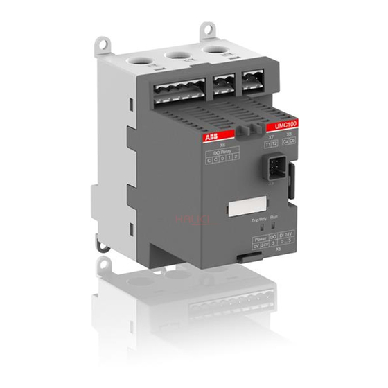
U M C 1 0 0 . 3 U N I V E R S A L M O T O R C O N T R O L L E R M A N U A L Description of Components UMC100.3 The following diagram shows the terminals, monitoring and operating elements of the UMC100.3. The UMC is shown with PDP32.0 as an example for a communication interface. Output relay... - Page 11 The starter function block controls the relay outputs depending on its input signals and the actual state. Additionally monitoring signals are prepared for the LCD display, the UMC100.3 signalling LEDs and the fieldbus monitoring and diagnosis telegrams. All these blocks run in the so-called logic engine. It is possible to change the application which is running there but usually the pre- defined applications will be sufficient.
- Page 12 U M C 1 0 0 . 3 U N I V E R S A L M O T O R C O N T R O L L E R M A N U A L DX111-FBP.0 The DX111-FBP.0 expands the input and output channels of the UMC100.3. It provides eight digital inputs for 24 V DC, four relay outputs and an analog output to drive an analogue instrument.
- Page 13 S Y S T E M O V E R V I E W VI150-FBP.0 The VI150-FBP.0 adds voltage and power protection functions to the UMC. It provides three voltage inputs and one relay output. It can be used in three- and single phase operation mode. The module can be used with grounded systems only (e.g.
- Page 14 (e.g. PT100, PT1000, NTC) or as standard signal inputs (0 - 10 V, 0/4 - 20 mA). Up to two AI111.0 modules can be connected to the UMC100.3 to offer six analog inputs in total. For the first module the ter- minal named ADR must be left open.
- Page 15 Asset Vision Basic is jointly used between ABB Instrumentation and ABB Control Products. Therefore it enables a wide range of ABB products to be configured such as motor controllers, soft starters, flow meters and many more. It is based on the FDT/DTM standard which also enables the configuration of third-party products that are connected at the same bus segment.
- Page 16 The Control Panel UMC100-PAN is an accessory for the UMC100.3 and can be used for monitoring, control and parameterisa- tion of the UMC100.3. It can be directly plugged on the UMC100.3 or mounted separately on the panel door using the mount- ing kit.
-
Page 17: Installation
Supplying the UMC and IO Modules If 24 V DC is available use the UMC100.3 DC type and connect both the UMC100.3 and the IO modules to the 24 V DC supply. If 110-240 V AC/DC is available use the UMC100.3 UC. The UMC100.3 UC provides a 24 V DC supply output. This output is intened to supply the IO modules and digital inputs with 24 V DC. -
Page 18: Wiring Dx1Xx Inputs And Outputs
U M C 1 0 0 . 3 U N I V E R S A L M O T O R C O N T R O L L E R T E C H N I C A L D E S C R I P T I O N Wiring DX1xx Inputs and Outputs The diagram below shows the block diagram and wiring for both the DX111 and the DX122 modules. -
Page 19: Connecting The Vi15X Voltage Module
>230 V AC or > 400 V AC respectively depending on the equipment mounted left and right of the module. The module is connected via terminals Ca and Cb (see below) to the UMC100.3. It is possible to mount the module separately from the UMC100.3. -
Page 20: Wiring Vi15X Inputs And Outputs
U M C 1 0 0 . 3 U N I V E R S A L M O T O R C O N T R O L L E R T E C H N I C A L D E S C R I P T I O N Wiring VI15x Inputs and Outputs The diagram below shows the block diagram and wiring of both the VI150 and the VI155 modules. -
Page 21: Connecting The Ai111.0 Inputs
The module AI111.0 allows to measure three temperatures, voltage (0...10V) and current (0/4...20mA). The diagram below shows the block diagram and wiring of the analog input module. It is possible to connect up to two AI111 modules to the UMC100.3. Connect the Adr terminal to 24V DC at the second module. -
Page 22: Connecting More Than One Expansion Module
Connecting more than one expansion module To connect several expansion modules to the UMC100.3 use the UMCIO-CAB cable to connect the first module with the UMC. And use the IOIO-CAB cable to connect the first module with the second module and so on. The module order does not matter. - Page 23 *) e.g. BS6-30-10-28 In this case the shown spark supression is not needed (built in) Connection of contactors with peak currents > 0.5 A to the UMC100.3. For checkback the auxiliary contact of the main contactor has to be used!
-
Page 24: Motor Wiring
U M C 1 0 0 . 3 U N I V E R S A L M O T O R C O N T R O L L E R T E C H N I C A L D E S C R I P T I O N Motor Wiring The following diagram shows different methods of connecting a motor. -
Page 25: Connecting External Current Transformers (Cts
This smaller current is then measured from the UMC100.3. With the parameter Current Factor the current transformer transmission ratio can be configured. So the UMC100.3 knows the actually flowing primary current which is then used for the internal processing. The current transformers CT4L/5L are available as accessories for the UMC100.3. - Page 26 When looping the motor wires multiple times, the parameter Current Factor must be adjusted according the number of loops. I.e. the parameter must be set to two if the wires are looped through the UMC100.3 two times. Two to five loops are supported.
-
Page 27: Connecting The Umc100-Pan Lcd Panel
Extention cable to the UMC The UMC100-PAN is not compatible with the UMC22-PAN and cannot be used with the UMC22-FBP but only with UMC100.3. The UMC100-PAN is backwards compatible with earlier versions. In case of an replacement of the UMC with the new type it is not required to also replace the LCD panel. -
Page 28: Using The Umc100.3 In A Profibus Dp Network
PROFIBUS DP-V0 and PROFIBUS DP-V1. UMC100.3 is integrated in a Profibus DP network by using a PDP32 communication interface. The diagram below shows the sketch of a PROFIBUS bus line with UMC100.3 devices. A detailed description about the PDP32 and different possiblities to use it is available in the PDP32 manual. - Page 29 FDT (Field Device Tool) technology standardises the communication interface between field devices and systems. For the UMC100.3 a DTM is available which can be ordered separately. Consult the PBDTM manual for more information. For creating a customer-specific application the DTM must be used! Parameterisation of the control and...
-
Page 30: Using The Umc100.3 In A Devicenet Network
The figure below shows the sketch of a DeviceNet line with DNP31 and UMC100s. More details are available in the technical manual of the DNP31. UMC with UMC with DNP31 AC500 DNP31 with DeviceNet Master — DeviceNET Line with UMC100.3 and DNP31. Use standard DeviceNet cable for wiring... -
Page 31: Using The Umc100.3 In A Modbus Rtu Network
The MODICON Modbus® RTU protocol is a widely used network protocol based on the RS485 physical layer. It is provided in many PLCs that do not offer any other fieldbus. To integrate the UMC100.3 into a Modbus network, use the MRP31. The diagram below shows the sketch of a Modbus line with two MRP31, two UMC100s and available accessories. -
Page 32: Using The Umc100.3 In Withdrawable Applications
PROFIBUS node • In draw-out installations the UMC100.3 is usually mounted inside the drawer whereas the communication adapter is mounted in the cable chamber. This ensures that no droplines are required but a straight bus line can be implemented. A very stable bus com- munication even at high baud rates is the result! •... -
Page 33: Commissioning
If the nominal motor current is above 63 A read section "Connecting External Current Transformers (CTs)" on how to use the UMC100.3 with external current transformers. If an IO expansion module is used connect the UMC100.3 with the IO module and hard wire the inputs of the expansion module acc. to the application requirements. - Page 34 If the UMC100.3 is connected via PROFIBUS and the control system supports the FDT/DTM technology, it is also possible to confi- gure the UMC100.3 using the PBDTM (PROFIBUS Device Type Manager) from within the system.
-
Page 35: Test Position
C O M M I S S I O N I N G UMC with display Micro Interface Cable Power Service Laptop PROFIBUS Master Power Power DSUB-9 with service connector UTP22 Interface Connection of the Service - Laptop & PROFIBUS adapter Service Laptop only when required also in parallel to the PLC/DCS... -
Page 36: Configuring The Motor Protection Functions
The UMC100.3 can be used with or without an additional voltage module or analog input module. The protection functions availa- ble without a voltage module are described in section "Thermal and Current Motor Protection Functions". The protection functions that require a voltage module are described in section "Voltage and Power Protection Functions". - Page 37 C O N F I G U R I N G T H E M OTO R P R OT E C T I O N F U N C T I O N S Protection functions can be either on or off. If switched on, they can trigger a protection trip or a warning (excluding the thermal overload which is always active and triggers a trip).
- Page 38 U M C 1 0 0 . 3 U N I V E R S A L M O T O R C O N T R O L L E R T E C H N I C A L D E S C R I P T I O N Electronic Overload Protection The UMC protects single - and three-phase AC motors in compliance with IEC 60947-4-1.
- Page 39 C O N F I G U R I N G T H E M OTO R P R OT E C T I O N F U N C T I O N S Example of trip class selection: Select the trip class so that the motor is thermally protected, even when the rotor is stalled.
- Page 40 U M C 1 0 0 . 3 U N I V E R S A L M O T O R C O N T R O L L E R T E C H N I C A L D E S C R I P T I O N Cyclic motor operation modes Some applications require periodic start/operation/stop cycles.
- Page 41 C O N F I G U R I N G T H E M OTO R P R OT E C T I O N F U N C T I O N S Long Start, Locked Rotor Protection This function detects a long start situation which is caused from a locked rotor for example.
- Page 42 U M C 1 0 0 . 3 U N I V E R S A L M O T O R C O N T R O L L E R T E C H N I C A L D E S C R I P T I O N High Current Protection This function is useful to protect the driven mechanical system from jams and excessive overloads caused by the equipment or the process.
- Page 43 C O N F I G U R I N G T H E M OTO R P R OT E C T I O N F U N C T I O N S Low Current Protection The low current function is triggered when the motor current falls below a desired level. The function detects loss of suction for pumps, broken belt for conveyors, loss of airflow for fans, broken tools for machines etc.
- Page 44 U M C 1 0 0 . 3 U N I V E R S A L M O T O R C O N T R O L L E R T E C H N I C A L D E S C R I P T I O N Phase Loss Protection (Current) This function protects motors against the extreme situation where a complete phase is lost.
- Page 45 If this protection function is active the motor wires must have a defined order which is from left to right. The correct or- der is printed on the UMC100.3 housing. Take care that contactors are mounted after the UMC to ensure the phase sequence is not changed by switching the contactors (e.g.
- Page 46 The monitoring of the earth fault is carried out with the help of the auxiliary device CEM11 or based on an UMC100.3 internal calculation of the ground fault current.
- Page 47 C O N F I G U R I N G T H E M OTO R P R OT E C T I O N F U N C T I O N S Protection based on internal Calculation The UMC can detect an earth fault by summing up the three phase currents without using an external current transformer.
- Page 48 U M C 1 0 0 . 3 U N I V E R S A L M O T O R C O N T R O L L E R T E C H N I C A L D E S C R I P T I O N Thermistor (PTC) Motor Protection acc.
- Page 49 Voltage and Power Protection Functions This section describes the voltage based motor protection functions. The UMC100.3 together with the voltage module VI150/VI155 continuously measures the motor supply voltage (line to line), the motor current and the phase angle between the current and vol- tage.
-
Page 50: Function Overview
U M C 1 0 0 . 3 U N I V E R S A L M O T O R C O N T R O L L E R T E C H N I C A L D E S C R I P T I O N Function Overview Protection Function voltage When active... -
Page 51: Total Harmonic Distortion
C O N F I G U R I N G T H E M OTO R P R OT E C T I O N F U N C T I O N S Voltage based Protection Functions The following block diagram provides an overview of the signal flow related to voltage supervision and protection. The different voltage protection functions are usually always active (also if the motor is in stop mode). - Page 52 The diagram below shows the startup of a motor and the activation of the underload protection function. It is not necessary to specify the nominal power of the motor. The UMC100.3 internally calculates it as follows: √...
- Page 53 C O N F I G U R I N G T H E M OTO R P R OT E C T I O N F U N C T I O N S The following block diagram shows the data flow of the power supervision in the UMC/VI15x and the generated signals. Disable >...
- Page 54 U M C 1 0 0 . 3 U N I V E R S A L M O T O R C O N T R O L L E R T E C H N I C A L D E S C R I P T I O N Voltage Dips, Load Shedding Motors switched off during voltage Dips or power failure can be restarted on power resumption sequentially to prevent simultane- ous switch-on of the motors and thus prevent another mains failure on the network.
- Page 55 C O N F I G U R I N G T H E M OTO R P R OT E C T I O N F U N C T I O N S Parameter Description Parameter Explanation Dip Duration If the voltage Dip is longer than this time a 'Dip Duration' error is triggered.
- Page 56 U M C 1 0 0 . 3 U N I V E R S A L M O T O R C O N T R O L L E R T E C H N I C A L D E S C R I P T I O N Restart Level Level...
- Page 57 C O N F I G U R I N G T H E M OTO R P R OT E C T I O N F U N C T I O N S Double Dips Special handling can be activated if two Dips occur within one second. Set parameter 'Dip Enable' to 'On + Rapid Cycle Lockout'. If within one second two low voltage situations occur, immediately after the start of the second low voltage situation the contactors are switched off.
- Page 58 U M C 1 0 0 . 3 U N I V E R S A L M O T O R C O N T R O L L E R T E C H N I C A L D E S C R I P T I O N RTD based Temperature Supervision and Analog Inputs This section describes the supervision functions available together with the analog input module.
- Page 59 C O N F I G U R I N G T H E M OTO R P R OT E C T I O N F U N C T I O N S Universal Mode In universal mode the type of each analog input channel can be configured individually. The measured values are available on the LCD, fieldbus and function block editor.
-
Page 60: Configuring The Motor Management Functions
U M C 1 0 0 . 3 U N I V E R S A L M O T O R C O N T R O L L E R T E C H N I C A L D E S C R I P T I O N —... - Page 61 C O N F I G U R I N G T H E M OTO R M A N A G E M E N T F U N C T I O N S Mode Default Behaviour Auto (Remote) In this operation mode the UMC accepts start commands from the DCS/PLC.
- Page 62 U M C 1 0 0 . 3 U N I V E R S A L M O T O R C O N T R O L L E R T E C H N I C A L D E S C R I P T I O N Example: The following requirements shall be fulfilled: •...
- Page 63 C O N F I G U R I N G T H E M OTO R M A N A G E M E N T F U N C T I O N S The following parameters are set according to the requirements (Req 1, Req2, Req 5): Settings for local mode 1 (For busfault situation) Loc 1 Start Bus Cyc = YES (Req.
- Page 64 U M C 1 0 0 . 3 U N I V E R S A L M O T O R C O N T R O L L E R T E C H N I C A L D E S C R I P T I O N Activating Inching Mode By default "pulses"...
-
Page 65: Emergency Start
To perform an emergency start from the control system / fieldbus, the following steps must be carried out: 1. Set parameter "Emergency Start = On" (default is Off) 2. Send command PREPARE EMERGENCY START 0->1 transition via fieldbus to reset the UMC100.3 thermal memory to „cold motor“. - Page 66 U M C 1 0 0 . 3 U N I V E R S A L M O T O R C O N T R O L L E R T E C H N I C A L D E S C R I P T I O N —...
- Page 67 C O N F I G U R I N G T H E M OTO R M A N A G E M E N T F U N C T I O N S The UMC can be parameterised to monitor that the motor was really started using a checkback signal. By default the actual motor current is monitored.
- Page 68 U M C 1 0 0 . 3 U N I V E R S A L M O T O R C O N T R O L L E R T E C H N I C A L D E S C R I P T I O N Test Postion ≥1 ≥1...
- Page 69 The UMC is designed for protection and control of three phase motors (default operation mode). But it is also possible to use the UMC100.3 with single phase motors. To change the number of phases set parameter "Number Of Phases" to "1 Phase".
- Page 70 Control Function Transparent The UMC100.3 parametrised with the control function 'Transparent' behaves like an I/O module with an integrated overload check. The outputs DO0 ... DO3 and the inputs DI0 ... DI5 are directly connected to the fieldbus and are independent of the overload status.
- Page 71 C O N F I G U R I N G T H E M OTO R M A N A G E M E N T F U N C T I O N S — Monitoring Data for Transparent Word Byte Bit 7...
- Page 72 Control Function Overload Relay The UMC100.3 parameterised with the control function 'Overload relay' can be used to replace a standard overload relay. The out- puts DO2 ... DO3 and the inputs DI0 ... DI5 are directly connected to the fieldbus and not used from the control function. If a fault output is activated the fault output (DO2 or 24 V DC Out DO3) cannot be controlled from the fieldbus anymore but is controlled by the UMC itself.
- Page 73 C O N F I G U R I N G T H E M OTO R M A N A G E M E N T F U N C T I O N S — Monitoring Data for Overload Relay Word Byte Bit 7...
- Page 74 U M C 1 0 0 . 3 U N I V E R S A L M O T O R C O N T R O L L E R T E C H N I C A L D E S C R I P T I O N Control Function Direct Starter (DOL) Use this function in a feeder that requires a motor to start/stop in one direction of rotation.
- Page 75 C O N F I G U R I N G T H E M OTO R M A N A G E M E N T F U N C T I O N S Timing Diagram for Direct Starter Over- Fault End of...
- Page 76 U M C 1 0 0 . 3 U N I V E R S A L M O T O R C O N T R O L L E R T E C H N I C A L D E S C R I P T I O N —...
- Page 77 C O N F I G U R I N G T H E M OTO R M A N A G E M E N T F U N C T I O N S Control Function Reversing Starter (REV) Use this function in a feeder that requires a motor to start/stop in two direction of rotation (forwards/backwards).
- Page 78 U M C 1 0 0 . 3 U N I V E R S A L M O T O R C O N T R O L L E R T E C H N I C A L D E S C R I P T I O N Timing Diagram for Changing Direction reverse forward...
- Page 79 C O N F I G U R I N G T H E M OTO R M A N A G E M E N T F U N C T I O N S — Monitoring Data for Reversing Starter Word Byte Bit 7...
- Page 80 U M C 1 0 0 . 3 U N I V E R S A L M O T O R C O N T R O L L E R T E C H N I C A L D E S C R I P T I O N Control Function Star-Delta Starter Use this function in a feeder that requires to start/stop a motor in one direction of rotation including the time- or current-cont- rolled transition from star to delta.
- Page 81 C O N F I G U R I N G T H E M OTO R M A N A G E M E N T F U N C T I O N S Start Stop RUN FORWARD Commands (received telegram)
- Page 82 U M C 1 0 0 . 3 U N I V E R S A L M O T O R C O N T R O L L E R T E C H N I C A L D E S C R I P T I O N —...
- Page 83 C O N F I G U R I N G T H E M OTO R M A N A G E M E N T F U N C T I O N S Control Function Pole-Changing Starter Use this function in a feeder that requires a two-pole or dahlander motor to start-stop in one direction of rotation.
- Page 84 U M C 1 0 0 . 3 U N I V E R S A L M O T O R C O N T R O L L E R T E C H N I C A L D E S C R I P T I O N L1, L2, L3 Contactor (24VDC)
- Page 85 C O N F I G U R I N G T H E M OTO R M A N A G E M E N T F U N C T I O N S — Monitoring Data for Pole-Changing Starter Word Byte Bit 7...
- Page 86 U M C 1 0 0 . 3 U N I V E R S A L M O T O R C O N T R O L L E R T E C H N I C A L D E S C R I P T I O N Control Function Actuator 1 - 4 Use this function in a feeder that requires the operation of an actuator that opens/closes e.g.
- Page 87 C O N F I G U R I N G T H E M OTO R M A N A G E M E N T F U N C T I O N S — Overview: Control function Open <->...
- Page 88 U M C 1 0 0 . 3 U N I V E R S A L M O T O R C O N T R O L L E R T E C H N I C A L D E S C R I P T I O N Actuator 2 Open and Closed position via torque and limit switches DI0: Preparation for Open limit motor off...
- Page 89 C O N F I G U R I N G T H E M OTO R M A N A G E M E N T F U N C T I O N S Actuator 4 Open position via torque and limit switches, Closed position via limit switch only DI0: Preparation for Open limit motor off DI1: Motor off, start only in Open direction...
- Page 90 U M C 1 0 0 . 3 U N I V E R S A L M O T O R C O N T R O L L E R T E C H N I C A L D E S C R I P T I O N —...
- Page 91 C O N F I G U R I N G T H E M OTO R M A N A G E M E N T F U N C T I O N S Control Function Softstarter Use this function to control a softstarter. The UMC acts as communication interface for the softstarter. The following protection functions are not active during ramp-up and ramp-down: •...
- Page 92 U M C 1 0 0 . 3 U N I V E R S A L M O T O R C O N T R O L L E R T E C H N I C A L D E S C R I P T I O N —...
- Page 93 C O N F I G U R I N G T H E M OTO R M A N A G E M E N T F U N C T I O N S Contactor Supply L1/L2/L3 (e.g. 230VAC) (24VDC) UMC- UMC100.3 DI1 DI2 DI3 DI4 DI5 Supply 0V/24V forwards ramping reverse...
- Page 94 Set the parameter "Trip Class" to "Class 40". • The implemented thermal model follows the figure in chapter “A3 Technical data”. UMC100.3 is designed as a protection device for 3-phase AC induction motors. It is not approved for thermal cable and short circuit protection.
- Page 95 But this address is only for the "Address Check" feature described in the section below to identify if the right UMC100.3 is connected. The EtherNet/IP™ module EIU32.0 uses the last octet of the IP address for identification, and the connected UMC100.3 needs to be set to the same address. Generally Ethernet devices use TCP/IP address for node addressing.
- Page 96 1. Neither the UMC100.3 nor the communication interface contains a valid address (i.e. 255): The UMC does not start to communicate. 2. Only the UMC100.3 contains a valid address (i.e. 255): The communication interface receives the address and saves it. Then the bus communication starts automatically.
- Page 97 C O N F I G U R I N G T H E C O M M U N I C AT I O N I N T E R FA C E S Defining the Bus Fault Reaction Depending on the application the UMC is used in you might configure the reaction to a bus fault in a different way.
- Page 98 Special considerations for backwards compatibility on DeviceNet and PROFINET The UMC100.3 is fully backwards compatible with UMC100-FBP. To replace a UMC100-FBP with UMC100.3 without changing the device description files in a bus master it is necessary to adjust the parameter "Retrofit" to "UMC100-FBP" using the LCD operator panel.
- Page 99 U S I N G E X PA N S I O N M O D U L E S — 7 Using Expansion Modules In this chapter you learn how to use the UMC expansion modules. Expansion modules allow you to increase the number of inputs and outputs.
- Page 100 U M C 1 0 0 . 3 U N I V E R S A L M O T O R C O N T R O L L E R T E C H N I C A L D E S C R I P T I O N Using the Analogue Output The analogue output can be used to drive an analogue instrument to e.g.
- Page 101 — 8 The LCD Control Panel UMC100-PAN Overview The UMC100-PAN provides a easy to use multi-language user interface for the UMC100.3. In this chapter you will find the following information: • menu structure • how to operate the UMC100.3 with the LCD panel •...
- Page 102 U M C 1 0 0 . 3 U N I V E R S A L M O T O R C O N T R O L L E R T E C H N I C A L D E S C R I P T I O N Monitoring Status Information On the top level of the menu tree which is entered after powering on, several information masks show the overall status of the UMC and connected IO.
- Page 103 T H E LC D C O N T R O L PA N E L U M C 1 0 0 - PA N Masks on the top level and the main configuration menu masks. Main menu Main Configuration Menu From any menu point Feldbus...
- Page 104 U M C 1 0 0 . 3 U N I V E R S A L M O T O R C O N T R O L L E R T E C H N I C A L D E S C R I P T I O N Motor Management Parameters Within this submenu all motor management related parameters can be configured.
- Page 105 T H E LC D C O N T R O L PA N E L U M C 1 0 0 - PA N Motor Protection Parameters Within this submenu all motor protection related parameters can be configured. The diagram below shows the organisation of the different parameter masks in the menu tree. The parameters are described in detail in the section "Parameters and Data Structures on a Fieldbus->Parameter Organisation->...
- Page 106 U M C 1 0 0 . 3 U N I V E R S A L M O T O R C O N T R O L L E R T E C H N I C A L D E S C R I P T I O N Communication Parameters Within this submenu all communication related parameters can be configured.
- Page 107 T H E LC D C O N T R O L PA N E L U M C 1 0 0 - PA N Display Parameters Within this submenu all LCD display related parameters can Display 5.13 Password protection be configured.
- Page 108 U M C 1 0 0 . 3 U N I V E R S A L M O T O R C O N T R O L L E R T E C H N I C A L D E S C R I P T I O N Adjusting Parameters Adjusting a numerical value This type of dialog allows a numerical value to be specified within the given limits.
- Page 109 T H E LC D C O N T R O L PA N E L U M C 1 0 0 - PA N Specifying a text string This type of dialog allows a character string to be specified e.g. an error message. With the up/down keys you can scroll through the alphabet and several special characters.
- Page 110 Use the LCD panel as automatic parameter backup storage All settings can also be stored in the operator panel automatically. This is interesting in case of a UMC100.3 replacement. This new function requires that UMC and operator panel have revision.
- Page 111 T H E LC D C O N T R O L PA N E L U M C 1 0 0 - PA N Starting and Stopping the Motor If control via LCD panel was enabled, it is possible to start/stop the motor from the 'Control' menu which can be accessed from the top level menu when pressing the left hot key (Cntrl).
- Page 112 U M C 1 0 0 . 3 U N I V E R S A L M O T O R C O N T R O L L E R T E C H N I C A L D E S C R I P T I O N Acknowledge a Fault If a fault is present the 'Cntrl' menu is replaced with the menu to acknowledge faults (top level menu, left hot key).
- Page 113 (e.g. cooling time over). Fault History The PBDTM/UMC100.3 operator panel provides access to the fault history. The last 16 faults and their arrival time in seconds since power on are displayed. If the UMC is switched off the fault history is cleared.
- Page 114 U M C 1 0 0 . 3 U N I V E R S A L M O T O R C O N T R O L L E R T E C H N I C A L D E S C R I P T I O N Indicator Code Source / Root Cause...
- Page 115 E R R O R H A N D L I N G , M A I N T E N A N C E A N D S E R V I C E Indicator Code Source / Root Cause Possible Cause / Suggested Action AM1 >/<...
- Page 116 U M C 1 0 0 . 3 U N I V E R S A L M O T O R C O N T R O L L E R T E C H N I C A L D E S C R I P T I O N Indicator Code Source / Root Cause...
- Page 117 E R R O R H A N D L I N G , M A I N T E N A N C E A N D S E R V I C E Indicator Code Source / Root Cause Possible Cause / Suggested Action OK Stamp OK Stamp not correct or missing...
- Page 118 U M C 1 0 0 . 3 U N I V E R S A L M O T O R C O N T R O L L E R T E C H N I C A L D E S C R I P T I O N Resetting parameters to factory defaults It is possible to reset all parameters to the factory default settings.
- Page 119 I/O modules are automatically parameterized by the UMC if the communication between UMC and I/O module has been established. No further user actions are required. Requesting support If you need support we kindly ask you to contact your local ABB representative using the template provided at the end of this manual. Check the configuration The menu option "Changed parameters"...
- Page 120 U M C 1 0 0 . 3 U N I V E R S A L M O T O R C O N T R O L L E R T E C H N I C A L D E S C R I P T I O N Parameters and Data Structures on a Fieldbus In the following chapter you find a detailed description of all UMC parameters, the format of the command monitoring and diagno- sis telegrams.
- Page 121 PA R A M E T E R S A N D D ATA S T R U C T U R E S O N A F I E L D B U S Diagnosis Data Word Byte Bit 7 Bit 6 Bit 5 Bit 4...
- Page 122 Similar to DeviceNet an Electronic Data Sheet (EDS) is describes the features of an EtherNet/IP™ device and is used by soft¬ware tools for device and network connection configuration. The latest EDS file can always be downloaded from the ABB website: www.abb.com →...
- Page 123 PA R A M E T E R S A N D D ATA S T R U C T U R E S O N A F I E L D B U S Parameter Organisation The UMC parameters are described in groups reflecting the major function blocks of the UMC. The figures in braces (e.g. 1.1) pro- vide the link the menu structure i.e.
- Page 124 U M C 1 0 0 . 3 U N I V E R S A L M O T O R C O N T R O L L E R T E C H N I C A L D E S C R I P T I O N Motor Management Parameters Continued Parameter Parameter...
- Page 125 PA R A M E T E R S A N D D ATA S T R U C T U R E S O N A F I E L D B U S Motor Management Parameters Continued Parameter Parameter Description, Explanations Options...
- Page 126 U M C 1 0 0 . 3 U N I V E R S A L M O T O R C O N T R O L L E R T E C H N I C A L D E S C R I P T I O N Motor Management Parameters Continued Parameter Parameter...
- Page 127 PA R A M E T E R S A N D D ATA S T R U C T U R E S O N A F I E L D B U S Protection Parameters Parameter Parameter Description, Explanations Options Adjustable via Number...
- Page 128 U M C 1 0 0 . 3 U N I V E R S A L M O T O R C O N T R O L L E R T E C H N I C A L D E S C R I P T I O N Protection Parameters Continued Parameter Parameter...
- Page 129 PA R A M E T E R S A N D D ATA S T R U C T U R E S O N A F I E L D B U S Protection Parameters Continued Parameter Parameter Description, Explanations Options Adjustable via...
- Page 130 Gateway-IP address used if connected via Ethernet communication 0..255 UMC100-PAN 1..4 module to Ethernet network Default: 0.0.0.0 Enable Enable/Disable webserver when connected to an Ethernet network Off (0) UMC100-PAN Webserver On(1) Retrofit To set UMC100.3 to UMC100-FBP.0 mode for backward compatibilty Off (0) UMC100-PAN UMC100-FBP (1)
- Page 131 PA R A M E T E R S A N D D ATA S T R U C T U R E S O N A F I E L D B U S Communication Parameters Continued Parameter Parameter Description, Explanations Options Adjustable via...
- Page 132 U M C 1 0 0 . 3 U N I V E R S A L M O T O R C O N T R O L L E R T E C H N I C A L D E S C R I P T I O N IO Module Parameters DX111-FBP.0 / DX122-FBP.0 Parameters Parameter...
- Page 133 PA R A M E T E R S A N D D ATA S T R U C T U R E S O N A F I E L D B U S VI150-FBP.0 / VI155-FBP.0 Parameters Parameter Parameter Description, Explanations Options...
- Page 134 U M C 1 0 0 . 3 U N I V E R S A L M O T O R C O N T R O L L E R T E C H N I C A L D E S C R I P T I O N VI150-FBP.0 / VI155-FBP.0 Parameters Continued Parameter Parameter...
- Page 135 PA R A M E T E R S A N D D ATA S T R U C T U R E S O N A F I E L D B U S AI111.0 Parameters Parameter Parameter Name Description, Explanations Options Adjustable via...
- Page 136 U M C 1 0 0 . 3 U N I V E R S A L M O T O R C O N T R O L L E R T E C H N I C A L D E S C R I P T I O N UMC Display Parameters Parameter Parameter Name...
- Page 137 PA R A M E T E R S A N D D ATA S T R U C T U R E S O N A F I E L D B U S Function Block Related Parameters Aux Input Block In the standard built-in applications the inputs of this function block are connected to the digital inputs of the DX1xx module (see section 'Using Expansion Modules').
- Page 138 U M C 1 0 0 . 3 U N I V E R S A L M O T O R C O N T R O L L E R T E C H N I C A L D E S C R I P T I O N All Parameters Sorted by parameter number Name Parameter Group...
- Page 139 PA R A M E T E R S A N D D ATA S T R U C T U R E S O N A F I E L D B U S Name Parameter Group Name Parameter Group Backlight Display LCD Panel T Unit...
- Page 140 Direct Starter with IO modules and 110-240V supply L1, L2, L3 Contactor Contactor (24VDC) Supply Supply (e.g. 230VAC) (e.g. 230VAC) 24VDC DOC DO0 1/2DOC UMC100.3 UC UMC- VI15x DX111 Comm. Interface 1DI0 24VDC 2DI7 DI1 DI2 DI3 DI4 DI5 Stop 110-240V AC/DC...
- Page 141 B A S I C C I R C U I T D I A G R A M S Emergency Stop Function for Direct Starter, Category 4 Circuit diagram showing safe-tripping with the help of an emergency stop relay. Carefully read the RT9 manual on how to use this device.
- Page 142 U M C 1 0 0 . 3 U N I V E R S A L M O T O R C O N T R O L L E R T E C H N I C A L D E S C R I P T I O N Emergency Stop Function for Reversing Starter, Category 4 Circuit diagram showing safe-tripping with the help of an emergency stop relay.
- Page 143 Protection of frequency converters is not allowed. Short-circuit protection Provided by external short-circuit protection device, e. g. MO, MCB, MCCB or fuse. Refer also to ABB coordination tables available here: http://applications.it.abb.com/SOC/Page/Selection.aspx Cross-section of wires Acc. to the rated motor current referring EN/IEC 60947-1 and the specific installation condition in EN/IEC 60204 or VDE 298-4 resp.
- Page 144 U M C 1 0 0 . 3 U N I V E R S A L M O T O R C O N T R O L L E R T E C H N I C A L D E S C R I P T I O N 14 4 Tripping time for warm motor for three-phase and single-phase symmetrical loads (Motor current Ic/Ie = 100 % for long time before overloading)
- Page 145 T E C H N I C A L D ATA Tripping time for cold motor for three-phase and single-phase symmetrical loads 10000 1000 Class 40E Class 30E Class 20E Class 10E Class 5E 9,5 10 I / Ie Controller Unit 1SAJ530000R0*** 1SAJ530000R1*** Supply voltage...
- Page 146 VI150-FBP.0 = 400 V AC VI155-FBP.0 = 400 V AC AI111.0 UMC100.3 UC 1SAJ530000R1*** provides 24 V DC supply for expansion modules, transistor output DO3 and communication interface. Max current is: 450 mA / T =50 °C 250 mA / T =60 °C...
- Page 147 T E C H N I C A L D ATA Digital Inputs Isolation Input signal bounce suppression Typ. 2 ms Signal 0 range including ripple -31.2 ... +5 V Signal 1 range including ripple +15 ... +31.2 V Input current per channel (24 V DC) Typ.
- Page 148 PROFIBUS: PDP32.0 or PDQ22 Modbus: MRP31.0 DeviceNet: DNR31 Ethernet: ModbusTCP PROFINET IO Older Fieldbus Plugs are compatible, but can not be plugged on the UMC100.3. Environmental and mechanical data 1SAJ530000R0*** 1SAJ530000R1*** Mounting On DIN rail (EN 50022-35) or with 4 screws M4...
- Page 149 T E C H N I C A L D ATA UMC100-PAN Installation Installation in a switchgear cabinet door or on a front panel. Degree of protection IP52 on front side, mounted with door mounting set IP54 on front side, mounted with door mounting kit plus protection cap LEDs: Red/Yellow/Green By default the LEDs have the same meaning as the ones on the UMC100.
- Page 150 U M C 1 0 0 . 3 U N I V E R S A L M O T O R C O N T R O L L E R T E C H N I C A L D E S C R I P T I O N General Tightening torque for the input, output and supply terminals 0.6 ...
- Page 151 T E C H N I C A L D ATA Digital Inputs DX111-FBP.0 Number of digital inputs 8 externally supplied, isolated inputs Type 1 accord. to EN 61131-2 1DI0 ... 1DI4 with common root 1DIZ 2DI5 ... 2DI7 with common root 2DIZ Supply for digital inputs 24 V DC Isolation...
- Page 152 U M C 1 0 0 . 3 U N I V E R S A L M O T O R C O N T R O L L E R T E C H N I C A L D E S C R I P T I O N VI150-FBP.0 and VI155-FBP.0 General Mounting...
- Page 153 T E C H N I C A L D ATA AI111.0 General Mounting On DIN rail (EN 50022-35) Mounting position Dimensions (W x H x D) See Dimensions of expansion modules LEDs: Red/yellow/green Red: Hardware error of module Yellow: Diagnosis available Green: Ready for operation Supply voltage 24 V DC (+30 % ...
- Page 154 In operation mode: 4 mA - 20 mA Cable shielding Recommended for up to 30 m and outside the switchgear cabinet; shielding mandatory for cables over 30 m EMC UMC100.3, AI111.0, DX1xx-FBP.0 and VI15x-FBP.0 Measurement of radiated and conducted interference according to Class A EN61131-2 CISPR16-2-3 Notice: This product has been designed for environment A.
- Page 155 Characteristic values according to IEC 61508 The following characteristic values apply at an ambient temperature of 40 °C and AC load with spark suppression circuits at the relay outputs. Characteristic values for other operating conditions are available on request. UMC100.3 DC UMC100.3 UC Architecture...
- Page 156 U M C 1 0 0 . 3 U N I V E R S A L M O T O R C O N T R O L L E R T E C H N I C A L D E S C R I P T I O N Dimensions UMC100.3 106.7...
- Page 157 Expansion modules 0.039 — — — VI150-FBP.0 DX111-FBP.0, DX111-FBP.0, DX122-FBP.0 VI155-FBP.0 DX122-FBP.0 VI150-FBP.0, VI155-FBP.0 AI111.0 AI111.0 Operating panel 50.5 1.988" 0.630" — UMC100.3-PAN Operating panel protection cap 20.3 0.8” 53.04 2.09” 17.8 0.7” 1 0.04” 20 0.79” — UMC100-PAN CAP...
- Page 158 U M C 1 0 0 . 3 U N I V E R S A L M O T O R C O N T R O L L E R T E C H N I C A L D E S C R I P T I O N Ethernet communication interfaces 42.5 1.66"...
- Page 160 Any reproduction, dis- regard to purchase orders, the agreed closure to third parties or utilization of its particulars shall prevail. ABB AG does not contents – in whole or in parts – is forbidden accept any responsibility whatsoever for without prior written consent of ABB AG.
Need help?
Do you have a question about the UMC100.3 and is the answer not in the manual?
Questions and answers
Set up for pump control