IDTECK iCON100 Quick Installation Manual
Single door access control panel
Hide thumbs
Also See for iCON100:
- User manual (44 pages) ,
- Quick installation manual (25 pages) ,
- Quick install manual (5 pages)
Table of Contents
Advertisement
Quick Links
Advertisement
Table of Contents

Subscribe to Our Youtube Channel
Related Manuals for IDTECK iCON100


Summary of Contents for IDTECK iCON100
- Page 1 Quick Installation Guide Single Door Access Control Panel...
-
Page 2: Table Of Contents
Quick Installation Guide Table of Contents 1. IDENTIFYING SUPPLIED PARTS · · · · · · · · · · · · · · · · · · · · · · · · · · · · · · · · · · · · · · · · · · · · · · · · · · · · · · · · · · · · · · · · · · · · · · · · · · · · · · · · · · · · · · · · · · · · · · · · · · · · · · · · · · · · · · · · · · · · · · · · 2 2. -
Page 3: Identifying Supplied Parts
Maximum Reference Description Cable Specification Distance iCON100 Power (DC12V) Belden #9409, 18 AWG ① DC Power -> iCON100 2 conductor, unshielded Belden #9512, 22 AWG 4 conductor, shielded Reader (Power and Data) 150m ② Extra Reader Belden #9514, 22 AWG... -
Page 4: Check Points During Installation
Quick Installation Guide 3. CHECK POINTS DURING INSTALLATION 3.1 Termination Resistor Termination resistors are used to match impedance of the network to the impedance of the transmission line being used. When impedance is mismatched, the transmitted signal is not completely absorbed by the receiver and a portion of signal is reflected back into the transmission line. - Page 5 (GND of iCON100) Note that if the chassis ground is not properly connected to the earth and floated from the ground level, then grounding to the chassis ground will give the worst communication;...
-
Page 6: Reverse Diode Connection
Caution If you initialize the iCON100, all data such as user ID, baud rate, door setting, time schedule and event information stored in the controller will be cleared and the default values (factory setting values) will be reloaded. Therefore, the Initialization should be performed by authorized person only. -
Page 7: Device Setting
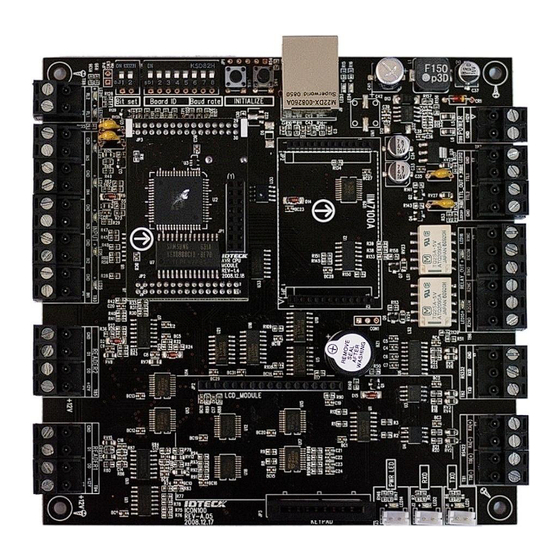
Select the data format (26bit/34bit) input to reader port. There is a switch for bit setting on the upper left side of iCON100 board. The switch is set to ‘OFF’ position as the default (26Bit Wiegand setting). If the switch is set to ‘ON’... - Page 8 Board ID is the unique address to communicate with PC. There is 5 channel DIP switch on the upper left side of the iCON100 board for board ID setting. Each DIP switch has assigned address value and the board ID is calculated by the sum value of each switch set to “ON”...
- Page 9 Baud rate is the speed rate during communication with host PC. The 3 DIP switches are assigned for baud rate setting on the upper left side of the iCON100 board. You can select one of 4800bps, 9600bps, 19200bps, 38400bps, 57600bps and 115200bps.You have to set applicable baud rate according to communication environment, and the connected devices on one loop must have the same baud rate.
-
Page 10: Wiring
Quick Installation Guide 7. Wiring 7.1 Power Connect (+) wire of DC 12V power to +12V terminal Connect GND (-) wire of DC 12V power to GND terminal 7.2 Input Connections Exit Button Connection (Input #1) - Connect one wire from an Exit Button to Input #1 - Connect the other wire from the Exit Button to the GND ... - Page 11 Quick Installation Guide 7.3 Output Connections Door Lock (Power Fail Safe) Connection (Relay #1) - Connect COM port of Relay #1 to DC+12V - Connect NC port of Relay #1 to (+) wire of door lock device - Connect GND port to (-) wire of door lock devices ...
- Page 12 - Connect Data-1 wire of the Proximity Reader to D1 of Reader Port Compatible Readers: - iCON100: Standard 26bit Wiegand Format Proximity Readers, Standard 26bit Wiegand + 8bit Burst Format Proximity and Keypad Readers. - iCON100SR: Standard 34bit Wiegand Format Proximity Readers, Standard 34bit Wiegand + 8bit Burst Format Proximity and Keypad Readers.
-
Page 13: Communication
8. COMMUNICATION 8.1 RS232 Communication Port Connection A 9-pin connector (Serial communication connector, female) is required to connect the iCON100 to a host computer via RS232 communication. Please follow the instructions. - Connect RS232-TX port of iCON100 to the pin #2(RX) of the 9-pin connector. - Page 14 8.2 RS-422 Communication Port Connection 8.2.1 RS-422 Connection (Single iCON100 Connection) An RS422/RS232 converter is required to use RS422 communication between the iCON100 and the PC. CAUTION: The INC400 converter is recommended for stable communication when the distance between the converter and the device is too far.
- Page 15 Quick Installation Guide 8.2.2 RS-422 Connection (Multiple iCON100 Connections) RS422/RS232 converter is required to use RS422 communication between multiple iCON100 and a host computer. Please follow the following instructions. First, you have to connect all RS422 port of all iCON100 in parallel.
- Page 16 8.3 TCP/IP Communication Port Connection (Optional) 8.3.1 How to Connect TCP/IP Module to iCON100 1) As below figure, Insert TCP/IP module to iCON100 in right direction. Direction of TCP/IP module have to be matched between iCON100 ( JP1 ) and TCP/IP ( JP1 ) module.
- Page 17 Quick Installation Guide 8.3.2 How to wire TCP/IP Communication Optional TCP/IP module is required for TCP/IP communication between the iCON100 and the PC. Please follow the instructions below; 1. Connect the LAN cable of the network system to the RJ45 jack of the iCON100.
- Page 18 Internal TCP/IP module is equipped on a iCON100/iCON100-SR then it communicates TCP/IP with Host PC. The iCON100/iCON100-SR communicates RS422 with another iCON100/iCON100-SR. First, you have to connect iCON100 RS422 port to RS422 port of iCON100(No.1 , TCP/IP communication) as below. - Connect iCON100(No.1) controller’s RS422-TX(-) to iCON100 controller’s RS422-RX(-) - Connect iCON100(No.1) controller’s RS422-TX(+) to iCON100 controller’s RS422-RX(+)
-
Page 19: Product Manual Download Information
For registered users of our homepage 1. Visit IDTECK’s homepage (www.idteck.com). 2. Click the Sign in button at the top of the homepage and log in using your registered ID and P/W. - Page 20 The specifications contained in this manual are subject to change without notice at any time. 5F, Ace Techno Tower B/D, 468, Gangseo-Ro, Gangseo-Gu, Seoul, 07573, Korea Tel : +82-2-2659-0055 Fax : +82-2-2659-0086 E-mail : webmaster@idteck.com FFQG0190 November. 2016 Copyright © 2016 IDTECK Co., Ltd.
Need help?
Do you have a question about the iCON100 and is the answer not in the manual?
Questions and answers