Table of Contents
Advertisement
Quick Links
Advertisement
Table of Contents

Related Manuals for IDTECK iTDC


Summary of Contents for IDTECK iTDC
- Page 1 IDTECK TROUBLE SHOOTING 2014 IDTECK. © All rights reserved 2011 Jan IDTECK. © All rights reserved...
-
Page 2: Table Of Contents
How can I have a backup database automatically with arranged schedule? l I have used the software for long time. The software has slowed down and “Database Insert Error” message appears. 3. Technical Training (Communication & System Integration) 2011 Jan IDTECK. © All rights reserved... -
Page 3: Installation
1. Installation (iTDC / iTDC PRO) 1) How to set up in/output configuration according to number of doors. 2) Error occurs when installing SQL Database. 3) All the software have been installed, but error message appears and can’t log-in to the software. - Page 4 Output for Reader #2 Input Ports #1 Exit Button for Door 1 Output Ports #4 Output to Output Port #1 Alarm for Door 2 Input Port #4, Output for Reader #2 2011 Jan IDTECK. © All rights reserved...
- Page 5 Output Ports #2 (MAIN) Input Ports #1 (MAIN) Alarm for Door 1 Exit Button for Door 1 Input Port #2, Output for Reader #1 & 2 Output to Output Port #1 2011 Jan IDTECK. © All rights reserved...
- Page 6 Output Ports #4 (EIO88) Input Ports #4 (EIO88) Alarm for Door 3 Door Contact for Door 3 Input Port #4, Output to Output Port #4 (EIO88) Output for Reader #4 2011 Jan IDTECK. © All rights reserved...
- Page 7 Output to Output Port #2 Output Ports #4 Input Ports #1 Alarm for Door 2 Exit Button for Door 1 Output to Output Port #1 Input Port #4, Output for Reader #2 2011 Jan IDTECK. © All rights reserved...
- Page 8 Input Ports #4 (EIO88) Output Ports #4 (EIO88) Door Contact for Door 4 Alarm for Door 4 Output to Output Port #4 (EIO88) Input Port #4(EIO88), Output for Reader #4 2011 Jan IDTECK. © All rights reserved...
- Page 9 ※ Following products must be installed to the computer prior to installing SQL Server 2005 Express Edition ㆍMicrosoft .NET Framework 2.0 ㆍMS-XML6 ㆍCheck ” I accept the licensing terms ㆍClick Install ㆍInitial Installation Complete, and conditions”, Click Next Click Next 2011 Jan IDTECK. © All rights reserved...
- Page 10 Click Next ㆍSelect “Entire feature will be installed ㆍ Click Next ㆍSelect ”Default Instance”, on local hard drive” for Database Service Click Next and Client Components, Click Next 2011 Jan IDTECK. © All rights reserved...
- Page 11 ㆍCheck ”SQL Server 및 SQL Browser”, Click Next the language in use, Click Next ㆍSelect ”Enable User Interface”, ㆍClick Next ㆍClick Install Click Next 2011 Jan IDTECK. © All rights reserved...
- Page 12 2) Error occurs when installing SQL Database. ㆍConfirm the Installation of all the ㆍClick Next when Installation is ㆍClick Finish products Completed ㆍRestart the computer when the Installation is completed 2011 Jan IDTECK. © All rights reserved...
- Page 13 Solution ① After Installing the software, Did you Configure Database Server Definition? : After installing the Database Server and iTDC PRO II S/W, you must configure Database Server Definition as Below to Log-In to the software properly. ㆍError Message 2 ㆍError Message 1...
- Page 14 3) All the software have been installed, but error message appears and can’t log-in to the software ㆍS/W screen for successful connection ㆍS/W screen for failed connection ㆍSave the setting and restart the S/W ㆍID: admin / PW: *leave it blank* 2011 Jan IDTECK. © All rights reserved...
-
Page 15: Management
2. Management (iTDC / iTDC PRO) 1) Door does not open. 2) Communication does not work. 3) Response speed of Event has slowed. 4) I would like to print T&A report, but I can’t find the report. 5) I don’t know how to do a database backup. - Page 16 A4. Yes, events appear on the s/w. (Same as Answer ① & ② for Question A2) A5. No, events do not appear on the s/w. (Same as Answer ③ & ④ for Question A2) 2011 Jan IDTECK. © All rights reserved...
- Page 17 [Set up] >> [Set System Data] >> Use [Card Holders] to register ID information [Access Control] >> Use [Card Holder Management] to register ID information [Access Control] >> [Card Holder Management] [Set up] >> [Set System Data] >> [Card Holders] 2011 Jan IDTECK. © All rights reserved...
- Page 18 : Door will open properly when the registered IDs are configured to designated access group. [Access Control] >> [Card Holder Management] >> [Access Group] [Access Control] >> [Card Holder Management] >> [Access Group] 2011 Jan IDTECK. © All rights reserved...
- Page 19 The maximum distance of Wiegand cable between controller and reader is 150m, but it is within 30~40m recommended to install the products for stable system operation. ※ Refer to the product manual for recommended cable and distance. Install within 30~40m 2011 Jan IDTECK. © All rights reserved...
- Page 20 Use same power source for reader and controller Connect ground wire when using separate power sources for reader and controller FGR006 In case using same power source for reader and controller 2011 Jan IDTECK. © All rights reserved...
- Page 21 1) Door does not open ★ Connecting Ground for Reader & Controller ID40WA +12V ID40WA +12V Ground In case using separate power source for reader and controller 2011 Jan IDTECK. © All rights reserved...
- Page 22 ★ When registering fingerprint using FGR006 or Hamster, the condition of the fingerprint can be checked on the software. If the condition of the fingerprint is 3 or lower, it is recommended to use Verification (1:1) Mode. 2011 Jan IDTECK. © All rights reserved...
- Page 23 : If the fingerprint is not identified properly, it may cause Fingerprint Error and the door will not open. Refer to below information for proper way of registering and identifying fingerprint. CORRECT INCORRECT ★ Bad fingerprint condition may cause timeout during fingerprint registration and may cause Fingerprint Error during identification. 2011 Jan IDTECK. © All rights reserved...
- Page 24 2) Communication does not work. I’m using Serial Communication. Solution ① Check if the Communication Cables are Connected Correctly. ※ Connecting INC400 Type A (RS422 to RS232) to iTDC INC400 ITDC 2011 Jan IDTECK. © All rights reserved...
- Page 25 Go to HARDWARE TAB and click DEVICE Com Port MANAGER Out of the Port List, Select the Port Number Baud Rate (i.e. COM1) for USB Serial Cable [System] >> [Loop Definition] 2011 Jan IDTECK. © All rights reserved...
- Page 26 2) Communication does not work. Board ID must be configured in same address as iTDC board. * In case of the controller (iTDC), use addresses from 000~127. * In case of using fingerprint reader (FINGER006, FGR006), use addresses from 128 and above.
- Page 27 : START RUN ping +IP Address 【When Operating Properly】 【When Network is not Connected Properly】 ★ In case the network connection is not stable, it is recommended to use CAT6 cable or higher. 2011 Jan IDTECK. © All rights reserved...
- Page 28 ② Check if the Communication Default Setting is Configured Correctly. : IP Address Setting, Port Setting ※ IP Address Insert the IP Address configured in TCP/IP Converter ※ TCP/IP Port No. Port Setting (Default: 5000) 2011 Jan IDTECK. © All rights reserved...
- Page 29 START PROGRAM IPSearch CLICK IPSearch.exe Type : STATIC IP ㆍSTATIC IP: Can only use STATIC IP for iTDC PRO S/W ㆍ Consult with network specialist for configuring IP Address, Gateway, Subnet Mask ㆍ IP Address : Can’t use same IP address within same network ㆍClick the Refresh button to search all LAN Converter...
- Page 30 START PROGRAM Wiznet CLICK 7100A_C.exe Serial Tab ㆍSpeed: 9600 ㆍFlow: CTS/RTS Network Mode ㆍ Can only use STATIC IP for iTDC PRO S/W ㆍDataBit: 8 is important : Server Mode ㆍ Consult with network specialist for configuring ㆍ...
- Page 31 ① Check the Number of Controllers Connected to One Loop : iTDC PRO II Software and iTDC controller uses polling method to communicate. Therefore, if the number of controller connected in one roof exceeds the recommended number, it may cause the communication to slow down.
- Page 32 Monthly Closing Time & Attendance >> Daily Time & Attendance Data management Annual Closing Time & Attendance >> Monthly Time & Attendance Data management Time & Attendance >> Annual Time & Attendance Data management 2011 Jan IDTECK. © All rights reserved...
- Page 33 Step 1) Run Microsoft SQL 2005 Management Studio and Explorer as the picture below. log in with ID and Password as below. Click right button of the mouse >> Tasks >>Click Back up Database… 2011 Jan IDTECK. © All rights reserved...
- Page 34 5) I don’t know how to do a database backup . Step 3) Click [Add] button Step 5) Select location where you would like to store the backed up database and type file name. Step4) Click […] button Step6) Click [OK] button 2011 Jan IDTECK. © All rights reserved...
-
Page 35: I Don't Know How To Do A Database Backup
5) I don’t know how to do a database backup . Step 7) Click [OK] button Step8) Click [OK] button 2011 Jan IDTECK. © All rights reserved... -
Page 36: Can I Recover A Database Backup File? L
Select database on Object Explorer as the picture below. Step 1) Run Microsoft SQL 2005 Management Studio Click right button of the mouse and log in with ID and Password. >> Select Restore Database… 2011 Jan IDTECK. © All rights reserved... - Page 37 6) Can I recover a database backup file? Step 3) Type name of database you would like to restore. Step4) Click [Add] button Select from device and Click [….] button. 2011 Jan IDTECK. © All rights reserved...
- Page 38 Step 7) Click [Options] on the left & upper corner, select and click [OK] button. the [Overwrite the existing database (WITH REPLACE)] and click [OK] button. Step6) Click [OK] button Step8) Click [OK] button 2011 Jan IDTECK. © All rights reserved...
-
Page 39: How Can I Have A Backup Database Automatically With Arranged Schedule? L
SQL Server Agent is needed for automatic maintenance function when using Microsoft SQL Server 2005 Step 1) Run Microsoft SQL 2005 Management Studio Step 1) On Object Explorer, Select Management and log in with ID and Password. click right button >> Maintenance Plans Wizard. 2011 Jan IDTECK. © All rights reserved... - Page 40 7) How can I have a backup database automatically with arranged schedule? Step 3) Click [Next] button Step 5) Set Maintenance plans according to automatic maintenance plan. Step4) After typing the name, click [change…]button Step6) Click [Next] button for Schedule. 2011 Jan IDTECK. © All rights reserved...
- Page 41 Select what you will automatically manage. Step8) Place “Shrink Database” on the top and *Shrink Database and Back up Database is usually “Back Up Database” as second. checked for automatic management. Click [Next] button. 2011 Jan IDTECK. © All rights reserved...
- Page 42 7) How can I have a backup database automatically with arranged schedule? Step 9) Choose “Select one or more” in Database Step 11) Click [Next] button Step10) Select database you will manage and Step12) Choose “Select one or more” for database. click [OK] button. 2011 Jan IDTECK. © All rights reserved...
- Page 43 7) How can I have a backup database automatically with arranged schedule? Step 13) Select database you will manage and Step14) Click [….] button in Folder category. click [OK] button. 2011 Jan IDTECK. © All rights reserved...
- Page 44 7) How can I have a backup database automatically with arranged schedule? Step16) Click [Next] button. Step 15) Select folder you will stored backed up database and click [OK] button. 2011 Jan IDTECK. © All rights reserved...
- Page 45 7) How can I have a backup database automatically with arranged schedule? Step 17) Click [Next] button Step18) Click [Finish] button. Step19) Click [Close] button. 2011 Jan IDTECK. © All rights reserved...
- Page 46 ※ Delete Card event and Card Alarm event. Step 2) Click [New Query] button. Step 1) Run Microsoft SQL 2005 Management Studio and log in with ID and password.. 2011 Jan IDTECK. © All rights reserved...
- Page 47 If you use Dual Pro II software you need to type ‘use DUAL_PRO_II_ACS’ instead of ‘use ITDC_PRO_II_ACS’ Step 6) Click [Execute] button. If you use Dual Pro II software you need to type ‘use DUAL_PRO_II_ACS’ instead of ‘use ITDC_PRO_II_ACS’ 2011 Jan IDTECK. © All rights reserved...
- Page 48 ‘ ITDC_PRO_II_ACS’ In the case you type the query as below, LOG file DB restore is not possible Step 2) Click [Execute] button. Step 3) Compress the DB as explained above 2011 Jan IDTECK. © All rights reserved...
-
Page 49: Technical Training (Communication & System Integration)
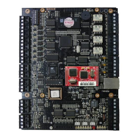
8) EXIT Button & Door Sensor Wiring 9) Door Lock Wiring 10) Board ID Setting for iTDC 11) Board ID Setting for FGR006 12) Communication Wiring 13) How to Install iTDC PRO S/W 2011 Jan IDTECK. © All rights reserved... - Page 50 4. Technical Training _Communication & System Integration (iTDC+FGR006+iTDC PRO II) 1) Controller Overview ① iTDC Main Board (Version 9.2.Z) Initialization Switch Board ID Switch Relay Output Port #1~4 Input Ports #1~7 TTL Output Port #1~3 TCP/IP Module Connector Reader Ports #1~4...
- Page 51 4. Technical Training _Communication & System Integration (iTDC+FGR006+iTDC PRO II) 1) Controller Overview Event Memory GAL IC Program Memory (Replaceable) 2011 Jan IDTECK. © All rights reserved...
- Page 52 1) Controller Overview ※ Product Version Check (Product Version / Firmware Version) ㆍiTDC version management is required as Program Memory is upgraded and replaced whenever the firmware is edited. ※ RMA Registration & Warranty Policy (http://www.idteck.com/support/online_rma.asp) ㆍiTDC Board Replacement / ROM (Program Memory) Replacement (Socket Type)
- Page 53 4. Technical Training _Communication & System Integration (iTDC+FGR006+iTDC PRO II) 1) Controller Overview ② EIO88 Expansion Board (Version 9.0.0) Relay Output Port #1~4 Relay Output Port #5~8 Input Port #1~4 Input Port #5~8 2011 Jan IDTECK. © All rights reserved...
- Page 54 4. Technical Training _Communication & System Integration (iTDC+FGR006+iTDC PRO II) 2) IN/OUTPUT Configuration ① IN/OUTPUT Configuration for 1~2 Door Control ※ iTDC Main Board : Door 1,2 Output Ports #1 iTDC Main Board Door Lock for Door 1 Input Ports #4 ...
- Page 55 4. Technical Training _Communication & System Integration (iTDC+FGR006+iTDC PRO II) 2) IN/OUTPUT Configuration ② IN/OUTPUT Configuration for 3 Door Control (Basic Configuration) ※ iTDC Main Board : Door 1 ※ EIO88 Board : Door 2 & 3 (Refer to Next Page)
- Page 56 4. Technical Training _Communication & System Integration (iTDC+FGR006+iTDC PRO II) 2) IN/OUTPUT Configuration ※ iTDC Main Board : Door 1 ※ EIO88 Board : Door 2 & 3 Input Ports #1 (EIO88) EIO88 Expansion Board Exit Button for Door 2 ...
- Page 57 _Communication & System Integration (iTDC+FGR006+iTDC PRO II) 2) IN/OUTPUT Configuration ③ IN/OUTPUT Configuration for 4 Door Control (Basic Configuration) ※ iTDC Main Board : Door 1 & 2 ※ EIO88 Board : Door 3 & 4 (Refer to Next Page)
- Page 58 4. Technical Training _Communication & System Integration (iTDC+FGR006+iTDC PRO II) 2) IN/OUTPUT Configuration ※ iTDC Main Board : Door 1 & 2 ※ EIO88 Board : Door 3 & 4 Input Ports #1 (EIO88) EIO88 Expansion Board Exit Button for Door 3 ...
- Page 59 4. Technical Training _Communication & System Integration (iTDC+FGR006+iTDC PRO II) 2) IN/OUTPUT Configuration ④ Software Configuration ㆍThe basic configuration for Input /Output can be done in the management software. 2011 Jan IDTECK. © All rights reserved...
- Page 60 4. Technical Training _Communication & System Integration (iTDC+FGR006+iTDC PRO II) 3) System Configuration ① System Configuration 2011 Jan IDTECK. © All rights reserved...
- Page 61 4. Technical Training _Communication & System Integration (iTDC+FGR006+iTDC PRO II) 3) System Configuration ② Serial Communication RS 422/485 Communication Converter HOST DOOR A iTDC DOOR B DOOR B DOOR A ID40WA +12V +12V D40WA 2011 Jan IDTECK. © All rights reserved...
- Page 62 4. Technical Training _Communication & System Integration (iTDC+FGR006+iTDC PRO II) 3) System Configuration ③ TCP/IP Communication TCP/IP Communication HOST iTDC DOOR A DOOR B DOOR B DOOR A ID40WA +12V +12V D40WA 2011 Jan IDTECK. © All rights reserved...
- Page 63 4. Technical Training _Communication & System Integration (iTDC+FGR006+iTDC PRO II) 4) Communication Cable ① Transmission Media Transmission media Guided Unguided (wired) (wireless) Twisted-pair Coaxial Fiber-optic cable cable cable 2011 Jan IDTECK. © All rights reserved...
- Page 64 4. Technical Training _Communication & System Integration (iTDC+FGR006+iTDC PRO II) 4) Communication Cable ② Twisted Pair Cable • UTP : Unshielded Twisted Paired Copper Cable • FTP : (Overall) Foiled Twisted Paired Copper Cable • STP : (Overall) Shielded (and Individually Shielded Pair) Twisted Paired Copper Cable ※...
- Page 65 4. Technical Training _Communication & System Integration (iTDC+FGR006+iTDC PRO II) 4) Communication Cable ③ Recommendation Cable a. Data Cable : Applied for Card Reader (Wiegand), Controller (RS232, RS422, RS485, TCP/IP) ㆍSTP : 24&22 AWG Twisted 2 Pair ㆍFTP : 22 AWG Twisted 2 Pair ㆍUPT : Category 5, Category 6...
- Page 66 4. Technical Training _Communication & System Integration (iTDC+FGR006+iTDC PRO II) 4) Communication Cable ④ Cable Distance Maximum Description Recommendation Cable Distance iTDC/iTDC-SR Power (DC12V) Belden #9409, 18 AWG ① DC Power <--> iTDC 2 conductor, unshielded Belden #9512, 22 AWG...
- Page 67 4. Technical Training _Communication & System Integration (iTDC+FGR006+iTDC PRO II) 4) Communication Cable ⑤ Cable Grounding • Definition ① To make an electric connection between electric devices and the ground • Purpose ① To avoid lightening and static electricity ②To prevent Over flow of electricity or Over Voltage – Stable system operation •...
- Page 68 4. Technical Training _Communication & System Integration (iTDC+FGR006+iTDC PRO II) 4) Communication Cable STP Cable Composition HOST PC Sheath Communication Wire Shield Connect Shield Wire to GND of Controller Connect only one end of the Shield to Ground TCP/IP Module (IIM7100A) 2011 Jan IDTECK.
- Page 69 4. Technical Training _Communication & System Integration (iTDC+FGR006+iTDC PRO II) 5) Controller Power Wiring ① Power Board (ID40WA) ① DC Power Output Terminal ㆍ1: DC +12V ㆍ2: GND ⑤ Backup Battery Connection Cable ② Power LED ㆍRed : + Connector ㆍBlack : -...
- Page 70 4. Technical Training _Communication & System Integration (iTDC+FGR006+iTDC PRO II) 5) Controller Power Wiring ② Controller Power Wiring ※ Supply 2-3 times higher current than the whole system’s current consumption. +12V AC POWER INPUT iTDC 90 ~ 240V AC ID40WA...
- Page 71 4. Technical Training _Communication & System Integration (iTDC+FGR006+iTDC PRO II) 5) Controller Power Wiring ③ Wiring for Warning Alarm ※ To activate the warning alarm, connect the signal to the input terminal of the controller to notify the AC power cut off or low battery.
- Page 72 4. Technical Training _Communication & System Integration (iTDC+FGR006+iTDC PRO II) 6) Initialization ① Initialization Using the Hardware ※ Initialization of All Data from iTDC PRESS Initialization begins when the buttons are pushed down for two seconds Initialize END System Restart…...
- Page 73 6) Initialization ② Initialization Using the Software ※ Initialization of All Data from iTDC or Initialization of Only Certain Data from iTDC : System Initialization, Card Data Initialization, Event Data Initialization, Time Schedule Initialization 2011 Jan IDTECK. © All rights reserved...
- Page 74 4. Technical Training _Communication & System Integration (iTDC+FGR006+iTDC PRO II) 7) FGR006 Reader Wiring ※ ID Registration in the Controller and ID+Fingerprint Registration Must Be Done Respectively to Properly Identify the User. FGR006 2011 Jan IDTECK. © All rights reserved...
- Page 75 4. Technical Training _Communication & System Integration (iTDC+FGR006+iTDC PRO II) 8) Exit Button & Door Sensor Wiring iTDC / iTDC-SR Main Board 2011 Jan IDTECK. © All rights reserved...
- Page 76 4. Technical Training _Communication & System Integration (iTDC+FGR006+iTDC PRO II) 9) Door Lock Wiring ① Fail Secure Lock ※ Reverse Diode Connection Reverse Diode is connected to prevent electrical noise during the use. Electrical noise may cause system malfunctions such as communication failure, system configuration change, etc. and also may decrease the lifetime of the device.
- Page 77 4. Technical Training _Communication & System Integration (iTDC+FGR006+iTDC PRO II) 9) Door Lock Wiring ② Fail Safe Lock ※ Reverse Diode Connection Reverse Diode is connected to prevent electrical noise during the use. Electrical noise may cause system malfunctions such as communication failure, system configuration change, etc. and also may decrease the lifetime of the device.
- Page 78 4. Technical Training _Communication & System Integration (iTDC+FGR006+iTDC PRO II) 10) Board ID Setting for iTDC ※ Board ID Configuration Board ID is a distinctive address assigned to each unit. Overlapping board IDs within a single communication loop will cause communication error.
- Page 79 4. Technical Training _Communication & System Integration (iTDC+FGR006+iTDC PRO II) 10) Board ID Setting for iTDC ADDRESS VALUE Board ID : 1+2+16 = 19 2011 Jan IDTECK. © All rights reserved...
- Page 80 4. Technical Training _Communication & System Integration (iTDC+FGR006+iTDC PRO II) 11) Board ID Setting for FGR006 ※ The Board ID of the Fingerprint Readers (FGR006, FINGER006) Must Be Configured from 128 (or above). ADDRESS VALUE 2011 Jan IDTECK. © All rights reserved...
- Page 81 4. Technical Training _Communication & System Integration (iTDC+FGR006+iTDC PRO II) 12) Communication Wiring ① Serial Communication Diagram (iTDC & FGR006 in One Loop) HOST PC CONVERTER Max. 1200m TX- (Yellow) TX+ (Gray) RX+ (Brown) RX- (Blue) iTDC iTDC FGR006 FGR006...
- Page 82 4. Technical Training _Communication & System Integration (iTDC+FGR006+iTDC PRO II) 12) Communication Wiring ② Bypass Communication Diagram (iTDC & FGR006 in One Loop) Connect FGR006 #3(or iTDC #3) & FGR006 #n(or iTDC #n) Direct Connection iTDC RX+ <-> RX+ Board ID: 001 RX- <->...
- Page 83 4. Technical Training _Communication & System Integration (iTDC+FGR006+iTDC PRO II) 13) How to Install iTDC PRO S/W ① SQL Server 2005 Express Edition Installation ※ Following products must be installed to the computer prior to installing SQL Server 2005 Express Edition ㆍMicrosoft .NET Framework 2.0...
- Page 84 4. Technical Training _Communication & System Integration (iTDC+FGR006+iTDC PRO II) 13) How to Install iTDC PRO S/W ㆍBegin Installation of SQL Server, ㆍConfirm the SQL Server System ㆍInsert ”Name / Company “ Click Next Configuration Check, Click Next ...
- Page 85 4. Technical Training _Communication & System Integration (iTDC+FGR006+iTDC PRO II) 13) How to Install iTDC PRO S/W ㆍSelect ”Use the built-in System account” ㆍSelect ”Mixed Mode”, Insert Password, ㆍFor Collation, use the default setting ㆍSelect ”Local System” Click Next ...
- Page 86 4. Technical Training _Communication & System Integration (iTDC+FGR006+iTDC PRO II) 13) How to Install iTDC PRO S/W ㆍConfirm the Installation of all the ㆍClick Next when Installation is ㆍClick Finish products Completed ㆍRestart the computer when the Installation is completed 2011 Jan IDTECK.
- Page 87 4. Technical Training _Communication & System Integration (iTDC+FGR006+iTDC PRO II) 13) How to Install iTDC PRO S/W ② SQL Server 2005 Surface Area Configuration ※ START Microsoft SQL Server 2005 Configuration Tools “SQL Server Surface Area Configuration”...
- Page 88 4. Technical Training _Communication & System Integration (iTDC+FGR006+iTDC PRO II) 13) How to Install iTDC PRO S/W ③ iTDC PRO II Software Installation ㆍInitial Installation Screen ㆍClick Next ㆍInstallation in Progress 2011 Jan IDTECK. © All rights reserved...
- Page 89 4. Technical Training _Communication & System Integration (iTDC+FGR006+iTDC PRO II) 13) How to Install iTDC PRO S/W ㆍDatabase Connection Configuration ㆍStarts generating a new database ㆍClick “Finish” to end the installation ㆍSERVER: Insert the IP address of where SQL Server is installed...
- Page 90 ④ DATABASE Server Definition ㆍInsert Server Name / IP Address ㆍClick “Connection Test” to check the ㆍS/W screen for successful connection : If the iTDC PRO II and Database are connection status installed on the same location, insert “localhost” ㆍInsert Server User ID : Insert SQL Server User ID (“sa”)
- Page 91 4. Technical Training _Communication & System Integration (iTDC+FGR006+iTDC PRO II) 13) How to Install iTDC PRO S/W a. Loop Definition 2011 Jan IDTECK. © All rights reserved...
- Page 92 4. Technical Training _Communication & System Integration (iTDC+FGR006+iTDC PRO II) 13) How to Install iTDC PRO S/W b. Controller Definition 2011 Jan IDTECK. © All rights reserved...
- Page 93 4. Technical Training _Communication & System Integration (iTDC+FGR006+iTDC PRO II) 13) How to Install iTDC PRO S/W c. Biometrics Reader Definition 2011 Jan IDTECK. © All rights reserved...
- Page 94 4. Technical Training _Communication & System Integration (iTDC+FGR006+iTDC PRO II) 13) How to Install iTDC PRO S/W d. Door/Reader Definition 2011 Jan IDTECK. © All rights reserved...
Need help?
Do you have a question about the iTDC and is the answer not in the manual?
Questions and answers