IDTECK 100R Quick Installation Manual
Hide thumbs
Also See for 100R:
- User manual (40 pages) ,
- Quick installation manual (16 pages) ,
- Manual (71 pages)
Table of Contents
Advertisement
Advertisement
Table of Contents

Related Manuals for IDTECK 100R


Summary of Contents for IDTECK 100R
- Page 1 Quick Installation Guide 100R IP100R...
-
Page 2: Table Of Contents
Quick Installation Guide Table of Contents 1. SAFETY INFORMATION ..................... 3 2. IDENTIFYING SUPPLIED PARTS ................... 6 3. WALL MOUNT INSTALLATION ..................7 4. WIRE COLOR TABLE ....................9 5. WIEGAND OUTPUT FUNCTION .................. 10 6. RECOMMENDED CABLE TYPE AND PERMISSIBLE LENGTH ..........11 7. -
Page 3: Safety Information
9. If this product fails to operate normally, contact the nearest service center. Never disassemble or modify this product in any way. (IDTECK is not liable for problems caused by unauthorized modifications or attempted repair.) 10. - Page 4 Quick Installation Guide CAUTION 1. Do not drop objects on the product or apply strong blows to it. Keep away from a location subject to excessive vibration or magnetic interference. 2. Do not install in a location subject to high temperature (over 50°C), low temperature (below -30°C), or high humidity.
- Page 5 Quick Installation Guide Important Safety Instructions 1. Read these instructions. 2. Keep these instructions. 3. Heed all warnings. 4. Follow all instructions. 5. Do not use this apparatus near water. 6. Clean only with dry cloth. 7. Do not block any ventilation openings. Install in accordance with the manufacturer’s instructions.
-
Page 6: Identifying Supplied Parts
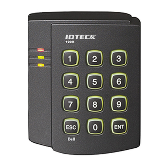
Quick Installation Guide 2. IDENTIFYING SUPPLIED PARTS Check all components in the gift box when purchasing. Contact the vendor where you purchased the product if any components are missing. Master Card (1ea) Main Unit (1ea) Wall Mount (1ea) Quick Guide (1copy) 6.0x30mm 3.5x12mm Screw (4ea) 3.5x40mm Screw (4ea) -
Page 7: Wall Mount Installation
Quick Installation Guide 3. WALL MOUNT INSTALLATION Use the provided template to drill two 6-32 holes and one 1/2" hole on the proper location of the wall to mount the Wall Mount bracket as shown below. 2. Install wall mount to the wall using 2 screws. Insert 5 O-rings to the wall mount as indicated, then route the cable of the main unit through the center hole and push the main unit to wall mount to lock the main unit and make sure that the main unit is locked with wall mount. - Page 8 Quick Installation Guide ※ CAUTION Before mounting the 100R unit to the Wall Mount bracket, operational testing of the unit should be completed, as the locking pins will lock the unit to the Wall Mount. Removing the unit from the Wall Mount bracket after they have been installed together may cause damages to the bracket and render its effectiveness.
-
Page 9: Wire Color Table
Quick Installation Guide 4. WIRE COLOR TABLE I/O PORT NAME SIGNAL NAME COLOR CODE 2-PIN Main Power (+12V) DC +12V Power Ground Black 10-PIN Door Relay (NC) NC (1) Blue (White Stripe) Door Relay (COM) COM (1) Gray (Red Stripe) Door Relay (NO) NO (1) White (Red Stripe) -
Page 10: Wiegand Output Function
Quick Installation Guide 5. WIEGAND OUTPUT FUNCTION The default output format of 100R/IP100R is TTL and Chime Bell output. But, you can configure the 100R/IP100R to generate output in Wiegand format and use it like a reader. (The 100R/IP100R can output data from card reading, but can’t output data from keypad input.) If you want to generate Wiegand instead of TTL output format, follow the table below. -
Page 11: Recommended Cable Type And Permissible Length
Quick Installation Guide 6. RECOMMENDED CABLE TYPE AND PERMISSIBLE LENGTH Maximum Reference Description Cable Specification Distance 100R series Power (DC12V) Belden #9409,18 AWG DC Power-> 100R series 2 conductor, unshielded Belden #9512,22 AWG Reader(Power and Data) 4 conductor, shielded 150m... -
Page 12: System Wiring For Typical Application
Quick Installation Guide 8. SYSTEM WIRING FOR TYPICAL APPLICATION... - Page 13 Quick Installation Guide 8.1 Power Connection Connect (+) wire of DC +12V power to Red wire. ● Connect Power GND (-) wire of DC +12V to Black wire. ● 8.2 Door Lock Connection Connection of POWER FAIL SAFE: Door Lock Connect Door RELAY (COM), Grey with Red stripe wire to DC +12V ●...
- Page 14 Quick Installation Guide 8.4 Exit Button Connection Connect one of the wires of Exit Button to Exit Button Input, Orange wire. ● Connect the other wire of Exit Button to Power GND (-) wire. ● (If a normally closed Exit button is used, then see section 12-55 to change the detection scheme from the defaulted setting) 8.5 Door Contact Sensor Connection Connect Door Contact sensor (COM) wire to Door Contact Input, Yellow with Red stripe wire.
- Page 15 Quick Installation Guide 8.7 Auto-Dialer Connection (Separate purchase required) The Auto-dialer function of this unit has not been evaluated by UL. Connect the input wire of Auto-Dialer to TTL output, Orange with White stripe wire. ● Connect (+) wire of Auto-Dialer to DC +12V (be sure that the existing power supply has enough ●...
-
Page 16: System Initialization
Quick Installation Guide 9. SYSTEM INITIALIZATION ※ WARNING: It will initialize all the values of the products to factory default. 9.1 Initialization using the command 1) Present a Master RF card close to the product 2) Press the ‘ENT’ button after pushing the ‘9’... - Page 17 9.3 Wire Initialization Execute initialization when you have lost master card. 100R: v5.0.4 or later / IP100R: v2.0.2 or later 1. Power off the device. 2. Connect the Green cable to Orange cable(White stripe) and then power up the device again.
-
Page 18: Fcc Registration Information
Quick Installation Guide 10. FCC REGISTRATION INFORMATION FCC Requirements Part 15 CAUTION: Any changes or modifications in construction of this device which are not expressly approved by the responsible for compliance could void the user's authority to operate the equipment. NOTE: This device complies with Part 15 of the FCC rules. -
Page 19: Online Rma Policy & Free Service Criteria
Also, additional charge may occur for product replacement. • All RMA products will be tested by IDTECK’s service team. If no problems were found after conducting the test, additional service/repair fees will be charged. - Page 20 - If serious defect is found. - All RMA products will be tested by IDTECK’s service team. If no problems were found after conducting the test, additional service/repair fees (10 %) will be charged. 2. Base Date : Ship-out Date 3.
- Page 21 The specifications contained in this manual are subject to change without notice. 5F, Ace Techno Tower B/D, 468, Gangseo-ro Gangseo-Gu, Seoul, 07573, Korea Tel : +82-2-2659-0055 Fax : +82-2-2659-0086 E-mail : webmaster@idteck.com Website: www.idteck.com FFQG0189 April 25, 2018. Copyright IDTECK., Ltd.
Need help?
Do you have a question about the 100R and is the answer not in the manual?
Questions and answers