
Subscribe to Our Youtube Channel
Related Manuals for Hermle Z 326


Summary of Contents for Hermle Z 326
- Page 1 Service Instruction Universal Centrifuge Z 326 Page 1 of 48 SERVICE INSTRUCTION Z 326 © HERMLE Labortechnik GmbH Version 01/2010...
-
Page 2: Table Of Contents
7.3.2.1 Adjustment of the centrifuge type 7.3.2.2 Adjustment of the operation mode 7.3.2.3 Submenu Adjustment/Correction of the imbalance cut off value 7.3.2.4 Submenu Activating/Deactivating of the electronical Imbalance Page 2 of 48 SERVICE INSTRUCTION Z 326 © HERMLE Labortechnik GmbH Version 01/2010... - Page 3 10.1.1 Flow diagram 230 V / 120 V / 50-60 Hz; Page 2 11 SPARE PART LIST Technical modification rights reserved. © HERMLE Labortechnik GmbH 2010 / 01 Page 3 of 48 SERVICE INSTRUCTION Z 326 © HERMLE Labortechnik GmbH...
-
Page 4: Technical Data
6 TECHNICAL DATA 6.1 Acceleration times Z 326 (120 V / 230 V) in min/sec Rotor-Number 221.12 V03 1:35 0:48 0:33 0:25 0:21 0:18 0:16 0:15 0:15 0:15 220.72 V06 1:51 0:52 0:36 0:28 0:23 0:20 0:18 0:15 0:14 0:14 221.16 V03... -
Page 5: Imbalance Shut Off Data
6 TECHNICAL DATA 6.3 Imbalance shut off data Z 326 (120 V / 230 V) List of rotors which cannot be adjusted, but which are set by the work of using motion detectors. Rotor-Number Shut off speed Permitted imbalance Imbalance shut off... -
Page 6: Service Instructions
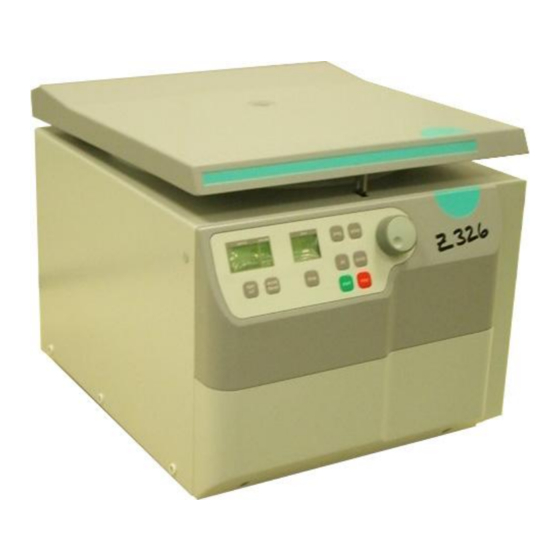
Model Z 326 is a micro processor controlled laboratory centrifuge. The actuation is a three phase asynchronous motor which is controlled by frequency converter. Model Z 326 has an independent error detection program, displaying possible errors and therefore supporting the trouble shooting process. -
Page 7: Control Board
LCD-Display Incremental Shaft Encoder shadrehgeber Keyborad Foil Upper Front Housing Page 7 of 48 SERVICE INSTRUCTION Z 326 © HERMLE Labortechnik GmbH Version 01/2010... -
Page 8: Frequency Converter
As soon as the lid gets closed the rotor number will be indicated in the speed display. (See photo in chapter 7.2.3) Aerial Below side of the rotor Transponder Page 8 of 48 SERVICE INSTRUCTION Z 326 © HERMLE Labortechnik GmbH Version 01/2010... -
Page 9: Over Speed Protection
A micro switch that controls for certain rotors the displacement of the motor and shut off if there it too much imbalance. The micro switch should be adjusted according to the instruction of the company. (See chapter 7.4.13. See also list 6.3) Page 9 of 48 SERVICE INSTRUCTION Z 326 © HERMLE Labortechnik GmbH Version 01/2010... -
Page 10: Operation Menu
7.3.1 to 7.3.2.3. Part 1 is accessible for the USER and different points can be read respectively settled. This is also described in the instruction manual. Part 2 is for internal use respectively for trained service personnel outdoors Hermle L ABOR ECHNIK only. -
Page 11: Activation Of The Operation Menu (Part 1)
2 seconds. The letter stands for the different versions of the units which are currently stored in the control board: cool heat no for nothing Now it follows a display test for about 5 seconds as shown here under. Page 11 of 48 SERVICE INSTRUCTION Z 326 © HERMLE Labortechnik GmbH Version 01/2010... -
Page 12: Submenu Motor Starts
• Activate the operation menu as described in chapter 7.3.1. • Turn the potentiometer until the special digit „service H“ appears in the display „acc/dec”. In the display „rpm/rcf“ the duty cycle is indicated now. Page 12 of 48 SERVICE INSTRUCTION Z 326 © HERMLE Labortechnik GmbH Version 01/2010... -
Page 13: Submenu Running Time Of The Motor
• Turn the potentiometer until the special digit „service S“ appears in the display „acc/dec”. In the display „rpm/rcf“ the actual software status is indicated now. Page 13 of 48 SERVICE INSTRUCTION Z 326 © HERMLE Labortechnik GmbH Version 01/2010... -
Page 14: Submenu Software Status Of The Frequency Converter
• Now the 99 last occurred error messages are indicated in the display „rpm/rcf“. Whereas the first two numbers do describe the place number and the last two numbers do describe the occurred error. Page 14 of 48 SERVICE INSTRUCTION Z 326 © HERMLE Labortechnik GmbH Version 01/2010... - Page 15 Over current converter Timeout between control unit and converter other error of the converter Speed error Overspeed Setup error Rotor is not allowed in this centrifuge Page 15 of 48 SERVICE INSTRUCTION Z 326 © HERMLE Labortechnik GmbH Version 01/2010...
-
Page 16: Submenu Setup Of The Temperature
• Turn the potentiometer until the special digit „service L“ appears in the display „acc/dec”. • By pressing the key rpm/rcf the display „rpm/rcf“ is now activated and you can setup the respective option with the potentiometer. Page 16 of 48 SERVICE INSTRUCTION Z 326 © HERMLE Labortechnik GmbH Version 01/2010... -
Page 17: Submenu Setup Of The Keypad Tone
The keypad tone has to be switched on again after the reactivation of the signal generator. However the audible error message is automatically activated if the signal generator has been reactivated. Page 17 of 48 SERVICE INSTRUCTION Z 326 © HERMLE Labortechnik GmbH Version 01/2010... -
Page 18: Submenu Setup Volume Of The Signal Generator
Otherwise the setups were all for nothing. If the storage has been successful in the display „rpm/rcf“ the value of the imbalance sensor and the word „StorE“ are indicated. Page 18 of 48 SERVICE INSTRUCTION Z 326 © HERMLE Labortechnik GmbH Version 01/2010... -
Page 19: Submenu Setup Of The Signal Melody
• Activate the operation menu as described in chapter 7.3.1. • Turn the potentiometer until the special digit „service F“ appears in the display „acc/dec”. Non-calibrated indication Page 19 of 48 SERVICE INSTRUCTION Z 326 © HERMLE Labortechnik GmbH Version 01/2010... -
Page 20: Submenu Indication Of The Imbalance Value Of The Rotor
• In the bottom line of the display „rpm/rcf“ the real imbalance value is indicated. In the top line the rotor number is indicated (in this case 221.17 V0?). Page 20 of 48 SERVICE INSTRUCTION Z 326 © HERMLE Labortechnik GmbH Version 01/2010... -
Page 21: Submenu Keyboard Test
• Turn the potentiometer until the special digit „service d“ appears in the display „acc/dec“. • Example: Revision number 0 Revision number 1 without automatical with automatical check check (in this case (off)) Page 21 of 48 SERVICE INSTRUCTION Z 326 © HERMLE Labortechnik GmbH Version 01/2010... -
Page 22: Activation Of The Service Menu (Part 2)
ATTENTION: Please do not adjust any other centrifuge types than the mentioned one on the type label of the unit. Otherwise there may occur defects, both in the electronic and the mechanic components. Page 22 of 48 SERVICE INSTRUCTION Z 326 © HERMLE Labortechnik GmbH Version 01/2010... -
Page 23: Adjustment Of The Operation Mode
• As we have already mentioned in the beginning this letters will appear when you switch on the unit during the normal operation (see chapter 7.3.1). Page 23 of 48 SERVICE INSTRUCTION Z 326 © HERMLE Labortechnik GmbH Version 01/2010... -
Page 24: Submenu Adjustment/Correction Of The Imbalance Cut Off Value
Otherwise the setups were all for nothing. If the storage has been successful in the display „rpm/rcf“ the value of the imbalance sensor and the word „StorE“ are indicated. Page 24 of 48 SERVICE INSTRUCTION Z 326 © HERMLE Labortechnik GmbH Version 01/2010... -
Page 25: Submenu Activating/Deactivating Of The Electronical Imbalance
Turn the device off and turn it on again. The word "UA" appears now in the display "time" (A-3),. Now you can adjust the mechanical imbalance detector, see chapter 7.4.13 "Adjustment of the mechanical imbalance detector". Page 25 of 48 SERVICE INSTRUCTION Z 326 © HERMLE Labortechnik GmbH Version 01/2010... -
Page 26: Mounting Support
• Loosen the 5 screws under the control panel and pull away the panel forward. • Remove the interface cable on the control board. (Connection between control board and control panel). remove loosen Loosen and pull away forward abziehen Page 26 of 48 SERVICE INSTRUCTION Z 326 © HERMLE Labortechnik GmbH Version 01/2010... -
Page 27: Replacing The Incremental Shaft Encoder
• Loosen all electrical contacts to the display on the back of the front housing. • Remove the 4 fastening screws of the display and pull away the display upwards. remove Page 27 of 48 SERVICE INSTRUCTION Z 326 © HERMLE Labortechnik GmbH Version 01/2010... -
Page 28: Replacing The Foil Keyboard
• Re-assemble the unit in reverse order. • Make sure the lid sealing, which is also the rotor chamber sealing, is placed correctly. You can use a small Allan key. Page 28 of 48 SERVICE INSTRUCTION Z 326 © HERMLE Labortechnik GmbH Version 01/2010... -
Page 29: Replacing The Lid Gasket
(see chapter 7.4.5.). Make sure that the cut-out of the chamber sealing to the airflow is not covered. Page 29 of 48 SERVICE INSTRUCTION Z 326 © HERMLE Labortechnik GmbH Version 01/2010... -
Page 30: Replacing The Hinges
• Make sure the lid rests on the lid gasket straight and continuous. Tighten the fasting screws firmly at the backside of the unit after the adjustment. Page 30 of 48 SERVICE INSTRUCTION Z 326 © HERMLE Labortechnik GmbH Version 01/2010... -
Page 31: Replacing The Aerial (Rotor Sensor)
• Remove the connection cable on the control board and remove the aerial. • Put in the new aerial. • Re-assemble the unit in reverse order. Page 31 of 48 SERVICE INSTRUCTION Z 326 © HERMLE Labortechnik GmbH Version 01/2010... -
Page 32: Replacing The Motor Resp. The Motor Bearings
• When tightening the motor mount screws, please pay attention the motor rubber mounts are not being twisted. • When connecting the motor with the electricity, take care of the rotating direction (Direction of arrow). • Re-assemble the unit in reverse order. Page 32 of 48 SERVICE INSTRUCTION Z 326 © HERMLE Labortechnik GmbH Version 01/2010... -
Page 33: Replacing The Power Board
• Remove the lower covering of the front housing as described in chapter 7.4.1. • Remove all cable connections to the power board. • Remove the four screws. remove • Re-assemble the unit in reverse order. Page 33 of 48 SERVICE INSTRUCTION Z 326 © HERMLE Labortechnik GmbH Version 01/2010... -
Page 34: Replacing The Frequency Converter
• Lay the motor down on its side and remove the two fixing screws of the green circuit board on the rear side (look up in chapter 7.2.8). • Replace the board and re-assemble the unit in reverse order. Page 34 of 48 SERVICE INSTRUCTION Z 326 © HERMLE Labortechnik GmbH Version 01/2010... - Page 35 To adjust the imbalance value, you have to bridge the movement sensor with an adapter at SV2 (speed/imbalance) on the control unit. You can demand this bridge at Hermle Labortechnik GmbH. • Put in a rotor into the unit and fasten the rotor nut.
-
Page 36: Replacing The Control Panel
• Remove the lower screws and the center screw of the mounting plate. Upon this there are fixed the electronically components. • Remove the electrical connections of the break resistance to the frequency converter. • Tilt the mounting plate forwards. remove Page 36 of 48 SERVICE INSTRUCTION Z 326 © HERMLE Labortechnik GmbH Version 01/2010... -
Page 37: Replacing The Signal Generator
• Remove the lower covering of the front housing as described in chapter 7.4.1. • Remove the electrical supply on the control board (1). • Remove the fixing screws and put in the new lid lock. Page 37 of 48 SERVICE INSTRUCTION Z 326 © HERMLE Labortechnik GmbH Version 01/2010... - Page 38 5.) Perhaps you have to bent the steel nibs of the other micro switches of the end stops into their position. 6.) Tighten all the screws well. Page 38 of 48 SERVICE INSTRUCTION Z 326 © HERMLE Labortechnik GmbH Version 01/2010...
-
Page 39: Trouble Shooting
• Now open the lid of the centrifuge. • Turn the hexagon nut back to its position. • Switch the centrifuge on again, for go on working. Page 39 of 48 SERVICE INSTRUCTION Z 326 © HERMLE Labortechnik GmbH Version 01/2010... -
Page 40: Description Of The Error Message System
Send in rotor for replacing the transponder Error No. 11: Temperature sensor is defective (for refrigerated units only) • Cause: Temperature sensor is defective • Solution: Temperature sensor hast o be replaced. Page 40 of 48 SERVICE INSTRUCTION Z 326 © HERMLE Labortechnik GmbH Version 01/2010... - Page 41 Seconds Z 216 MK Z 32 HK Z 366 Z36 HK Z 326 und Z 326 K Seta 2 • Cause: Shaft encoder defective or parting of a cable at shaft encoder, possibly loose magnet. • Solution: Make sure speed magnet has a firm fit, fix it with super glue.
- Page 42 Error No. 48: Timeout between control unit and frequency converter • Cause: Software of the control unit has a black out • Solution: Restart the unit; Control unit is defective Page 42 of 48 SERVICE INSTRUCTION Z 326 © HERMLE Labortechnik GmbH Version 01/2010...
- Page 43 Error No. 99: Rotor is not allowed in this centrifuge • Cause: Rotor is not allowed for this unit • Solution: Use rotor that is allowed in this unit Page 43 of 48 SERVICE INSTRUCTION Z 326 © HERMLE Labortechnik GmbH Version 01/2010...
-
Page 44: Maintenance
The maintenance procedure has to be repeated every 10 to 15 runs, but at least once a week! Page 44 of 48 SERVICE INSTRUCTION Z 326 © HERMLE Labortechnik GmbH Version 01/2010... -
Page 45: Glass Breakage
ATTENTION: Because the temperature may rise during the sterilization, rotors, boxes and bottles must not be closed respectively must be totally unscrewed. Chemical sterilization Bottles, boxes and rotors may be treated with the usual liquid disinfectants Page 45 of 48 SERVICE INSTRUCTION Z 326 © HERMLE Labortechnik GmbH Version 01/2010... -
Page 46: Circuit Diagrams
10 CIRCUIT DIAGRAMS 10.1 Flow diagrams 10.1.1 Flow diagram 230 V / 120 V / 50-60 Hz; Page 1 Page 46 of 48 SERVICE INSTRUCTION Z 326 © HERMLE Labortechnik GmbH Version 01/2010... - Page 47 10 CIRCUIT DIAGRAMS 10.1 Flow diagrams 10.1.1 Flow diagram 230 V / 120 V / 50-60 Hz; Page 2 Page 47 of 48 SERVICE INSTRUCTION Z 326 © HERMLE Labortechnik GmbH Version 01/2010...
-
Page 48: Spare Part List
950.174 950.174 Below front bonnet (Main switch in the bottom) 934.023 311.01.27 Type description 954.021 312.01.07 Below front bonnet (Main switch in the front) 934.024 311.01.27_A Page 48 of 48 SERVICE INSTRUCTION Z 326 © HERMLE Labortechnik GmbH Version 01/2010...
Need help?
Do you have a question about the Z 326 and is the answer not in the manual?
Questions and answers