
Related Manuals for Hermle Z 306


Summary of Contents for Hermle Z 306
- Page 1 Service Manual Universal Centrifuge Z 306 © Hermle Labortechnik GmbH Service Manual Z 306 V2.13/2013...
-
Page 2: Table Of Contents
8.1 Acceleration times Z 306 (120 V / 230 V) in min/sec ....................1 8.2 Decelertaion times Z 306 (120 V / 230 V) in min/ sec ..................... 2 8.3 Imbalance shut off data Z 306 (120V / 230 V ) ......................3 9. - Page 3 Flow diagram 230 V / 120 V / 50-60 Hz, page 1 ....................45 12.2 Flow diagram 230 V / 120 V / 50-60 Hz, page 2 ....................46 12.3 Control board ..............................47 Spare part list ........................ 48 © Hermle Labortechnik GmbH Service Manual Z 306...
-
Page 5: Technical Data
TECHNICAL DATA 8. Technical Data 8.1 Acceleration times Z 306 (120 V / 230 V) in min/sec Rotor-Number 220.50 V06 1:55 0.59 0.40 0:31 0:26 0:21 0:19 0:17 0:14 0:14 220.72 V06 1:40 0:52 0:35 0:26 0:21 0:18 0:16 0:15... -
Page 6: Decelertaion Times Z 306 (120 V / 230 V) In Min/ Sec
TECHNICAL DATA 8.2 Decelertaion times Z 306 (120 V / 230 V) in min/ sec Rotor-Number 220.50 V06 4:11 1:03 0:43 0:34 0:28 0:24 0:22 0:20 0:19 0:17 220.72 V06 1:40 0:55 0:34 0:30 0:25 0:22 0:19 0:17 0:18 0:16 220.87 V09... -
Page 7: Imbalance Shut Off Data Z 306 (120V / 230 V )
TECHNICAL DATA 8.3 Imbalance shut off data Z 306 (120V / 230 V ) All rotors are set by the work of using motion detectors. They cannot be adjusted. Rotor-Number Shut off speed in rpm Permitted imbalance in Imbalance shut off in gram gram 220.50 V06... -
Page 8: Service Instructions
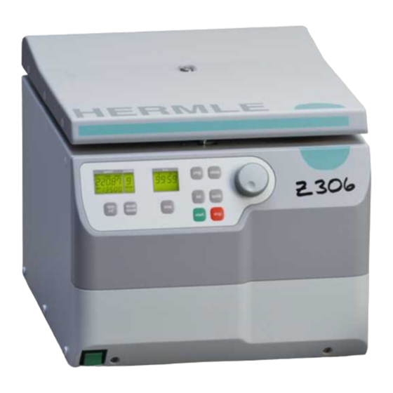
Model Z 306 is a micro processor controlled cooled laboratory centrifuge. The actuation is a three phase asynchronous motor which is controlled by frequency converter. Model Z 306 has an independent error detection program, displaying possible errors and therefore supporting the trouble shooting process. -
Page 9: Control Board
The control board consists of one plate. The board can only be exchanged completely. If there is a defect you have to exchange the complete board. All signal lines lead to the control board. The PCB controls the entire centrifuge. Figure 2: Control board © Hermle Labortechnik GmbH Service Manual Z 306... -
Page 10: Lcd Display
Display field – „rpm/rcf“ Display field – „acc/dec“ Display field – „time“ Messages/logos of the display fields: „close“ „decel“ „open“ „radius“ „rotor“ „program“ „Rotor-No. “ „error“ „rpm“ „service“ „rcf“ h m s „accel“ © Hermle Labortechnik GmbH Service Manual Z 306... -
Page 11: Control Panel
/ Deceleration intensity time centrifugation time lid release quick short running start start centrifugation stop stop centrifugation prog calling stored programs store program store © Hermle Labortechnik GmbH Service Manual Z 306... -
Page 12: Frequency Converter
As soon as the lid is closed the rotor number will be indicated in the speed display (see figure 3). Transponder Figure 6 Figure 7 © Hermle Labortechnik GmbH Service Manual Z 306... -
Page 13: Over Speed Protection
The switch may never be bypassed. The lid lock is unlatched by an electro motor, receiving its signal from the control board. The actual state is indicated in the display (see M1, M2). Figure 9 © Hermle Labortechnik GmbH Service Manual Z 306... -
Page 14: Imbalance Detection
The unit stops when the oscillating motions are too strong. Setup data specified by the manufacturer for rotors controlled by the movement sensor cannot be changed. Chapter 9.2.7 Chapter 9.2.10 Figure 10 Figure 11 © Hermle Labortechnik GmbH Service Manual Z 306... -
Page 15: Operation/Service Menu
Valid for the units of the category with frequency converter. Units: 20r, Z 216MK, Z 32HK, Z 326K, Z 326, Z 36HK, Z 366, Z 306, Seta2 The operation menu helps the service personnel to locate defects. It is divided in two parts, which are graded in several areas again from chapter 9.3.1 to 9.3.2.2. - Page 16 Now in the display “acc/dec“ (A-2) the word “service“ (M12) will flash. Only as long as this word is flashing, you can scroll through the further submenus with the potentiometer (1). You have to repeat this step continously to enter the different submenus! © Hermle Labortechnik GmbH Service Manual Z 306...
-
Page 17: Submenu Motor Starts
• Activate the operation menu as described in chapter 9.3.1. • Turn the potentiometer (1) until the special digit “service H“ appears in the display “acc/dec” (A-2). Figure 15 Inside the display “rpm/rcf“ (A-1) now the duty cycle is indicated. © Hermle Labortechnik GmbH Service Manual Z 306... -
Page 18: Submenu Running Time Of The Motor
• Activate the operation menu as described in chapter 9.3.1. • Turn the potentiometer (1) until the special digit ”service S“ appears in the display „acc/dec” (A-2). Figure 17 In the display “rpm/rcf“ (A-1) the actual software status is indicated now. © Hermle Labortechnik GmbH Service Manual Z 306... -
Page 19: Submenu Software Status Of The Frequency Converter
• Now the last 99 occurred error messages are indicated in the display “rpm/rcf“ (A-1). Whereas the first two digits describe the place number and the last two digits do describe the occurred error. Look at chapter 10.2.3 "Errors that may be indicated in the LCD display". © Hermle Labortechnik GmbH Service Manual Z 306... -
Page 20: Submenu Setup Of The Signal Transmitter
"start" (9) to store all parameters. Otherwise the setups were all for nothing. If the storage has been successful in the display “rpm/rcf“ (A-1) the value of the imbalance sensor and the word “StorE“ are indicated. Figure 21 © Hermle Labortechnik GmbH Service Manual Z 306... -
Page 21: Submenu Setup Of The Keypad Tone
"start" (9) to store all parameters. Otherwise the setups were all for nothing. If the storage has been successful in the display “rpm/rcf“ (A-1) the value of the imbalance sensor and the word “StorE“ are indicated. Figure 23 © Hermle Labortechnik GmbH Service Manual Z 306... -
Page 22: Submenu Setup Volume Of The Signal Generator
"start" (9) to store all parameters. Otherwise the setups were all for nothing. If the storage has been successful in the display “rpm/rcf“ (A-1) the value of the imbalance sensor and the word “StorE“ are indicated. © Hermle Labortechnik GmbH Service Manual Z 306... -
Page 23: Submenu Setup Of The Signal Melody
"start" (9) to store all parameters. Otherwise the setups were all for nothing. If the storage has been successful in the display “rpm/rcf“ (A-1) the value of the imbalance sensor and the word “StorE“ are indicated. Figure 27 © Hermle Labortechnik GmbH Service Manual Z 306... -
Page 24: Submenu Check And Calibration Of The Imbalance Sensor
Attention: After all points have been reviewed and/or set up, you have to press shortly the key "start" (9) to store all parameters. Otherwise the setups were all for nothing. If the storage has been © Hermle Labortechnik GmbH Service Manual Z 306... -
Page 25: Submenu Indication Of The Imbalance Value Of The Rotor
• In the bottom line of the display “rpm/rcf“ the real imbalance value is indicated. In the top line the rotor number is indicated (in this case 221.17 V?). V? stands for rotor version. © Hermle Labortechnik GmbH Service Manual Z 306... -
Page 26: Submenu Keyboard Test
• Turn the potentiometer (1) until the special digit “service d“ appears in the display “acc/dec“ (A-2) EXAMPLE: Revision number 2, with automatically check (in this case (on)), (see figure 33). Abbildung 33 © Hermle Labortechnik GmbH Service Manual Z 306... -
Page 27: Activation Of The Service Menu (Part2)
• Turn the potentiometer (1) until the special digit “service t“ appears in the display “acc/dec“ (A-2). • Examples: Figure 35 • By pressing the key rpm/rcf (4) the display “rpm/rcf“ (A-1) is now activated and you can setup the respective option with the potentiometer (1). © Hermle Labortechnik GmbH Service Manual Z 306... -
Page 28: Submenu Adjustment Of The Operation Mode
(1). • As we have already mentioned in the beginning this letters will appear when you switch on the unit during the normal operation (see chapter 9.3.1). © Hermle Labortechnik GmbH Service Manual Z 306... -
Page 29: Submenu Adjustment/Correction Of The Imbalance Cut Off Value
Activate the operation menu as described under 9.3.2 „Activation of the service menu (Part 2)“. Press the button "accel/decel" (5). Turn the potentiometer (1) until the special digit „U“ appears in the display "acc/dec" (A-2). figure 38 © Hermle Labortechnik GmbH Service Manual Z 306... -
Page 30: Hermle Labortechnik Gmbh Service Manual Z
Otherwise the setups were all for nothing. If the storage has been successful in the display „rpm/rcf“ the value of the imbalance sensor and the word „StorE“ are indicated. figure 39 © Hermle Labortechnik GmbH Service Manual Z 306... -
Page 31: Mounting Support
• Loosen the 5 screws under the control panel and pull away the panel forward. Use therefore the pictured tools. Remove the interface cable on the control board. (connection between control board and control panel). Figure 40 remove Loosen and pull away forward Figure 41 © Hermle Labortechnik GmbH Service Manual Z 306... -
Page 32: Replacing The Incremental Shaft Encoder (Potentiometer)
• Loosen all electrical contacts to the display on the back of the front housing. • Remove the 4 fastening screws of the display and pull away the display upwards. remove Figure 44 © Hermle Labortechnik GmbH Service Manual Z 306... -
Page 33: Replaicing The Foil Keyboard
Remove all screws on the left, right and back side and side of the housing. Remove the screws on the lid lock (see figure 46) and its electrical grounding. remove Figure 46 © Hermle Labortechnik GmbH Service Manual Z 306... -
Page 34: Replacing The Lid Gasket
ATTENTION: The lid gasket is glued at some points in case you want to reuse the same gasket you have to loosen the glued points carefully to avoid any damage. • Reassemble the unit in reverse order. © Hermle Labortechnik GmbH Service Manual Z 306... -
Page 35: Removing The Lid
• Make sure the lid rests on the lid gasket straight and continuous. Tighten the fasting screws firmly at the backside of the unit after the adjustment. 9.4.9 Replacing the aerial (antenna or rotor sensor) © Hermle Labortechnik GmbH Service Manual Z 306... -
Page 36: Replacing The Motor Resp. The Motor Rubber Bearings
U2 = black b) V2 = Brown c) W 2 = blue d) Ground This is a clamping system. Make sure, that after new connections the wires are clamped between the terminal. © Hermle Labortechnik GmbH Service Manual Z 306... - Page 37 • When tightening the motor mount screws, please pay attention the motor rubber mounts are not being twisted. • When connecting the motor with the electricity, take care of the rotating direction (Direction of arrow) on the housing. • Reassemble the unit in reverse order. © Hermle Labortechnik GmbH Service Manual Z 306...
- Page 38 When tightening the motor rubber mounts, also take care that they are not being twisted. ATTENTION: After replacing of the motor look to 9.3.1.12 for recalibration. © Hermle Labortechnik GmbH Service Manual Z 306...
-
Page 39: Replacing The Power Board
• Remove fixing screws as shown on the below picture and remove the frequency converter from the unit. remove Figure 56 • Attention: Before placing a new converter into the unit, put some heat conducting paste onto the fixing surface. Reassemble the unit in reverse order. © Hermle Labortechnik GmbH Service Manual Z 306... -
Page 40: Checkup The Imbalance Sensor
• Remove all electrical connections on the control board. • Remove the 4 screws and remove the control board. remove Figure 57 9.4.15 Replacing the break resistance • Remove the covering of the front housing as described in chapter 9.4.1. © Hermle Labortechnik GmbH Service Manual Z 306... -
Page 41: Replacing The Signal Generator
• Remove electrical connections on the control panel (see figure 59,1) Figure 59 • Go with a flat, sharp item (knife or screwdriver) under the signal transmitter and lift it up with slight efforts. © Hermle Labortechnik GmbH Service Manual Z 306... -
Page 42: Replacing The Lid Lock
• Remove the two fixing screws of the lid lock and put in the new lid lock. remove remove Figure 60 • Keep attention through adjustment of the lid lock, that the lid lies straight and continuous on the lid sealing. After adjustment tighten the screws well. © Hermle Labortechnik GmbH Service Manual Z 306... -
Page 43: Trouble Shouting
• ATTENTION: Don't put your hands in the rotor chamber as long as the rotor is still spinning! • Put the plastic stopper back in the unit again, for ongoing work. Figure 61 © Hermle Labortechnik GmbH Service Manual Z 306... -
Page 44: Description Of The Error Message System
(Position request not understood at the (between control to frequency converter), start) frequency converter is defective, control unit is defective. © Hermle Labortechnik GmbH Service Manual Z 306... - Page 45 The rotor, which is stored in the There was chosen a program, in which a program, does not match with the certain rotor is stored, but the inserted rotor is inserted rotor. another one. © Hermle Labortechnik GmbH Service Manual Z 306...
-
Page 46: Maintenance
(if available). The most suitable lubricant is the offered HERMLE High TEF oil – Order no.: 34-5147. Lubricants containing molycote and graphite are not allowed. -
Page 47: Cleaning And Disinfection Of The Unit
You can disregard the consequences of some chemical residues to plastic materials at ambient temperatures. But at the high temperatures of the autoclaving those residues may corrode and destroy the plastic. The objects must be thoroughly washed up with distilled water after the cleaning © Hermle Labortechnik GmbH Service Manual Z 306... -
Page 48: Glass Breakage
Tube racks, which are used in rotor no. 221.12 V03 have a service life up to 1 year from first use. Condition for the operating life: Proper use, damage-free condition, recommended care. © Hermle Labortechnik GmbH Service Manual Z 306... -
Page 49: Flow Diagrams
CIRCUIT DIAGRAMS 12. Flow diagrams 12.1 Flow diagram 230 V / 120 V / 50-60 Hz, page 1 Figure 63 © Hermle Labortechnik GmbH Service Manual Z 306... -
Page 50: Flow Diagram 230 V / 120 V / 50-60 Hz
CIRCUIT DIAGRAMS 12.2 Flow diagram 230 V / 120 V / 50-60 Hz, page 2 Figure 64 © Hermle Labortechnik GmbH Service Manual Z 306... -
Page 51: Control Board
CIRCUIT DIAGRAMS 12.3 Control board Figure 65 © Hermle Labortechnik GmbH Service Manual Z 306... -
Page 52: Spare Part List
(main switch) 120 V 944.026 power cord 944.032 line filter 944.051 sight glass 950.173 hinge (stainless; silver) 950.174 motor rubber mount 954.008 rubber feet 954.025 lid sealing 954.027 Table 4: Spare part list © Hermle Labortechnik GmbH Service Manual Z 306...
Need help?
Do you have a question about the Z 306 and is the answer not in the manual?
Questions and answers