
Related Manuals for Omron DST1-ID12SL-1


Summary of Contents for Omron DST1-ID12SL-1
- Page 1 Cat. No. Z904-E1-06 DeviceNet Safety DST1-series Safety I/O Terminals OPERATION MANUAL...
- Page 3 DST1-series Safety I/O Terminals Operation Manual Revised June 2011...
- Page 5 Indicates prohibited actions. OMRON Product References All OMRON products are capitalized in this manual. The word “Unit” is also capitalized when it refers to an OMRON product, regardless of whether or not it appears in the proper name of the product.
- Page 6 OMRON. No patent liability is assumed with respect to the use of the information contained herein. Moreover, because OMRON is con- stantly striving to improve its high-quality products, the information contained in this manual is subject to change without notice.
- Page 7 TABLE OF CONTENTS PRECAUTIONS ........Intended Audience ............General Precautions .
-
Page 8: Table Of Contents
DST1-ID12SL-1 ........ - Page 9 About this Manual: This manual describes the installation and operation of a DST1-series Safety I/O Terminals (referred to as the DST1 in this manual). Please read this manual carefully and be sure you understand the information provided before attempting to install or operate the DST1. Be sure to read the precautions provided in the following section.
- Page 11 WHETHER SUCH CLAIM IS BASED ON CONTRACT, WARRANTY, NEGLIGENCE, OR STRICT LIABILITY. In no event shall the responsibility of OMRON for any act exceed the individual price of the product on which liability is asserted. IN NO EVENT SHALL OMRON BE RESPONSIBLE FOR WARRANTY, REPAIR, OR OTHER CLAIMS...
- Page 12 Application Considerations SUITABILITY FOR USE OMRON shall not be responsible for conformity with any standards, codes, or regulations that apply to the combination of products in the customer's application or use of the products. At the customer's request, OMRON will provide applicable third party certification documents identifying ratings and limitations of use that apply to the products.
- Page 13 Performance data given in this manual is provided as a guide for the user in determining suitability and does not constitute a warranty. It may represent the result of OMRON's test conditions, and the users must correlate it to actual application requirements. Actual performance is subject to the OMRON Warranty and Limitations of Liability.
- Page 15 PRECAUTIONS Intended Audience ..........General Precautions .
-
Page 16: Intended Audience
It is extremely important that a PLC and all PLC Units be used for the speci- fied purpose and under the specified conditions, especially in applications that can directly or indirectly affect human life. You must consult with your OMRON representative before applying a PLC System to the above-mentioned appli- cations. - Page 17 General Precautions ■ Safety Measures When using this safety device to build systems containing safety-related components for equipment or facilities, the system must be designed with the full understanding of and conformance to international standards, such as those listed below, and/or standards in related industries. •...
- Page 18 General Precautions • Typical related international standards: ISO/DIS 12100 ISO, Safety of Machinery -- Basic Concepts and General Principles for Design IEC 61508, Safety Standard for Safety Instrumented Systems (Functional Safety of Electrical/Electronic/Programmable Electronic Safety-related Systems) xviii...
-
Page 19: Safety Precautions
Safety Precautions Safety Precautions WARNING Serious injury may possibly occur due to loss of required safety functions. Do not use test outputs of the DST1 as any safety outputs. Serious injury may possibly occur due to loss of required safety functions. Do not use DeviceNet standard I/O data or Explicit message data as any safety data. - Page 20 Safety Precautions WARNING For the DST1-MRD08SL-1, isolating transformers, such as TR1, that are used to isolate between overvoltage categories III and II must conform to IEC60742, and the insulation between the primary input and secondary output must satisfy at least the basic insulation standards of overvoltage category III. One side of the secondary output of the isolating transformer must be grounded to prevent electrical shock in case of short-circuiting to the ground or to the frame of the isolating transformer.
-
Page 21: Operating Environment Precautions
Operating Environment Precautions Control device Requirements Emergency stop switches Use approved switches with a direct opening mechanism complying with IEC/EN 60947-5-1. Door interlocking switches Use approved switches with a direct opening mechanism complying with IEC/EN 60947-5-1 and capable of switching micro-loads of 4 mA at 24 V DC. Limit switches Safety sensors Use approved sensors complying with the relevant product standards, regu-... - Page 22 Operating Environment Precautions ■ Installation/Wiring • Use the following to wire external I/O devices to the DST1. Solid wire 0.2 to 2.5 mm AWG 24 to 12 Standard (Flexible) wire 0.34 to 1.5 mm AWG 22 to 16 • Disconnect the DST1 from power supply when wiring. Devices connected to DST1 may operate unexpectedly.
-
Page 23: Additional Precautions According To Ul 1604
Additional Precautions According to UL 1604 Additional Precautions According to UL 1604 DST1-ID12SL-1 and DST1-MD16SL-1 are suitable for use in Class I, Div. 2, Group A, B, C, D or Non-Hazardous Location Only. WARNING - Explosion Hazard - Substitution of Components May Impair Suit- ability For Class I, Div. -
Page 24: Glossary
Glossary Glossary Term Description idle data Data sent when the originating application is in an inexecutable state. assembly Internal data in a device gathered as one group to be accessed externally. safety data Data with high reliability. error latch time The time period to hold an error state (control data, status data, and LED indi- cations). -
Page 25: Overview
SECTION 1 Overview Overview ........... . . 1-1-1 About the DST1-series Safety I/O Terminals . -
Page 26: Overview
Overview Section 1-1 Overview 1-1-1 About the DST1-series Safety I/O Terminals The DST1-series Safety I/O Terminals support the DeviceNet Safety protocol and provide various functions for the Safety System. The DST1-series Safety I/O Terminals allow the user to construct a safety control/network system that meets the requirements for Safety Integrity Level (SIL) 3 according to IEC 61508 (Functional Safety of Electrical/Electronic/ Programmable Electronic Safety-related Systems) and the requirements for Safety Category 4 accord-... -
Page 27: Dst1-Series Safety I/O Terminals Features
Section 1-1 Overview 1-1-2 DST1-series Safety I/O Terminals Features Safety Inputs • Semiconductor output devices such light curtains can be connected as well as contact output devices such as emergency stop switches. • Faults in external wiring can be detected. •... - Page 28 Overview Section 1-1 System Startup and Error Recovery Support • Error information can be checked by using the error log function or the indicators on the front of the DST1-series Safety I/O Terminals. • The DST1-series Safety I/O Terminal’s safety I/O data and internal status information can be monitored from a Standard PLC by allocating the infor- mation in the standard Master.
-
Page 29: Standard Models
1-2-1 Input Terminals and I/O Terminals Model I/O capacity Safety Test outputs Safety outputs inputs Semiconductor Relay outputs outputs DST1-ID12SL-1 12 inputs 4 outputs (See note.) DST1-MD16SL-1 8 inputs 4 outputs 8 outputs (See note.) DST1-MRD08SL-1 4 inputs 4 outputs 4 outputs (See note.) -
Page 30: Functions
Functions Supported by All DST1-series Terminals Function Description Reference Safety I/O Safety inputs The DST1-ID12SL-1 supports 12 safety inputs. 1-4 Descrip- The DST1-MD16SL-1 supports 8 safety inputs. tion of Safety The DST1-MRD08SL-1 supports 4 safety inputs. Functions The DST1-XD0808SL-1 supports 8 safety inputs. -
Page 31: Input Terminals And I/O Terminals
(Cat. No. accessed unintentionally. Z905) Note Except for the DST1-MRD08SL-1. 1-3-2 Input Terminals and I/O Terminals The following functions are provided by the DST1-ID12SL-1, DST1-MD16SL- 1, and DST1-MRD08SL-1. Function Description Reference Maintenance Network power supply volt- The present, bottom, and peak values for the network power supply volt-... -
Page 32: Logic Terminals
Section 1-3 Functions 1-3-3 Logic Terminals These functions are provided by the DST1-XD0808SL-1. Function Description Reference Logic Functions Logic functions The DST1-XD0808SL-1 provides basic logic parameters, such as AND 1-5 Logic and OR. This enables direct control of local outputs from local inputs, Functions reducing reaction time. -
Page 33: Description Of Safety Functions
Section 1-4 Description of Safety Functions Description of Safety Functions 1-4-1 DST1-series Safety I/O Terminals Safe State The following status is treated as the safe state by the DST1-series Safety I/O Terminals. • Safety outputs: OFF • Output data to network: OFF Outputs to network: OFF DeviceNet Safe... -
Page 34: Safety Inputs
Section 1-4 Description of Safety Functions 1-4-2 Safety Inputs Safety Inputs with Test Pulses (Input Circuit Diagnosis) A test output is used in combination with a safety input. Specify the corre- sponding test output terminal to use as the test source. The test output termi- nal is used as a power supply to connect an external input device to the safety input terminal. - Page 35 Description of Safety Functions Section 1-4 If an error is detected, safety input data and individual safety input status will turn OFF. * Normal 24 V External device Safety input 0 Remote I/O data Status of safety input 0 * Error 24 V External device Error...
- Page 36 Description of Safety Functions Section 1-4 The following table shows the relation between terminal input and remote I/O data. Dual channel mode Input terminals Remote I/O data Meaning of data Safety input Safety input Dual Channel Equiv- alent Dual Channel Com- plementary...
- Page 37 Section 1-4 Description of Safety Functions Dual Channels, Equivalent The status is treated as normal when both channels are ON or OFF. If one channel is ON and the other channel is OFF, it will be treated as an error, and the safety input data and the individual safety input status will turn OFF for both inputs.
- Page 38 Description of Safety Functions Section 1-4 Dual Channels, Complementary The status is treated as normal when one channel is ON and the other chan- nel is OFF. When both channels are ON or both channels are OFF, it is treated as an error, and the safety input data and the individual safety input status will turn OFF for both inputs.
-
Page 39: Safety Outputs
Section 1-4 Description of Safety Functions Input Delays ON Delay An input signal is treated as being OFF during the ON delay setting time (0 to 126 ms, in increments of 6 ms) after the input contact’s rising edge. The input will turn ON only if the input contact remains ON after the ON delay time has elapsed. -
Page 40: I/O Status Data
Section 1-4 Description of Safety Functions The status is treated as normal when both channels are normal. If an error is detected for one channel, the safety output data and the individual safety out- put status will turn OFF for both channels. * Normal OUT0 OUT1... -
Page 41: Logic Functions
Logic Functions Section 1-5 Output Monitors The outputs monitors indicated the actual ON/OFF status of the safety out- puts. Logic Functions The DST1-XD0808SL-1 supports logic functions. 1-5-1 Overview Safety logic control can be easily performed by setting a combination of I/O data from local I/O terminals and remote I/O data from a Standard Master or Safety Master with the logic operations supported by the DST1-XD0808SL-1. -
Page 42: Parameters That Can Be Set
Section 1-5 Logic Functions 1-5-3 Parameters That Can Be Set Data That Can Be Set for Input Condition Signals Name Option Setting range Input condi- Remote I/O Remote safety I/O data (received from Safety Master through the tion signal network) Input 0 to Input 5 Safety input terminals IN0 to IN5 The following data is used for remote I/O data. - Page 43 Section 1-5 Logic Functions Data That Can Be Set for Safety Input Logic Result or Remote I/O Name Option Setting range Output condi- Remote I/O Data received from Safety Master or Standard Master through the tion signal network IN0 to IN5 Safety input logic operation result The following data is used for remote I/O data.
- Page 44 Section 1-5 Logic Functions Data That Can Be Set for Additional Outputs Additional output data Description Same value as safety output Outputs the same value as any safety output terminal. terminal Inverse value of safety output Outputs the inverse value of any safety output terminal. terminal Reset required indication Outputs a 1-Hz pulsing signal to trigger a reset input.
-
Page 45: Monitoring Functions
Monitoring Functions Section 1-6 Monitoring Functions DST1-series Safety I/O Terminals hold a variety of status information inter- nally. This information can be monitored using the Network Configurator. 1-6-1 Monitoring Status Description The status of the DST1-series Safety I/O Terminals can be monitored using the Network Configurator. - Page 46 Monitoring Functions Section 1-6 Device Status The device status is displayed. Alarm/Warning Errors and warning that have occurred in the device are displayed. Click the Detail Button to identify the error. The icon will be displayed for alarms and the icon for warnings.
-
Page 47: Monitoring Parameters
Section 1-6 Monitoring Functions 1-6-2 Monitoring Parameters Description The I/O status of a DST1-series Safety I/O Terminal can be monitored using the Network Configurator. If the configuration fails or if an error occurs in any I/O, monitoring this information enables the user to determine the cause of the error. - Page 48 Monitoring Functions Section 1-6 Test Output Terminal Status Item Description Test Output Value Output value of the test output. Test Output Status Evaluation result of the test output. “Alarm” is displayed if an error occurs. Reason for Test Output The cause of the error is displayed. Alarm Muting Lamp Status “Alarm”...
-
Page 49: Monitoring The Error History
Section 1-6 Monitoring Functions 1-6-3 Monitoring the Error History Description The error history of a DST1-series Safety I/O Terminal can be monitored using the Network Configurator. Ten records can be saved internally in a DST1-series Safety I/O Terminal. When the number of errors exceeds the number of records, the oldest records will be deleted. - Page 50 Section 1-6 Monitoring Functions Error History Display Items Item Description Description Provides error details. Time The total device operation time when the error occurred. DST1- series Safety I/O Terminals do not support this function and 0 will always be displayed. (Refer to 1-7-2 Monitoring the Run Hours.) Saving the Error History The error history information can be saved in CSV format.
-
Page 51: Maintenance Functions Of Dst1-Series Safety I/O Terminals
Maintenance Functions of DST1-series Safety I/O Terminals Section 1-7 Maintenance Functions of DST1-series Safety I/O Terminals DST1-series Safety I/O Terminals support the same maintenance functions as DRT2-series Smart Slaves, which are Standard Slaves. 1-7-1 Network Power Supply Voltage Monitor Description DST1-series Safety I/O Terminals always monitor the present, minimum, and maximum values of the network power supply voltage. - Page 52 Section 1-7 Maintenance Functions of DST1-series Safety I/O Terminals Monitoring Using the Network Configurator The user can monitor the present, maximum, and minimum values of the net- work power voltage in the General Status using any of the following methods: 1.
-
Page 53: Monitoring The Run Hours
Section 1-7 Maintenance Functions of DST1-series Safety I/O Terminals 1-7-2 Monitoring the Run Hours Description A DST1-series Safety I/O Terminal totals the number of hours the internal cir- cuit power is supplied and internally saves it in non-volatile memory. If the cumulative time reaches the set threshold value, the Unit Maintenance Flag will turn ON in the General Status. - Page 54 Section 1-7 Maintenance Functions of DST1-series Safety I/O Terminals Setting the Threshold Run Hours Using the Network Configurator Set the threshold value in the Threshold Run hours Field of the General Parameter Group. If the threshold value is set to 0, the threshold value will not be checked.
- Page 55 Section 1-7 Maintenance Functions of DST1-series Safety I/O Terminals Monitoring Using the Network Configurator The user can monitor run hours in the General Status using any of the follow- ing methods: 1. Select a device and select Device - Maintenance Information from the menu bar.
-
Page 56: Last Maintenance Date
Section 1-7 Maintenance Functions of DST1-series Safety I/O Terminals 1-7-3 Last Maintenance Date Description With a DST1-series Safety I/O Terminal the last maintenance date can be recorded internally in non-volatile memory. This enables the user to easily decide the time for the next maintenance. The recorded maintenance date can be monitored using the Network Configurator or explicit messages. - Page 57 Section 1-7 Maintenance Functions of DST1-series Safety I/O Terminals Monitoring Using the Network Configurator The user can monitor the maintenance date using any of the following meth- ods: 1. Select a device and select Device - Maintenance Information from the menu bar.
-
Page 58: Monitoring The Contact Operation Counters
Section 1-7 Maintenance Functions of DST1-series Safety I/O Terminals 1-7-4 Monitoring the Contact Operation Counters Description A DST1-series Safety I/O Terminal totals the number of times each safety input contact, test output contact, and safety output contact turns ON and internally saves the data in non-volatile memory. - Page 59 Section 1-7 Maintenance Functions of DST1-series Safety I/O Terminals Setting the Contact Operation Counter Threshold Using the Network Configurator Set the Maintenance Counter Mode Choice Parameter and Threshold Mainte- nance Counter Parameter for each I/O of the safety input group, test output group, and safety output group.
- Page 60 Section 1-7 Maintenance Functions of DST1-series Safety I/O Terminals Monitoring Using the Network Configurator The user can monitor the counts for safety input status, test output status, and safety output status using any of the following methods: 1. Select a device and select Device - Maintenance Information from the menu bar.
-
Page 61: Monitoring The Total On Times
Section 1-7 Maintenance Functions of DST1-series Safety I/O Terminals 1-7-5 Monitoring the Total ON Times Description A DST1-series Safety I/O Terminal totals the time each safety input contact, test output contact, and safety output contact is ON, and saves it internally in non-volatile memory. - Page 62 Section 1-7 Maintenance Functions of DST1-series Safety I/O Terminals Measuring 0.5-second ON Time In Figure A, the actual ON time is 0.5 seconds x 3, or 1.5 seconds. Operation is ON only once when measurements are made, however, so the time is mea- sured as 1 second.
- Page 63 Section 1-7 Maintenance Functions of DST1-series Safety I/O Terminals Setting the Threshold Value for Total ON Time Using the Network Configurator Set the Maintenance Counter Mode Choice Parameter and Threshold Mainte- nance Counter Parameter for each contact of the safety input group, test out- put group, and safety output group.
- Page 64 Section 1-7 Maintenance Functions of DST1-series Safety I/O Terminals Monitoring Using the Network Configurator The user can monitor the times for safety input status, test output status, and safety output status using any of the following methods: 1. Select a device and select Device - Maintenance Information from the menu bar.
-
Page 65: Monitoring The Operation Time
Maintenance Functions of DST1-series Safety I/O Terminals Section 1-7 1-7-6 Monitoring the Operation Time Description A DST1-series Safety I/O Terminal measures the time from when a safety out- put turns ON until the safety input turns ON and internally saves the data in non-volatile memory. - Page 66 (e.g., Safety Input 0 and Safety Output 0). • In the DST1-ID12SL-1, the time is measured between two safety inputs turning ON (e.g., Safety Input 0 and Safety Input 6).
- Page 67 Section 1-7 Maintenance Functions of DST1-series Safety I/O Terminals Setting the Threshold Response Time Using the Network Configurator The Threshold Response Time is set for each pair in the Operation Time Parameter Group. If the threshold value is set to 0, the threshold value will not be checked.
- Page 68 Maintenance Functions of DST1-series Safety I/O Terminals Section 1-7 Monitoring Using the Network Configurator The user can monitor the operation time using any of the following methods: 1. Select a device and select Device - Maintenance Information from the menu bar. 2.
-
Page 69: General Procedure
SECTION 2 General Procedure General Procedure..........Installation. -
Page 70: General Procedure
Section 2-1 General Procedure General Procedure The general procedure for using the DST1-series Safety I/O Terminals is given below. Refer to the DeviceNet Operation Manual (Cat. No. W267) for the network structure and the topology. Install the DST1-series Safety I/O Terminals in the control panel. -
Page 71: Installation
Installation Section 2-2 Installation Use the DIN Track (35 mm wide) to install the DST1-series Safety I/O Termi- nals in the control panel. Wiring ducts 50 mm min. 35 mm DIN Track End Plate End Plate (PFP-M) (PFP-M) 50 mm min. Wiring ducts * Refer to the descriptions of individual DST1 models (Section 5) for dimen- sions. -
Page 72: Connecting I/O Power And I/O Cable
Section 2-3 Connecting I/O Power and I/O Cable Connecting I/O Power and I/O Cable Use the following wire sizes to wire external I/O devices. Solid wire 0.2 to 2.5 mm (AWG 24 to AWG 12) Stranded wires 0.34 to 1.5 mm (AWG 22 to AWG 16) * Refer to the descriptions of individual DST1 models (Section 5) for the termi- nal arrangement of the terminal block and wiring for external I/O. - Page 73 Section 2-3 Connecting I/O Power and I/O Cable Reference Specifications (Product Specifications from Phoenix Contact) Model of ferrule Wire dimensions Ferrule specifications Cross- Removed Overall Length of Inner Inner Dimensions length of length metal part diameter of diameter of sectional insulation L1 (mm) L2 (mm)
- Page 74 Section 2-3 Connecting I/O Power and I/O Cable IMPORTANT The two sets of power supply terminals on the DST1 can be used when wiring DST1 Units individually, e.g., to use the same power supply for both inputs and outputs. Do not wire any other Units or external devices from the I/O power supply terminals of the DST1.
-
Page 75: Connecting The Communications Connector
• When connecting the communications connector to the DST1, tighten the screws on the communications connector to 0.25 to 0.3 N⋅m. • OMRON’s S8@@Power Supplies are recommended for communications power. • Be sure to separate communications cables from high-voltage and power lines. -
Page 76: Node Address
Section 2-5 Node Address Node Address Set the node address using the two rotary switches on the front panel of the DST1-series Safety I/O Terminals. The default setting is 63. Set the tens digit of the node address (decimal) using the left rotary switch and set the ones digit using the right rotary switch. - Page 77 SECTION 3 Configuration Editing Parameters ..........3-1-1 Setting Parameters Using the Wizard .
-
Page 78: Editing Parameters
1. Select a DST1-series Safety I/O Terminal, and then select Device - Pa- rameter - Wizard. The following window will be displayed. If there are no output terminals (DST1-ID12SL-1), the window for setting input terminals will be displayed. 2. In the window above, specify the type of device to be connected to each terminal. - Page 79 Section 3-1 Editing Parameters Type Description Other 2 Safety Outputs w/o pulse Specify to connect to two outputs that do (See note.) not require pulse to be checked. Other Safety Output w/o pulse Specify to connect to one output that does not require pulse to be checked.
- Page 80 Section 3-1 Editing Parameters Type Description Door SW 2NC (See note 1.) Specify to use two inputs (both NC) from a door switch. Door SW 1NC/1NO (See note 1.) Specify to use two inputs (NC and NO) from a door switch. Door SW 1NC Specify to use one input from a door switch.
- Page 81 Section 3-1 Editing Parameters Comments for each output terminal can be edited in this window. 6. After making the settings, click the Next Button. The following dialog box will be displayed. Comments for each input terminal can be edited in this dialog box.
- Page 82 Section 3-1 Editing Parameters 8. After checking the settings, click the Finish Button. (After this, the Edit Logic Dialog Box will be displayed for the Logic Terminal (DST1-XD0808SL-1). Note Refer to the DeviceNet Safety NE0A Series Safety Network Controller Opera- tion Manual (Cat.
-
Page 83: Parameter Groups
Section 3-1 Editing Parameters 3-1-2 Parameter Groups DST1-series Safety I/O Terminal parameters are classified into groups as shown in the following diagram. • Double-click a group name or click the icon to display or hide that group. • Parameter settings for a particular terminal can be batch copied to the parameters for another terminal. -
Page 84: General Parameter Group
Section 3-1 Editing Parameters 3-1-3 General Parameter Group This section describes parameters in the general parameter group. Item Settings Description Default Safety Output Error 0 to 65,530 ms This parameter is common to all the safety 1,000 ms Latch Time outputs. - Page 85 Section 3-1 Editing Parameters Item Settings Description Default Execution Mode After Establishing Starts in Idle Mode after the configuration After Estab- (DST1-XD0808SL-1 Safety I/O Connection has been completed. Goes into RUN Mode lishing Safety only) when safety I/O communications are started. I/O Connec- tion Auto Execution...
-
Page 86: Safety Input Parameter Groups
Section 3-1 Editing Parameters 3-1-4 Safety Input Parameter Groups This section describes parameters in the safety input parameter groups. The safety input parameters are grouped by terminal number. Item Settings Description Default Off On Delay 0 to 126 ms Sets the OFF/ON delay time. 0 ms (in 6-ms increments) On Off Delay... - Page 87 Section 3-1 Editing Parameters Item Settings Description Default Dual Channel Safety 0 to 65,530 ms Sets the time to monitor the logic discrepancy 0 ms Input Discrepancy Time in the dual channel input logic. (in 10-ms increments) I/O Comment 32 characters max. Sets an I/O comment for the safety input.
-
Page 88: Test Output Parameter Groups
Section 3-1 Editing Parameters 3-1-5 Test Output Parameter Groups This section describes parameters in the test output groups. The test output parameters are grouped by terminal number. Item Settings Description Default Test Output Mode Not Used. The corresponding test output is not used. Not Used. -
Page 89: Safety Output Parameter Groups
Section 3-1 Editing Parameters 3-1-6 Safety Output Parameter Groups This section describes parameters in the safety output groups. The safety output parameters are grouped by terminal number. Item Settings Description Default Safety Output Channel Not Used. The safety output is not used. (External out- Not Used. -
Page 90: Operation Time Parameter Groups
Section 3-1 Editing Parameters 3-1-7 Operation Time Parameter Groups This section describes parameters in the safety input/output operation time groups. The operation time parameters are grouped by the terminal numbers to be paired. Item Settings Description Default Equipment Name 32 characters max. Sets a comment for the operation time to None monitor. -
Page 91: Safety Input Logic Parameter Groups (Safety Input Logic)
Section 3-1 Editing Parameters 3-1-8 Safety Input Logic Parameter Groups (Safety Input Logic) Safety input parameter groups can be set only for the DST1-XD0808SL-1. Set these parameters using the Safety Logic Wizard. Parameter name Value Description Default Input Condition Not Used Does not perform logic operations with safety Not Used input terminals. -
Page 92: Safety Output Logic Parameter Groups (Safety Output Logic)
Section 3-1 Editing Parameters 3-1-9 Safety Output Logic Parameter Groups (Safety Output Logic) Safety output parameter groups can only be set for the DST1-XD0808SL-1. Set these parameters using the Safety Logic Wizard. Parameter name Value Description Default Output Condition Output from network Uses a safety output terminal as a network output. -
Page 93: 3-1-10 Editing I/O Comments
Section 3-1 Editing Parameters 3-1-10 Editing I/O Comments I/O comments can be edited by setting the safety input terminals and safety output terminals. The edited comments here are used as I/O tags in the Logic Editor. In the following procedure, separate I/O tags for safety input terminals and safety output terminals are edited in one window. -
Page 94: Remote I/O Allocations
Section 3-2 Remote I/O Allocations Remote I/O Allocations 3-2-1 I/O Allocations The DST1-series Safety I/O Terminals internally store I/O data. Connection paths can be set using the Network Configurator to allocate I/O data for the Master Unit. Be sure to set the required connection paths. 3-2-2 I/O Data The DST1-series Safety I/O Terminals store the following data. - Page 95 Remote I/O Allocations Section 3-2 Data Description Input data General Status Data DST1-ID12SL-1 DST1-XD0808SL-1 DST1-MD16SL-1 DST1-MRD08SL-1 Bit 0 Safety Input Power Status Flag 0: Input power supply ON 1: Input power supply OFF Bit 1 Safety Output Power Status Flag...
-
Page 96: I/O Data Supported By Each Model
30 Safety Controllers total can communicate with the DST1-series Safety I/O Terminals. Up to two safety connections can be used with the DST1-XD0808SL-1. DST1-ID12SL-1 The default values for the I/O assembly data are as follows: Safety connections: Default (Assembly instance number) Safety input assembly 1 (Instance No. - Page 97 Section 3-2 Remote I/O Allocations Network Configurator Inputs Outputs setting √ √ √ √ √ Safety input assembly 5 Input 4 √ √ √ √ √ √ Safety input assembly 6 Input 4 √ √ √ Standard output assembly Output 1 √...
- Page 98 Remote I/O Allocations Section 3-2 The following I/O data can be selected from the Network Configurator. Network Configurator Inputs Outputs setting √ √ √ Safety input assembly 1 Input 1 √ √ √ √ √ √ Safety input assembly 2 Input 2 √...
- Page 99 Section 3-2 Remote I/O Allocations The following I/O data can be selected from the Network Configurator. Network Configurator Inputs Outputs setting √ √ √ Safety input assembly 1 Input 1 √ √ √ √ √ √ Safety input assembly 2 Input 1 √...
- Page 100 Section 3-2 Remote I/O Allocations Network Configurator Inputs Outputs setting √ √ √ Safety input assembly 1 Input 1 √ √ √ √ √ Safety input assembly 2 Input 2 √ √ √ √ √ √ √ √ √ √ √...
-
Page 101: I/O Assembly Data
Input 2 Input 1 Input 0 Reserved Safety Safety Safety Safety Input 11 Input 10 Input 9 Input 8 Applicable Terminal: DST1-ID12SL-1 Instance Byte Bit 7 Bit 6 Bit 5 Bit 4 Bit 3 Bit 2 Bit 1 Bit 0 (hex) - Page 102 Bit 7 Bit 6 Bit 5 Bit 4 Bit 3 Bit 2 Bit 1 Bit 0 (hex) General Status Applicable Terminal: DST1-ID12SL-1, DST1-MD16SL-1, DST1-MRD08SL-1 Instance Byte Bit 7 Bit 6 Bit 5 Bit 4 Bit 3 Bit 2 Bit 1...
- Page 103 Section 3-2 Remote I/O Allocations Instance Byte Bit 7 Bit 6 Bit 5 Bit 4 Bit 3 Bit 2 Bit 1 Bit 0 (hex) Safety Safety Safety Safety Safety Safety Safety Safety Input 7 Input 6 Input 5 Input 4 Input 3 Input 2 Input 1...
- Page 104 Section 3-2 Remote I/O Allocations Instance Byte Bit 7 Bit 6 Bit 5 Bit 4 Bit 3 Bit 2 Bit 1 Bit 0 (hex) Safety Safety Safety Safety Safety Safety Safety Safety Input 7 Input 6 Input 5 Input 4 Input 3 Input 2 Input 1...
- Page 105 Test Test Test Test Output 3 Output 2 Output 1 Output 0 Status Status Status Status Applicable Terminal: DST1-ID12SL-1 Instance Byte Bit 7 Bit 6 Bit 5 Bit 4 Bit 3 Bit 2 Bit 1 Bit 0 (hex) General Status...
- Page 106 Section 3-2 Remote I/O Allocations Instance Byte Bit 7 Bit 6 Bit 5 Bit 4 Bit 3 Bit 2 Bit 1 Bit 0 (hex) Safety Safety Safety Safety Safety Safety Safety Safety Input 7 Input 6 Input 5 Input 4 Input 3 Input 2 Input 1...
- Page 107 Bit 0 (hex) Reserved Standard Standard Standard Standard Output 3 Output 2 Output 1 Output 0 Applicable Terminal: DST1-ID12SL-1, DST1-MD16SL-1, DST1-MRD08SL-1 Instance Byte Bit 7 Bit 6 Bit 5 Bit 4 Bit 3 Bit 2 Bit 1 Bit 0 (hex)
-
Page 108: Changing Default Standard I/O Assembly Data (Dst1-Xd0808Sl-1 Only)
Section 3-2 Remote I/O Allocations Instance Byte Bit 7 Bit 6 Bit 5 Bit 4 Bit 3 Bit 2 Bit 1 Bit 0 (hex) Safety Safety Safety Safety Safety Safety Safety Safety Output 7/ Output 6/ Output 5/ Output 4/ Output 3/ Output 2/ Output 1/... - Page 109 Section 3-2 Remote I/O Allocations CS/CJ-series DeviceNet Unit A CS/CJ-series DeviceNet Unit can change I/O assembly data, so there is no need to use this function to change the default standard I/O assembly data. Even if this function is used to change the data, the CS/CJ-series DeviceNet Unit settings will be given priority.
- Page 110 Section 3-2 Remote I/O Allocations...
-
Page 111: Specifications
SECTION 4 Specifications Specifications ..........4-1-1 Common Specifications . -
Page 112: Specifications
Model Communications current Current consumption for I/O Weight consumption power supply (See note.) DST1-ID12SL-1 100 mA at 24 V DC 70 mA at 24 V DC 420 g DST1-MD16SL-1 110 mA at 24 V DC 50 mA at 24 V DC for inputs... -
Page 113: Devicenet Communications Specifications
Section 4-1 Specifications • Output device power terminal I/O power supply current that can be supplied to V and G terminals = out- put current (of number of points used) + current consumption for I/O power supply IMPORTANT Do not supply a current that exceeds the I/O power supply current to the I/O power terminal. -
Page 114: Indicators
Section 4-2 Indicators Indicators 4-2-1 MS/NS Indicators This section describes the meanings of MS and NS indicators for the DST1- series Safety I/O Terminals. The MS (Module Status) indicator displays the status of a node on the net- work. The NS (Network Status) indicator displays the status of the entire network. The MS and NS indicators can be green or red and they can be ON, flashing, or OFF. -
Page 115: In Pwr/Out Pwr Indicators
Section 4-2 Indicators 4-2-3 IN PWR/OUT PWR Indicators The IN PWR and OUT PWR indicators indicate the status of the I/O power supplied to the DST1-series Safety I/O Terminals. LED Indicators Color Status Meaning IN PWR Green Normal status of input power Input power is not supplied. - Page 116 Section 4-2 Indicators...
-
Page 117: Dst1 Series Specifications
DST1-ID12SL-1 ........ -
Page 118: Dst1-Id12Sl-1
Residual voltage 1.2 V max. between each output terminal and V Leakage current 0.1 mA max. 5-1-3 Nomenclature The following figure shows the names of the parts of the DST1-ID12SL-1. Node address switches LED indicators DeviceNet communications connector Terminal blocks •... -
Page 119: Internal Circuits And Terminal Arrangement
Section 5-1 DST1-ID12SL-1 5-1-4 Internal Circuits and Terminal Arrangement The following figure shows the internal circuits of the DST1-ID12SL-1. DC-DC converter (non-isolated) Internal circuits DeviceNet physical Shield layer V− I/O power Safety input circuits Test output circuits supply (current sinking) -
Page 120: Dimensions
Section 5-1 DST1-ID12SL-1 I/O Power Supply Circuit Test Output Circuit T0...T3 Internal Safety Input Circuit Circuit IN0...IN11 5-1-5 Dimensions The following figures show the dimensions of the DST1-ID12SL-1 (unit: mm). 71.4... -
Page 121: Dst1-Md16Sl-1
Section 5-2 DST1-MD16SL-1 DST1-MD16SL-1 5-2-1 Safety Input Specifications The following table gives the safety input specifications for the DST1- MD16SL-1. Item Specifications Input type Sinking input (PNP) ON voltage 11 VDC min. between each input terminal and G0 OFF voltage 5 VDC max. -
Page 122: Nomenclature
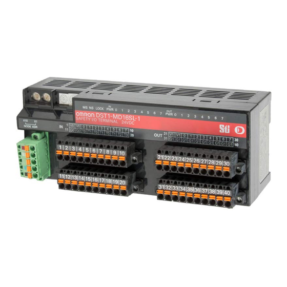
Section 5-2 DST1-MD16SL-1 5-2-4 Nomenclature The following figure gives the names of the parts of the DST1-MD16SL-1 Node address switches LED indicators DeviceNet communications connector Terminal blocks • Refer to 4-2 Indicators for information on the LED indicators. • Refer to 2-4 Connecting the Communications Connector for information on the DeviceNet communications connector. - Page 123 Section 5-2 DST1-MD16SL-1 The following table shows the terminal arrangement of the terminal blocks on the DST1-MD16SL-1. Terminals Names Functions Power terminals for the input devices and test outputs. (24 VDC) 11,12 3 to 10 IN0 to IN7 Terminals for safety inputs 13 to 20 T0 to T3 Terminals for test outputs...
-
Page 124: Dimensions
Section 5-2 DST1-MD16SL-1 5-2-6 Dimensions The following figures show the dimensions of the DST1-MD16SL-1 (unit: mm). 71.4... -
Page 125: Dst1-Mrd08Sl-1
Section 5-3 DST1-MRD08SL-1 DST1-MRD08SL-1 5-3-1 Safety Input Specifications The following table gives the safety input specifications for the DST1- MRD08SL-1. Item Specifications Input type Sinking input (PNP) ON voltage 11 VDC min. between each input termi- nal and G0 OFF voltage 5 VDC max. -
Page 126: Nomenclature
Section 5-3 DST1-MRD08SL-1 5-3-4 Nomenclature The following figure shows the names of the parts of the DST1-MRD08SL-1. Node address switches LED indicators Safety relays DeviceNet communications connector Terminal blocks • Refer to 4-2 Indicators for information on the LED indicators. •... - Page 127 Section 5-3 DST1-MRD08SL-1 Terminals Names Functions 7 to 10 T0 to T3 Terminals for test outputs 13 to 16 21, 22 Power terminals for driving internal relays. (24 VDC) 31, 32 23 to 30 OUT0 to OUT3 Terminals for safety outputs 33 to 40 C0 to C3 Outputs of terminals 23/33 (OUT0) and 24/34 (OUT0e) are the same.
- Page 128 Section 5-3 DST1-MRD08SL-1 !WARNING For the DST1-MRD08SL-1, isolating transformers, such as TR1, that are used to isolate between overvoltage categories III and II must conform to IEC60742, and the insulation between the primary input and secondary output must sat- isfy at least the basic insulation standards of overvoltage category III. One side of the secondary output of the isolating transformer must be grounded to prevent electrical shock in case of short-circuiting to the ground or to the frame of the isolating transformer.
-
Page 129: Dimensions
Section 5-3 DST1-MRD08SL-1 5-3-6 Dimensions The following figures show the dimensions of the DST1-MRD08SL-1 (unit: mm). 83.2... -
Page 130: Dst1-Xd0808Sl-1
Section 5-4 DST1-XD0808SL-1 DST1-XD0808SL-1 5-4-1 Safety Input Specifications The following table gives the safety input specifications for the DST1- XD0808SL-1. Item Specifications Input type Sinking input (PNP) ON voltage 11 VDC min. between each input termi- nal and G0 OFF voltage 5 VDC max. -
Page 131: Internal Circuits And Terminal Arrangement
Section 5-4 DST1-XD0808SL-1 Node address switches Operation display section DeviceNet communications connector I/O connectors • Refer to 4-2 Indicators for details on the LED indicators. • Refer to 2-4 Connecting the Communications Connector for details on the DeviceNet communications connector. •... - Page 132 Section 5-4 DST1-XD0808SL-1 Terminals Names Functions 1, 2 Power terminals for input devices and test outputs (24 VDC) 11, 12 3 to 10 IN0 to IN7 Terminals for safety inputs 13 to 20 T0 to T3 Terminals for test outputs 21, 22 Power terminals for output devices (24 VDC) 31, 32...
-
Page 133: Dimensions
Section 5-4 DST1-XD0808SL-1 5-4-6 Dimensions The following figures show the dimensions of the DST1-XD0808SL-1 (unit: mm). 71.4... - Page 134 Section 5-4 DST1-XD0808SL-1...
-
Page 135: Response Performance
SECTION 6 Response Performance Reaction Time ..........6-1-1 Reaction Time Concept . -
Page 136: Reaction Time
Reaction Time Section 6-1 Reaction Time 6-1-1 Reaction Time Concept The reaction time is the maximum time required for stopping an output, taking into account errors that may occur in safety chains (logical connections for creating safety devices, consisting of input devices, control devices including remote I/O devices, and output devices). -
Page 137: Troubleshooting And Maintenance
SECTION 7 Troubleshooting and Maintenance Indicators and Error Processing ........Troubleshooting . -
Page 138: Indicators And Error Processing
Indicators and Error Processing Section 7-1 Indicators and Error Processing LOCK Description Probable cause and remedy Green Red Green Red Yellow Green Yellow Red − − − Safety I/O communications in progress (normal status) − − − − − − RUN status (DST1-XD0808SL-1 only) −... -
Page 139: Troubleshooting
Section 7-2 Troubleshooting Troubleshooting I/O errors can be read out from safety input status, test output status, and safety output status. Status data when I/O is normal: ON (1) Status data when an error occurs I/O: OFF (0) The details of errors can be read out by using explicit messages and the Net- work Configurator. -
Page 140: Test Output Errors
Section 7-2 Troubleshooting 7-2-2 Test Output Errors Code Error Probable cause Countermeasure 01 hex Configuration invalid The configuration is invalid. Configure the DST1 correctly. 02 hex Overload detected 1. Ground fault or short-circuit of an out- 1. Check the wiring. put signal line 2. -
Page 141: Safety Output Errors
Troubleshooting Section 7-2 7-2-3 Safety Output Errors Code Error Probable cause Countermeasure 01 hex Configuration invalid The configuration is invalid. Configure the DST1 correctly. 02 hex Over current detected Trouble with the connected device Replace the connected device. 03 hex Short circuit to low Ground fault of the output signal line Check the wiring. -
Page 142: Error History
Section 7-3 Error History Error History The DST1-series Safety I/O Terminals internally store up to 10 error history records. The history is updated each time an error occurs. When more than ten records exist, the oldest record will be deleted. The error history can be read using the Network Configurator. - Page 143 Section 7-3 Error History Message Countermeasure Safety Output Terminal-related Failures Cross Connection Detected at Safety Output Check the following points: Stuck-at-high Detected at Safety Output • Make sure there is no overcurrent for the output. • Make sure the output signal wire does not have an earth fault. Short Circuit to Low at Safety Output •...
-
Page 144: Maintenance
Section 7-4 Maintenance Maintenance This section describes the routine cleaning and inspection recommended as regular maintenance. Handling methods when replacing the DST1-series Safety I/O Terminals are also explained here. 7-4-1 Cleaning Clean the DST1-series Safety I/O Terminals regularly as described below to keep the network in optimal operating condition. -
Page 145: Replacing The Dst1
After replacement, make sure that there are no errors in the new DST1. When a DST1 is being returned for repair, attach a detailed description of the problem and return the DST1 to your OMRON representative. If there is a faulty contact, try wiping the contact with a clean, lint-free cloth dampened with alcohol. - Page 146 Maintenance Section 7-4...
-
Page 147: Wiring Examples
SECTION 8 Wiring Examples Wiring and Configuration ........Examples of Wiring for Each Application . -
Page 148: Wiring And Configuration
Wiring and Configuration Section 8-1 Wiring and Configuration The following table shows input device connection methods and configuration. Connected Schematic diagram Configuration device Reset switch Connect the switch between IN0 and T0. Safety Input used as “Single Channel input” with- out test output. -
Page 149: Examples Of Wiring For Each Application
Examples of Wiring for Each Application Examples of Wiring for Each Application 8-2-1 Emergency Stop Switch Dual Channel Inputs with Manual Reset An example of the wiring and configuration when using the DST1-ID12SL-1 is shown below. Wiring E1: 24-V DC Power Supply (S8@@) - Page 150 Section 8-2 Examples of Wiring for Each Application 8-2-2 Two-Hand Input An example of the wiring and configuration when using the DST1-ID12SL-1 is shown below. Wiring E1: 24-V DC Power Supply (S8@@) S11,S12: Two-hand control switches Configuration Parameter Parameter name...
- Page 151 Examples of Wiring for Each Application Section 8-2 8-2-3 User Mode Switch Input An example of the wiring and configuration when using the DST1-ID12SL-1 is shown below. Wiring E1: 24-V DC Power Supply (S8@@) S1: User mode switch Configuration Parameter...
- Page 152 Section 8-2 Examples of Wiring for Each Application 8-2-4 Muting Lamp Output An example of the wiring and configuration when using the DST1-ID12SL-1 is shown below. Wiring E1: 24-V DC Power Supply (S8@@) L1: External muting lamp Configuration Parameter Parameter name...
- Page 153 Section 8-2 Examples of Wiring for Each Application 8-2-5 Limit Switch Dual Channel Inputs and a Manual Reset An example of the wiring and configuration when using the DST1-ID12SL-1 is shown below. Wiring E1: 24-V DC Power Supply (S8@@) S1: Safety Limit Switch (D4D or D4B)
- Page 154 Section 8-2 Examples of Wiring for Each Application 8-2-6 Safety Light Curtain Input An example of the wiring and configuration when using the DST1-ID12SL-1 is shown below. Wiring E1: 24-V DC Power Supply (S8@@) F3SN-A: Safety Light Curtain F3SN-A Receiver...
- Page 155 Section 8-2 Examples of Wiring for Each Application 8-2-7 Semiconductor Outputs for Dual Channel Mode An example of the wiring and configuration when using the DST1-MD16SL-1 is shown below. Wiring E1: 24-V DC Power Supply (S8@@) L1, L2: Loads Configuration Parameter Parameter name Value...
- Page 156 Section 8-2 Examples of Wiring for Each Application 8-2-8 Relay Outputs with Dual Channel Mode and EDM Input An example of the wiring and configuration when using the DST1- MRD08SL-1 is shown below. Wiring E1, E2: 24-V DC Power Supply (S8@@) KM1, KM2: Magnetic Contactors M: 3-phase motor F1, F2: Fuses...
-
Page 157: Logic Terminal Wiring Examples
Section 8-3 Logic Terminal Wiring Examples Logic Terminal Wiring Examples 8-3-1 Stopping Outputs by Using an Emergency Stop Switch or a Signal from a Safety Master An example of the wiring and configuration when using the DST1- XD0808SL-1 is shown below. Wiring →... - Page 158 Section 8-3 Logic Terminal Wiring Examples Operation Chart Emergency stop Emergency stop Output data ON switch released switch pressed Output data OFF ESTOP 11-12 ESTOP 21-22 Safety Output No.0 (Safety Output Data) Reset KM1-NC KM2-NC →RUN Configuration Port Safety Input Parameter Channel Mode Test Off On...
- Page 159 Section 8-3 Logic Terminal Wiring Examples...
- Page 160 Section 8-3 Logic Terminal Wiring Examples...
-
Page 161: Appendices
Note The number of bytes designated for the class ID, instance ID, and attribute ID depend on the Master Unit. When sent from an OMRON DeviceNet Master, the class ID and instance ID are 2 bytes (4 digits) each, and the attribute ID is 1 byte (2 digits). - Page 162 Appendix 1 DeviceNet Explicit Messages Service Code For normal completions, the service code specified in the command with the leftmost bit turned ON is stored as shown in the following table. Function Command service code Response service code Read data 0E hex 8E hex Write data...
- Page 163 Appendix 1 DeviceNet Explicit Messages A-1-2 Explicit Messages Reading General Status Explicit Read/ Function Command Response message write Service Class Instance Attribute Data size code General Sta- Read Reads the speci- 0E hex 95 hex 01 hex 65 hex 1 byte tus Read fied slave’s status flags (8 bits)
- Page 164 Appendix 1 DeviceNet Explicit Messages Setting and Monitoring a Safety Input Explicit Read/ Function Command Response message write Service Class Instance Attribute Data size Code Terminal Read Reads the monitor 0E hex 3D hex 01 to 0C 65 hex 1 byte Maintenance mode for mainte- 00 hex: Total ON...
- Page 165 DeviceNet Explicit Messages Appendix 1 Explicit Read/ Function Command Response message write Service Class Instance Attribute Data size Code Input Monitor Read Reads the set 0E hex 3D hex 01 to 0C 67 hex 1 byte Status for value for the total 00 hex: Within Total ON ON time (unit: s) or...
- Page 166 DeviceNet Explicit Messages Appendix 1 Setting and Monitoring the Safety Output Point Explicit Read/ Function Command Response message write Service Class Instance Attribute Data size Code Terminal Read Reads the monitor 0E hex 3B hex 01 to 08 65 hex 1 byte Maintenance mode for mainte-...
- Page 167 Appendix 1 DeviceNet Explicit Messages Explicit Read/ Function Command Response message write Service Class Instance Attribute Data size Code Output Moni- Read Reads the set 0E hex 3B hex 01 to 08 67 hex 1 byte tor Status for value for the total 00 hex: Within Total ON ON time or number...
- Page 168 DeviceNet Explicit Messages Appendix 1 Setting and Monitoring the Test Output Point Explicit Read Function Command Response message /write Service Class Instance Attribute Data size Code Terminal Main- Read Reads the monitor 0E hex 09 hex 01 to 04 65 hex 1 byte tenance Infor- mode for mainte-...
- Page 169 Appendix 1 DeviceNet Explicit Messages Explicit Read Function Command Response message /write Service Class Instance Attribute Data size Code Output Monitor Read Reads the set value 0E hex 09 hex 01 to 04 67 hex 1 byte Status for Total for the total ON 00 hex: Within ON Time or...
- Page 170 Appendix 1 DeviceNet Explicit Messages Setting and Monitoring Operation Time Explicit Read Function Command Response message /write Data size Service Class Instance Attribute Data size Code Set Value for Read Reads the monitor 0E hex 97 hex 01 to 08 67 hex 2 bytes Operation Time...
- Page 171 DeviceNet Explicit Messages Appendix 1 Setting Hold/Clear for Communications Errors (Test Output) Explicit Read Function Command Response message /write Service Class Instance Attribute Data size Code Setting for Out- Read Reads whether hold 0E hex 09 hex 01 to 04 05 hex 1 byte put Status (Hold...
- Page 172 Appendix 1 DeviceNet Explicit Messages A-1-3 Using Explicit Messages The following example shows how to use explicit messages with the DST1-series Safety I/O Terminals using a CS1W-DRM21 DeviceNet Unit (Master). Example: Reading the Monitor Status for the Operation Time Monitor Example Conditions DeviceNet Unit node address: 05 Unit number: 0...
- Page 173 Appendix 1 DeviceNet Explicit Messages Command Details • [CMND S D C] S: D01000 D (first response word): D02000 C: D00000 Contents of S Address Contents Meaning D01000 2801 hex Command code D01001 0B0E hex DST1 node address: 11 Service code: 0E hex D01002 003D hex Class ID: 003D hex...
- Page 174 Calculated values of PFD and PFH of the DST1-series Safety I/O Terminals are given in the following tables. These values must be calculated for the overall devices within the system to comply with the SIL level required for application. A-2-1 Calculated PFD Values Model Proof test interval (years) DST1-ID12SL-1 0.25 2.21E-07 4.39E-07 8.76E-07 1.76E-06 DST1-MD16SL-1 0.25...
-
Page 175: Index
DeviceNet communications connector specifications editing parameters DeviceNet explicit messages error codes DeviceNet Safety list protocol error history dimensions error processing DST1-ID12SL-1 indicators DST1-MD16SL-1 error recovery DST1-MRD08SL-1 DST1-XD0808SL-1 explicit messages application examples discrepancy time list DST1-ID12SL-1 dimensions internal circuits... - Page 176 Index general parameter group Network Configurator glossary xxiv node address nomenclature DST1-ID12SL-1 DST1-MD16SL-1 DST1-MRD08SL-1 I/O assembly data DST1-XD0808SL-1 I/O cables NS indicator I/O comments I/O data I/O indicators I/O power supply indicators OFF delay I/O status data ON delay IN PWR indicator...
- Page 177 Index safety functions terminal arrangement DST1-ID12SL-1 Safety I/O Terminals DST1-MD16SL-1 with relay outputs DST1-MRD08SL-1 safety input DST1-XD0808SL-1 safety input parameter groups test output parameter groups safety input specifications test output specifications DST1-ID12SL-1 DST1-ID12SL-1 DST1-MRD08SL-1 DST1-MD16SL-1 DST1-XD0808SL-1 DST1-MRD08SL-1 safety input terminal status...
- Page 178 Index...
-
Page 179: Revision History
Revision History The manual revision is indicated at the end of the Cat. No. printed at the lower left of back cover of the manual. Cat. No. Z904-E1-06 Revision code The following table outlines the changes made to the manual during each revision. Page numbers refer to the previous version. - Page 180 Revision History Revision code Date Revised content November 2009 Page 86: Added communications current consumption to section 4-1-2. Page 87: Changed layout of bottom table. June 2011 Page ix: Added new models to table. Page xix: Added test outputs (at three locations). Page xx: Changed switching capacity from 5 to 4 mA and added item toward bottom of page.
- Page 181 Revision History...
- Page 182 The Netherlands Fremont, CA 94555-3605 U.S.A. Tel: (31)2356-81-300/Fax: (31)2356-81-388 Tel: (1) 510-608-3400/Fax: (1) 510-744-1442 © OMRON Corporation 2005 All Rights Reserved. OMRON (CHINA) CO., LTD. OMRON ASIA PACIFIC PTE. LTD. In the interest of product improvement, Room 2211, Bank of China Tower, No.
Need help?
Do you have a question about the DST1-ID12SL-1 and is the answer not in the manual?
Questions and answers