Table of Contents
Advertisement
CJ-series Analog Input Units (CJ1W-AD041-V1/081-V1)
This section explains how to use the CJ1W-AD041-V1/081-V1 Analog Input Unit.
3-1
Specifications . . . . . . . . . . . . . . . . . . . . . . . . . . . . . . . . . . . . . . . . . . . . . . . . .
3-1-1
Specifications . . . . . . . . . . . . . . . . . . . . . . . . . . . . . . . . . . . . . . . . . .
3-1-2
Input Function Block Diagram . . . . . . . . . . . . . . . . . . . . . . . . . . . . .
3-1-3
Input Specifications . . . . . . . . . . . . . . . . . . . . . . . . . . . . . . . . . . . . .
3-2
Operating Procedure . . . . . . . . . . . . . . . . . . . . . . . . . . . . . . . . . . . . . . . . . . . .
3-2-1
Procedure Examples . . . . . . . . . . . . . . . . . . . . . . . . . . . . . . . . . . . . .
3-3
Components and Switch Settings . . . . . . . . . . . . . . . . . . . . . . . . . . . . . . . . . .
3-3-1
Indicators . . . . . . . . . . . . . . . . . . . . . . . . . . . . . . . . . . . . . . . . . . . . .
3-3-2
Unit Number Switches . . . . . . . . . . . . . . . . . . . . . . . . . . . . . . . . . . .
3-3-3
Operation Mode Switch . . . . . . . . . . . . . . . . . . . . . . . . . . . . . . . . . .
3-3-4
Voltage/Current Switch. . . . . . . . . . . . . . . . . . . . . . . . . . . . . . . . . . .
3-4
Wiring . . . . . . . . . . . . . . . . . . . . . . . . . . . . . . . . . . . . . . . . . . . . . . . . . . . . . . .
3-4-1
Terminal Arrangement . . . . . . . . . . . . . . . . . . . . . . . . . . . . . . . . . . .
3-4-2
Internal Circuitry . . . . . . . . . . . . . . . . . . . . . . . . . . . . . . . . . . . . . . .
3-4-3
Voltage Input Disconnection. . . . . . . . . . . . . . . . . . . . . . . . . . . . . . .
3-4-4
Input Wiring Example . . . . . . . . . . . . . . . . . . . . . . . . . . . . . . . . . . .
3-4-5
Input Wiring Considerations. . . . . . . . . . . . . . . . . . . . . . . . . . . . . . .
3-5
Exchanging Data with the CPU Unit . . . . . . . . . . . . . . . . . . . . . . . . . . . . . . .
3-5-1
Outline of Data Exchange. . . . . . . . . . . . . . . . . . . . . . . . . . . . . . . . .
3-5-2
Unit Number Setting. . . . . . . . . . . . . . . . . . . . . . . . . . . . . . . . . . . . .
3-5-3
Special I/O Unit Restart Bits . . . . . . . . . . . . . . . . . . . . . . . . . . . . . .
3-5-4
Fixed Data Allocations . . . . . . . . . . . . . . . . . . . . . . . . . . . . . . . . . . .
3-5-5
I/O Refresh Data Allocations . . . . . . . . . . . . . . . . . . . . . . . . . . . . . .
3-6
Analog Input Functions and Operating Procedures . . . . . . . . . . . . . . . . . . . .
3-6-1
Input Settings and Conversion Values . . . . . . . . . . . . . . . . . . . . . . .
3-6-2
Conversion Time/Resolution Setting . . . . . . . . . . . . . . . . . . . . . . . .
3-6-3
Mean Value Processing. . . . . . . . . . . . . . . . . . . . . . . . . . . . . . . . . . .
3-6-4
Peak Value Hold Function . . . . . . . . . . . . . . . . . . . . . . . . . . . . . . . .
3-6-5
Input Disconnection Detection Function . . . . . . . . . . . . . . . . . . . . .
3-7
Adjusting Offset and Gain . . . . . . . . . . . . . . . . . . . . . . . . . . . . . . . . . . . . . . .
3-7-1
Adjustment Mode Operational Flow . . . . . . . . . . . . . . . . . . . . . . . .
3-7-2
Input Offset and Gain Adjustment Procedures . . . . . . . . . . . . . . . . .
3-8
Handling Errors and Alarms . . . . . . . . . . . . . . . . . . . . . . . . . . . . . . . . . . . . . .
3-8-1
Indicators and Error Flowchart . . . . . . . . . . . . . . . . . . . . . . . . . . . . .
3-8-2
Alarms Occurring at the Analog Input Unit . . . . . . . . . . . . . . . . . . .
3-8-3
Errors in the CPU Unit . . . . . . . . . . . . . . . . . . . . . . . . . . . . . . . . . . .
3-8-4
Restarting Special I/O Units . . . . . . . . . . . . . . . . . . . . . . . . . . . . . . .
3-8-5
Troubleshooting . . . . . . . . . . . . . . . . . . . . . . . . . . . . . . . . . . . . . . . .
SECTION 3
80
80
82
82
85
86
91
92
92
93
94
95
95
96
97
98
98
99
99
100
100
101
103
106
106
108
109
112
113
114
114
116
122
122
124
126
127
127
79
Advertisement
Chapters
Table of Contents

Related Manuals for Omron CJ1W-AD041-V1


Summary of Contents for Omron CJ1W-AD041-V1
-
Page 1: Table Of Contents
CJ-series Analog Input Units (CJ1W-AD041-V1/081-V1) This section explains how to use the CJ1W-AD041-V1/081-V1 Analog Input Unit. Specifications .......... -
Page 2: Specifications
Specifications Section 3-1 Specifications 3-1-1 Specifications Item CJ1W-AD041-V1 CJ1W-AD081-V1 Unit type CJ-series Special I/O Unit Isolation (See note 1.) Between inputs and PLC signals: Photocoupler (No isolation between input signals.) External terminals 18-point detachable terminal block (M3 screws) Affect on CPU Unit cycle time 0.2 ms... -
Page 3: Input Function Block Diagram
Analog input 7 Same as above. Same as above. Analog input 8 Note There are only four analog inputs for the CJ1W-AD041-V1. 3-1-3 Input Specifications If signals that are outside the specified range provided below are input, the conversion values (16-bit binary data) used will be either the maximum or minimum value. -
Page 4: Operating Procedure
Operating Procedure Section 3-2 Operating Procedure Follow the procedure outlined below when using Analog Input Units. Installation and Settings 1,2,3... 1. Set the operation mode to normal mode. Set the DIP switch on the front panel of the Unit, or set the operation mode in DM word m+18, to normal mode. -
Page 5: Procedure Examples
Operating Procedure Section 3-2 3-2-1 Procedure Examples CJ1W-AD041-V1 CJ-series CPU Unit CJ1W-AD081-V1 AD081 IN1: 1 to 5 V IN2: 1 to 5 V MACH IN3: 4 to 20 mA Analog inputs IN4: 4 to 20 mA IN5: 0 to 10 V... -
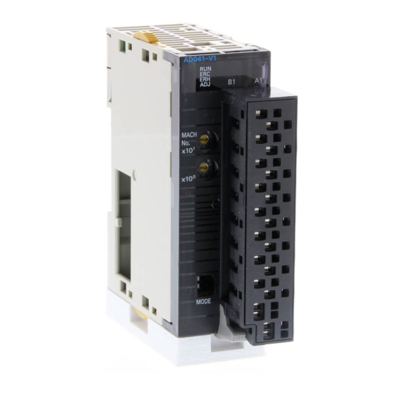
Page 6: Components And Switch Settings
Components and Switch Settings Section 3-3 Components and Switch Settings CJ1W-AD041-V1 CJ1W-AD081-V1 Front With Terminal Block With Terminal Block Removed Indicators AD081 AD081 Terminal block MACH MACH Unit number Voltage/current switches switch MODE MODE Terminal block DIN Track mounting pin... -
Page 7: Indicators
Components and Switch Settings Section 3-3 The terminal block is attached using a connector. It can be removed by lower- ing the lever at the bottom of the terminal block. The lever must normally be in the raised position. Confirm this before opera- tion. -
Page 8: Operation Mode Switch
Components and Switch Settings Section 3-3 Always turn OFF the power before setting the unit number. Use a flat-blade screwdriver, being careful not to damage the slot in the screw. Be sure not to leave the switch midway between settings. Switch Unit Words allocated in... -
Page 9: Voltage/Current Switch
Input 4 Input 3 Input 6 Input 5 MODE Input 8 Input 7 Note There are only four inputs for the CJ1W-AD041-V1. !Caution Be sure to turn OFF the power to the PLC before mounting or removing the terminal block. -
Page 10: Wiring
Section 3-4 Wiring 3-4-1 Terminal Arrangement The signal names corresponding to the connecting terminals are as shown in the following diagram. CJ1W-AD041-V1 Input 2 (+) Input 1 (+) Input 2 (–) Input 1 (–) Input 4 (+) Input 3 (+) Input 4 (–) -
Page 11: Internal Circuitry
Wiring Section 3-4 3-4-2 Internal Circuitry The following diagrams show the internal circuitry of the analog input section. Input Circuitry 15 kΩ 15 kΩ Input (+) Input circuit 250 Ω conversion 1 MΩ 15 kΩ 15 kΩ circuit Input (–) Voltage/ current input switch... -
Page 12: Voltage Input Disconnection
Wiring Section 3-4 3-4-3 Voltage Input Disconnection Connected device #1 Connected device #2 24 VDC Note If the connected device #2 in the above example outputs 5 V and the power supply is shared by 2 channels as shown in the above diagram, approximately one third of the voltage, or 1.6 V, will be input at input 1. -
Page 13: Input Wiring Example
Input 7 − Note There are only four inputs for the CJ1W-AD041-V1. Inputs 5 to 8 are not used. Note Crimp-type terminals must be used for terminal connections, and the screws must be tightened securely. Use M3 screws and tighten them to a torque of 0.5 N·m. -
Page 14: Exchanging Data With The Cpu Unit
3-5-1 Outline of Data Exchange Data is exchanged between the CPU Unit and the CJ1W-AD041-V1/081-V1 Analog Input Unit via the Special I/O Unit Area in the CIO Area (for data used to operate the Unit) and the Special I/O Unit Area in the DM Area (for data used for initial settings). -
Page 15: Unit Number Setting
Exchanging Data with the CPU Unit Section 3-5 3-5-2 Unit Number Setting The words in the Special I/O Unit Areas in the CIO Area and DM Area that are allocated to each Analog Input Unit are determined by the unit number switches on the front panel of the Unit. -
Page 16: Fixed Data Allocations
2. If two or more Special I/O Units are assigned the same unit number, a “UNIT No. DPL ERR” error (in the Programming Console) will be generat- ed (A40113 will turn ON) and the PLC will not operate. 3. Only D(m) to D(m+5) are supported by the CJ1W-AD041-V1. -
Page 17: I/O Refresh Data Allocations
I/O Refresh Data Allocations I/O refresh data for the Analog Input Unit is exchanged according to the allo- cations in the Special I/O Unit Area. SYSMAC CJ-series CPU Unit CJ1W-AD041-V1/081-V1 Analog Input Unit (I/O Refresh Data Area) (Special I/O Unit Area) Normal mode... - Page 18 The Analog Input Unit converts analog inputs specified by input numbers 1 to 8 (1 to 4 for CJ1W-AD041-V1) only. To specify the analog inputs to be used, turn ON from a Programming Device the D(m) bits in the DM Area shown in the following diagram.
- Page 19 Bits 08 to 15 in DM word m+18 can be used to set the conversion time and resolution for the CJ1W-AD041-V1 and CJ1W-AD081-V1 to increase speed and accuracy. This setting applies to analog inputs 1 to 8 (1 to 4 for the CJ1W-AD041-V1), i.e., there are not individual settings for each input. 15 14...
- Page 20 Programming Device to make the settings in D (m+2) to D (m+9) as shown in the following table. (With the CJ1W-AD041-V1, make the settings in D (m+2) to D (m+5).) DM Area...
-
Page 21: Analog Input Functions And Operating Procedures
When the load to the CPU Unit is disconnected, the Peak Value Hold Bits (bits 00 to 07 of the word n for CJ1W-AD081-V1, bits 00 to 03 of the word n for CJ1W-AD041-V1) are cleared and the peak value hold function is disabled. - Page 22 09 08 01 00 Word n+9 Only bits 00 to 03 of CIO word n are used for the CJ1W-AD041-V1. The respective bit turns ON when a disconnection is detected for a given input. When the disconnection is restored, the bit turns OFF.
- Page 23 Adjusting Offset and Gain Section 3-7 Adjusting Offset and Gain 3-7-1 Adjustment Mode Operational Flow The adjustment mode enables the input of the connected devices to be cali- brated. The offset voltage (or current) and gain voltage (or current) at the output device are entered as analog input conversion data 0000 and 0FA0 (07D0 if the range is ±10 V) respectively for a resolution of 4,000.
-
Page 24: Mean Value Processing
Adjusting Offset and Gain Section 3-7 !Caution Set the PLC to PROGRAM mode when using the Analog Input Unit in adjust- ment mode. If the PLC is in MONITOR mode or RUN mode, the Analog Input Unit will stop operating, and the input values that existed immediately before this stoppage will be retained. -
Page 25: Handling Errors And Alarms
Handling Errors and Alarms Section 3-8 Handling Errors and Alarms 3-8-1 Indicators and Error Flowchart Indicators If an alarm or error occurs in the Analog Input Unit, the ERC or ERH indica- tors on the front panel of the Unit will light. Front panel of Unit Meaning Indicator... -
Page 26: Adjustment Mode
Input Unit. Note 1. With the CJ1W-AD041-V1, the Disconnection Detection Flags are stored in bits 00 to 03. Bits 04 to 07 are not used (always OFF). 2. Disconnection detection operates for input numbers used with a range of... -
Page 27: Errors In The Cpu Unit
Handling Errors and Alarms Section 3-8 3-8-3 Errors in the CPU Unit The ERH indicator will light if an error occurs in the CPU Unit or I/O bus and I/ O refreshing with the Special I/O Units is not performed correctly, preventing the Analog Input Unit from operating. -
Page 28: Restarting Special I/O Units
Handling Errors and Alarms Section 3-8 3-8-4 Restarting Special I/O Units To restart the Analog Input Unit after changing the contents of the DM Area or correcting an error, cycle the power to the PLC or turn ON the Special I/O Unit Restart Bit.
Need help?
Do you have a question about the CJ1W-AD041-V1 and is the answer not in the manual?
Questions and answers