Omron DeviceNet DST1 Series Operation Manual
Safety i/o terminals
Hide thumbs
Also See for DeviceNet DST1 Series:
- Operation manual (105 pages) ,
- Operation manual (142 pages) ,
- Datasheet (12 pages)
Table of Contents
Troubleshooting

Subscribe to Our Youtube Channel
Related Manuals for Omron DeviceNet DST1 Series


Summary of Contents for Omron DeviceNet DST1 Series
- Page 1 Cat. No. Z904-E1-01 DeviceNet Safety DST1-ID12SL-1 Safety Input Terminal DST1-MD16SL-1 Safety I/O Terminal with Semiconductor Outputs DST1-MRD08SL-1 Safety I/O Terminal with Relay Outputs DST1-series Safety I/O Terminals OPERATION MANUAL...
- Page 5 DST1-series Safety I/O Terminals Operation Manual Produced April 2005...
-
Page 7: Omron Product References
OMRON Product References All OMRON products are capitalized in this manual. The word “Unit” is also capitalized when it refers to an OMRON product, regardless of whether or not it appears in the proper name of the product. The abbreviation “PLC” means Programmable Controller. “PC” is used, however, in some Programming Device displays to mean Programmable Controller. -
Page 8: Trademarks And Copyrights
All rights reserved. No part of this publication may be reproduced, stored in a retrieval system, or transmitted, in any form, or by any means, mechanical, electronic, photocopying, recording, or otherwise, without the prior written permission of OMRON. No patent liability is assumed with respect to the use of the information contained herein. -
Page 9: About This Manual
About this Manual About this Manual This manual describes the installation and operation of a DST1-series Safety I/O Terminals (referred to as the DST1 in this manual). Please read this manual carefully and be sure you understand the information provided before attempting to install or operate the DST1. -
Page 10: Read And Understand This Manual
WHETHER SUCH CLAIM IS BASED ON CONTRACT, WARRANTY, NEGLIGENCE, OR STRICT LIABILITY. In no event shall the responsibility of OMRON for any act exceed the individual price of the product on which liability is asserted. IN NO EVENT SHALL OMRON BE RESPONSIBLE FOR WARRANTY, REPAIR, OR OTHER CLAIMS... -
Page 11: Application Considerations
Application Considerations SUITABILITY FOR USE OMRON shall not be responsible for conformity with any standards, codes, or regulations that apply to the combination of products in the customer's application or use of the products. At the customer's request, OMRON will provide applicable third party certification documents identifying ratings and limitations of use that apply to the products. -
Page 12: Disclaimers
Performance data given in this manual is provided as a guide for the user in determining suitability and does not constitute a warranty. It may represent the result of OMRON's test conditions, and the users must correlate it to actual application requirements. Actual performance is subject to the OMRON Warranty and Limitations of Liability. -
Page 13: Precautions
It is extremely important that a PLC and all PLC Units be used for the specified purpose and under the specified conditions, especially in applications thatcan directly or indirectly affect human life. You must consult with your OMRON representative before applying a PLC System to the above-mentioned applications. - Page 14 Precautions WARNING This is the Operation Manual for the DST1-series Safety I/O Terminals. Heed the following items during system construction to ensure that safety-related components are configured in a manner that allows the system functions to sufficiently operate. Risk Assessment The proper use of the safety device described in this Operation Manual as it relates to installation conditions and mechanical performance and functions is a prerequisite for its use.
- Page 15 Precautions Safety Precautions WARNING Serious injury may possibly occur due to loss of required safety functions. Do not use test outputs of the DST1 as any safety outputs. Serious injury may possibly occur due to loss of required safety functions. Do not use DeviceNet standard I/O data or Explicit message data as any safety data.
- Page 16 Precautions Control device Requirements Emergency stop Use approved switches with a direct opening mechanism switches complying with IEC/EN 60947-5-1. Door interlocking Use approved switches with a direct opening mechanism switches complying with IEC/EN 60947-5-1 and capable of switching micro-loads of 5 mA at 24 V DC. Limit switches Safety sensors Use approved sensors complying with the relevant product...
- Page 17 Precautions Disconnect the DST1 from power supply when wiring. Devices connected to DST1 may operate unexpectedly. Apply properly specified voltages to the DST1 inputs. Applying inappropriate DC voltage and any AC voltages cause the DST1 to fail. Be sure to separate the communication cable and the I/O cable from the high-voltage/ current lines.
- Page 18 Precautions Regulation and Standards The DST1-series Safety I/O Terminals has been certified as follows by TUV Rheinland: 1. European Standards EN 954-1/12.96 EN 60204-1/12.97 EN 61000-6-2/10.01 EN 61000-6-4/10.01 EN 418/1992 2. International Standards IEC 61508 part1-7/12.98-05.00 IEC 61131-2/02.03 3. U.S.A. Standards NFPA 79-2002 ANSI RIA15.06-1999 ANSI B11.19-2003...
-
Page 19: Glossary
Glossary Glossary Term Description idle data Data sent when the originating application is in an inexecutable state. assembly Internal data in a device gathered as one group to be accessed externally. safety data Data with high reliability. error latch time The time period to hold an error state (control data, status data, and LED indications). -
Page 20: Revision History
Revision History Revision History The manual revision is indicated at the end of the Cat. No. printed at the lower left of back cover of the manual. C at. N o . Z 904-E 1-01 R evision Revision Date Modifications April 2005 First edition... -
Page 21: Table Of Contents
Table of Contents Table of Contents Notice .......................1 OMRON Product References ................1 Visual Aids ......................1 Trademarks and Copyrights ................2 About this Manual ....................3 Read and Understand this Manual ..............4 Warranty and Limitations of Liability ..............4 Application Considerations .................5 Disclaimers ......................6 Precautions ......................7... -
Page 22: Table Of Contents
Table of Contents Configuration..................2-6 Section 3 Configuration ................3-1 Set I/O Parameters..............3-2 3-1-1 General Parameters ..................3-2 3-1-2 Safety Input Parameters................3-3 3-1-3 Test Output Parameters ................3-4 3-1-4 Safety Output Parameters ................3-5 3-1-5 Operation Time Parameters ................. 3-5 Remote I/O Allocations ................ - Page 23 Table of Contents 5-3-3 Safety Output Specifications for Relay Outputs......... 5-9 5-3-4 Nomenclature..................5-10 5-3-5 Internal Circuits and Terminal Arrangement ........5-10 5-3-6 Dimensions ..................5-12 Section 6 Troubleshooting and Maintenance..........6-1 Indicators and Error Processing.............6-2 Troubleshooting ..................6-3 6-2-1 Safety Input Errors ................6-3 6-2-2 Test Output Errors ................
-
Page 24: Section 1 Overview
Section 1 Overview... -
Page 25: Overview
1-1 Overview Overview 1-1-1 About the DST1-series Safety I/O Terminals The DST1-series Safety I/O Terminals support the DeviceNet Safety protocol and provide various functions for the Safety System. The DST1-series Safety I/O Terminals allow the user to construct a safety control/network system that meets the requirements for Safety Integrity Level (SIL) 3 according to IEC 61508 (Functional Safety of Electrical/Electronic/ Programmable Electronic Safety-related Systems) and the requirements for Safety Category 4 according to EN 954-1. -
Page 26: Dst1-Series Safety I/O Terminals Features
1-1 Overview 1-1-2 DST1-series Safety I/O Terminals Features Safety Inputs • Semiconductor output devices such light curtains can be connected as well as contact output devices such as emergency stop switches. • Faults in external wiring can be detected. • Input delays (ON delays and OFF delays) can be set. •... - Page 27 1-1 Overview I/O Connector Connection/Disconnection • The I/O Connector can be connected and disconnected. • The I/O Connector is structured to prevent incorrect connection. Cage Clamp Wiring Cables can be wired without terminal screws. Maintenance Functions The DST1-series Safety I/O Terminals are equipped with Maintenance Functions such as a contact operation counter, cumulative ON time monitor, and operating time monitor.
-
Page 28: Standard Models
1-2 Standard Models Standard Models The following table shows the three models of DST1-series Safety I/O Terminals that are available: the Safety Input Terminal, Safety I/O Terminal (Semiconductor Output), and Safety Input/Output Terminal (Relay Output). I/O capacity Safety outputs Model Name Safety Test outputs... -
Page 29: Functions
1-3 Functions Functions 1-3-1 DST1-series Safety I/O Terminals Item Description Self-diagnosis Self-diagnosis is performed when power is turned ON and periodically during functions operation. When an error occurs, it is treated as a fatal error, the MS indicator will light in red, and all safety outputs and output data to the network will turn OFF. Access Control by After configuration data has been downloaded and verified, configuration data within Password... - Page 30 1-3 Functions Item Description Allocation DST1-ID12 For remote I/O communications, the user can select and allocate the patterns of SL-1 following I/O data, for which there are 15 patterns when combined: remote I/O I/O data for control communications Status data General status data Refer to Section 3-2.
-
Page 31: Safety Inputs
1-3 Functions 1-3-2 Safety Inputs Item Description Input channel Any of the following four modes can be selected according to the external input mode device for each input. Not Used The safety input is not used. (External input device not connected.) Test Pulse from Test Specifies connecting a device with a contact output in Output... -
Page 32: Test Outputs
1-3 Functions 1-3-3 Test Outputs Item Description Test output mode Any of the following five modes can be selected according to the external input device. Not Used The corresponding test output is not used. Standard Output Specifies connecting to the input for a muting lamp or PLC. Used as a monitor output. -
Page 33: Safety Outputs
1-3 Functions 1-3-4 Safety Outputs Item Description Output channel Any of the following three modes can be selected according to the external input mode device. Not Used The safety output is not used. (External output device not connected.) Safety Specifies not outputting the test pulse when the output is ON. Contact between the output signal line and the power supply (positive) when the output is OFF and ground faults can be detected. -
Page 34: Description Of Safety Functions
1-4 Description of Safety Functions Description of Safety Functions 1-4-1 DST1-series Safety I/O Terminals Safe State The following status is treated as the safe state by the DST1-series Safety I/O Terminals. • Safety outputs: OFF • Output data to network: OFF Outputs to network: OFF DeviceNet Safe... -
Page 35: Safety Inputs
1-4 Description of Safety Functions 1-4-2 Safety Inputs Test Pulse from Test Output A test output is used in combination with a safety input. Specify the corresponding test output terminal to use as the test source. The test output terminal is used as a power supply to connect an external input device to the safety input terminal. - Page 36 1-4 Description of Safety Functions If an error is detected, safety input data and individual safety input status will turn OFF. * No r mal 24 V External device Safety input 0 Remote I/O data Status of safety input 0 * Er r or 24 V External device...
- Page 37 1-4 Description of Safety Functions Setting Dual Channel Mode and Discrepancy Time The consistency between signals on two channels can be evaluated. Either of the following settings can be selected. This function monitors the time during which there is a discrepancy in the logic between the two channels set as dual channels. If the length of the discrepancy exceeds the set discrepancy time (0 to 65,530 ms, in increments of 10 ms), the safety input data and the individual safety input status will turn OFF for both inputs.
- Page 38 1-4 Description of Safety Functions Dual Channels, Equivalent The status is treated as normal when both channels are ON or OFF. If one channel is ON and the other channel is OFF, it will be treated as an error, and the safety input data and the individual safety input status will turn OFF for both inputs.
- Page 39 1-4 Description of Safety Functions Dual Channels, Complementary The status is treated as normal when one channel is ON and the other channel is OFF. When both channels are ON or both channels are OFF, it is treated as an error, and the safety input data and the individual safety input status will turn OFF for both inputs.
- Page 40 1-4 Description of Safety Functions Input Delays ON Delay An input signal is treated as being OFF during the ON delay setting time (0 to 126 ms, in increments of 6 ms) after the input contact’s rising edge. The input will turn ON only if the input contact remains ON after the ON delay time has elapsed.
-
Page 41: Safety Outputs
1-4 Description of Safety Functions 1-4-3 Safety Outputs Safety Output with Test Pulse When the output is ON, the test pulse is turned OFF for 470 µs in a cycle of 648 ms. Using this function, short-circuits between output signal lines and the power supply (positive side) and short-circuits between output signal lines can be detected. -
Page 42: Input Reaction Time
1-4 Description of Safety Functions Error Recovery All conditions below are necessary to recover from an error that has occurred in a safety output. • The cause of the error must be removed. • Error latch time must have passed. •... -
Page 43: I/O Status Data
1-4 Description of Safety Functions 1-4-6 I/O Status Data In addition to I/O data, the DST1-series Safety I/O Terminals support status data to check the I/O circuits. The status data includes the following data, for which remote I/O communications can be performed. •... -
Page 44: Section 2 General Procedure
Section 2 General Procedure... -
Page 45: General Procedure
2-1 General Procedure General Procedure The general procedure for using the DST1-series Safety I/O Terminals is given below. Refer to the DeviceNet Operation Manual (Cat.No.W267) for the network structure and the topology. Install the DST1-series Safety I/O Terminals in the control panel. ↓... -
Page 46: Installation
2-2 Installation Installation Use the DIN Track (35 mm wide) to install the DST1-series Safety I/O Terminals in the control panel. Wiring ducts 50mm min. 35mm DIN Track End Plate End Plate (PFP-M) (PFP-M) 50mm min. Wiring ducts * Refer to the descriptions of individual DST1 models (Section 5) for dimensions. IMPORTANT •... -
Page 47: Connecting I/O Power And I/O Cable
2-3 Connecting I/O Power and I/O Cable Connecting I/O Power and I/O Cable The following table shows the applicable wires for the I/O connector (when using recommended post crimp terminals). Solid wire 0.2 to 2.5 mm (AWG 24 to AWG 12) Stranded wires 0.34 to 1.5 mm AWG 22 to AWG 16) -
Page 48: Connecting The Communications Connector
When connecting the communications connector to the DST1, tighten the ⋅ screws on the communications connector to 0.25 to 0.3 N • OMRON’s S8 Power Supplies are recommended for communications power. Note • The internal power for the DST1-series Safety I/O Terminals is supplied from... -
Page 49: Node Address
2-5 Node Address Node Address Set the node address using the two rotary switches on the front panel of the DST1-series Safety I/O Terminals. The default setting is 63. Set the tens digit of the node address (decimal) using the left rotary switch and set the ones digit using the right rotary switch. - Page 50 Section 3 Configuration...
-
Page 51: 3-1 Set I/O Parameters
Remote I/O Allocations 3-1 Set I/O Parameters The DST1-series Safety I/O Terminals have five parameter groups: General Parameters, Safety Input Parameters, Test Output Parameters, Safety Output Parameters, and Operating Time Parameters. The settings in each parameter group are listed in the following tables. All parameters are set using the Network Configurator. -
Page 52: 3-1-2 Safety Input Parameters
Remote I/O Allocations 3-1-2 Safety Input Parameters Parameter name Value Description Default Off On Delay 0 to 126 ms Sets the OFF/ON delay time. 0 ms (in increments of 6 ms) Off On Delay 0 to 126 ms Sets the ON/OFF delay time. 0 ms (in increments of 6 ms) -
Page 53: 3-1-3 Test Output Parameters
Remote I/O Allocations 3-1-3 Test Output Parameters Parameter name Value Description Default Test Output Mode Not Used The corresponding test output is not Not Used used. Standard Output Specifies connecting to the input for a muting lamp or PLC. Used as a monitor output. -
Page 54: 3-1-4 Safety Output Parameters
Remote I/O Allocations 3-1-4 Safety Output Parameters Parameter name Value Description Default Safety Output Not Used The safety output is not used. Not Used Channel Mode (External output device not connected.) Safety Specifies not outputting the test pulse when the output is ON. Contact between the output signal line and the power supply (positive) when the output is OFF and ground faults can be detected. -
Page 55: Remote I/O Allocations
Remote I/O Allocations Remote I/O Allocations 3-2-1 I/O Allocations The DST1-series Safety I/O Terminals internally store I/O data. Connection paths can be set using the Network Configurator to allocate I/O data for the Master Unit. Be sure to set the required connection paths. 3-2-2 I/O Data The DST1-series Safety I/O Terminals store the following data. -
Page 56: I/O Data Supported By Each Model
Remote I/O Allocations Data Description Bit 6 Operation Time Exceeded Flag 0: Within range (all I/O values are lower than set monitor value) 1: Over range (one or more value is same as or higher than set value) Bit 7 Connected Component Maintenance Flag 0: Within range (all I/O points are lower than set monitor value) - Page 57 Remote I/O Allocations DST1-MD16SL-1 The default I/O data is as follows: Safety connections: Safety input assembly 1 (instance No. 204) and Safety output assembly 1 (instance No. 234) Standard connection: Safety input assembly 5 (instance No. 323) Inputs Outputs Network Configurator setting Safety input assembly 1 Safety input assembly 2...
-
Page 58: I/O Assembly Data
Remote I/O Allocations 3-2-4 I/O Assembly Data Input Data Instance Byte Bit 7 Bit 6 Bit 5 Bit 4 Bit 3 Bit 2 Bit 1 Bit 0 (hex) Safety Safety Safety Safety Reserved Input 3 Input 2 Input 1 Input 0 Applicable Terminal: DST1-MRD08SL-1 Instance Byte... - Page 59 Remote I/O Allocations Instance Byte Bit 7 Bit 6 Bit 5 Bit 4 Bit 3 Bit 2 Bit 1 Bit 0 (hex) Safety Safety Safety Safety Safety Safety Safety Safety Input 7 Input 6 Input 5 Input 4 Input 3 Input 2 Input 1 Input 0...
- Page 60 Remote I/O Allocations Instance Byte Bit 7 Bit 6 Bit 5 Bit 4 Bit 3 Bit 2 Bit 1 Bit 0 (hex) Safety Safety Safety Safety Safety Safety Safety Safety Input 7 Input 6 Input 5 Input 4 Input 3 Input 2 Input 1 Input 0...
- Page 61 Remote I/O Allocations Instance Byte Bit 7 Bit 6 Bit 5 Bit 4 Bit 3 Bit 2 Bit 1 Bit 0 (hex) Muting Safety Safety Safety Safety Safety Safety Lamp Reserved Input 3 Input 2 Input 1 Input 0 Status Status Status Applicable Terminal: DST1-MRD08SL-1...
- Page 62 Remote I/O Allocations Instance Byte Bit 7 Bit 6 Bit 5 Bit 4 Bit 3 Bit 2 Bit 1 Bit 0 (hex) General Status Safety Safety Safety Safety Safety Safety Safety Safety Output 7 Output 6 Output 5 Output 4 Output 3 Output 2 Output 1...
-
Page 63: Section 4 Specifications
Section 4 Specifications... -
Page 64: Specifications
4-1 Specifications Specifications 4-1-1 Common Specifications Item Specifications Communications power supply 11 to 25 V DC (Supplied from the communications connector.) voltage 20.4 to 26.4 V DC (24 V DC, −15% to +10%) I/O power supply voltage Conforms to IEC61131-2. Vibration resistance 10 to 57 Hz: 0.35 mm 57 to 150 Hz: 50 m/s... -
Page 65: Indicators
4-2 Indicators Indicators 4-2-1 MS/NS Indicators This section describes the meanings of MS and NS indicators for the DST1-series Safety I/O Terminals. The MS (Module Status) indicator displays the status of a node on the network. The NS (Network Status) indicator displays the status of the entire network. The MS and NS indicators can be green or red and they can be ON, flashing, or OFF. -
Page 66: In Pwr/Out Pwr Indicators
4-2 Indicators 4-2-3 IN PWR/OUT PWR Indicators The IN PWR and OUT PWR indicators indicate the status of the I/O power supplied to the DST1-series Safety I/O Terminals. LED Indicators Color Status Meaning IN PWR Green Normal status of input power Input power is not supplied. -
Page 67: Section 5 Dst1-Series
Section 5 DST1-series... -
Page 68: Safety Input Terminal
5-1 Safety Input Terminal Safety Input Terminal 5-1-1 Safety Input Specifications The following table gives the safety input specifications for the DST1-ID12SL-1. Item Specifications Input type Sinking input (PNP) ON voltage 11 VDC min. OFF voltage 5 VDC max. OFF current 1 mA max. -
Page 69: Internal Circuits And Terminal Arrangement
5-1 Safety Input Terminal 5-1-4 Internal Circuits and Terminal Arrangement The following figure shows the internal circuits of the DST1-ID12SL-1. DC-DC converter (non-isolated) Internal circuits DeviceNet DRAI physical layer Input power Safety input circuits Test output circuits supply circuit (current sinking) (current sourcing) The following table gives the terminal arrangement of the terminal blocks on the DST1-ID12SL-1. -
Page 70: Dimensions
5-1 Safety Input Terminal I/O Power Supply Circuit Test Output Circuit T0...T3 Internal Safety Input Circuit Circuit IN0...IN11 5-1-5 Dimensions The following figures show the dimensions of the DST1-ID12SL-1 (unit: mm). 71.4... -
Page 71: 5-2 Safety I/O Terminal With Semiconductor Outputs
5-2 Safety I/O Terminal with Semiconductor Outputs Safety I/O Terminal with Semiconductor Outputs 5-2-1 Safety Input Specifications The following table gives the safety input specifications for the DST1-MD16SL-1. Item Specifications Input type Sinking input (PNP) ON voltage 11 VDC min. OFF voltage 5 VDC max. -
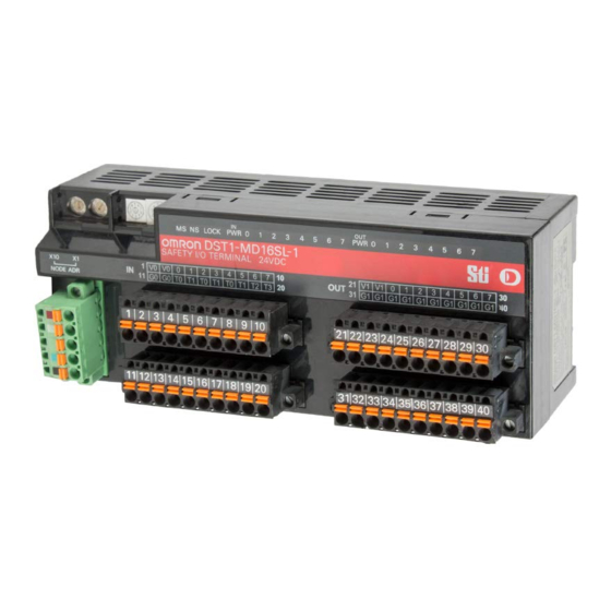
Page 72: Nomenclature
5-2 Safety I/O Terminal with Semiconductor Outputs 5-2-4 Nomenclature The following figure gives the names of the parts of the DST1-MD16SL-1 Node address switches LED indicators DeviceNet communications connector Terminal blocks • Refer to 4-2 Indicators for information on the LED indicators. •... - Page 73 5-2 Safety I/O Terminal with Semiconductor Outputs The following table shows the terminal arrangement of the terminal blocks on the DST1-MD16SL-1. Terminals Names Functions Power terminals for the input devices and test outputs. (24VDC) 11,12 3 to 10 IN0 to IN7 Terminals for safety inputs 13 to 20 T0 to T3...
-
Page 74: Dimensions
5-2 Safety I/O Terminal with Semiconductor Outputs 5-2-6 Dimensions The following figures show the dimensions of the DST1-MD16SL-1 (unit: mm). 71.4... -
Page 75: Safety I/O Terminal With Relay Outputs
5-3 Safety I/O Terminal with Relay Outputs Safety I/O Terminal with Relay Outputs 5-3-1 Safety Input Specifications The following table gives the safety input specifications for the DST1-MRD08SL-1. Item Specifications Input type Sinking input (PNP) ON voltage 11 VDC min. OFF voltage 5 VDC max. -
Page 76: Nomenclature
5-3 Safety I/O Terminal with Relay Outputs 5-3-4 Nomenclature The following figure shows the names of the parts of the DST1-MRD08SL-1. Node address switches LED indicators Safety relays DeviceNet communications connector Terminal blocks • Refer to 4-2 Indicators for information on the LED indicators. •... - Page 77 5-3 Safety I/O Terminal with Relay Outputs The following table shows the terminal arrangement of the terminal blocks on the DST1-MRD08SL-1. Terminals Names Functions 1, 2 Power terminals for the input devices, test outputs and internal relay feedback monitors.(24VDC) 11, 12 17 to 20 Common terminals.
-
Page 78: Dimensions
5-3 Safety I/O Terminal with Relay Outputs WARNING For Model DST1-MRD08SL-1, Apply only one AC line phase to the relays output. L1 L2 L3 N L1 L2 L3 N DST1- DST1- MRD08SL-1 MRD08SL-1 Load Load Load Load Correct Incorrect For Model DST1-MRD08SL-1, Insert a fuse rated at 3.15A or less for each output terminal to protect safety output contacts from welding. -
Page 79: Section 6 Troubleshooting And Maintenance
Section 6 Troubleshooting and Maintenance... -
Page 80: Indicators And Error Processing
6-1 Indicators and Error Processing Indicators and Error Processing LOCK I/O PWR Description Probable cause and remedy Green Red Green Red Yellow Green Yellow Red Safety I/O communications in progress (normal status) Standard I/O communications or message communications in progress (normal status) The DST1 performing initialization process or waiting for configuration. -
Page 81: Troubleshooting
6-2 Troubleshooting Troubleshooting I/O errors can be read out from safety input status, test output status, and safety output status. Status data when I/O is normal: ON (1) Status data when an error occurs I/O: OFF (0) The details of errors can be read out by using explicit messages and the Network Configurator. -
Page 82: Test Output Errors
6-2 Troubleshooting 6-2-2 Test Output Errors Code Error Probable cause Countermeasure Configuration invalid The configuration is invalid. Configure the DST1 correctly. Overload detected 1) Ground fault or short-circuit of 1) Check the wiring. an output signal line 2) Replace the connected 2) Trouble with the connected device. -
Page 83: Safety Output Errors
6-2 Troubleshooting 6-2-3 Safety Output Errors Code Error Probable cause Countermeasure Configuration invalid The configuration is invalid. Configure the DST1 correctly. Over current detected Trouble with the connected device Replace the connected device. Short-circuit detected Ground fault of the output signal Check the wiring. -
Page 84: Error History
6-3 Error History Error History The DST1-series Safety I/O Terminals internally store up to 10 error history records. The history is updated each time an error occurs. When more than ten records exist, the oldest record will be deleted. The error history can be read using the Network Configurator. -
Page 85: Maintenance
6-4 Maintenance Message Countermeasure Total On Time or Contact Operation Counter Exceeded Threshold Operation Time Exceeded Threshold Unit Conduction Time Exceeded Threshold Network PS Voltage Fell Below Threshold Output PS Voltage Low Check the following items. - Are cables broken? Input PS Voltage Low - Is the power voltage within specifications? Maintenance... -
Page 86: Replacing The Dst1
After replacement, make sure that there are no errors in the new DST1. When a DST1 is being returned for repair, attach a detailed description of the problem and return the DST1 to your OMRON representative. If there is a faulty contact, try wiping the contact with a clean, lint-free cloth dampened with alcohol. -
Page 87: Section 7 Wiring Examples
Section 7 Wiring Examples... -
Page 88: Wiring And Configuration
7-1 Wiring and Configuration Wiring and Configuration The following table shows input device connection methods and configuration. Connected Schematic diagram Configuration device Reset switch Connect the switch between IN0 and T0. Safety Input used as “Single Channel input” without test output. Test output used as power supply output. -
Page 89: Examples Of Wiring For Each Application
7-2 Examples of Wiring for Each Application Examples of Wiring for Each Application 7-2-1 Emergency Stop Switch Dual Channel Inputs with Manual Reset An example of the wiring and configuration when using the DST1-ID12SL-1 is shown below. Wiring E1: 24-V DC Power Supply (S8 S1: Emergency Stop Switch (A165E or A22E) (positive opening mechanism) S2: Reset switch... -
Page 90: Two-Hand Input
7-2 Examples of Wiring for Each Application 7-2-2 Two-Hand Input An example of the wiring and configuration when using the DST1-ID12SL-1 is shown below. Wiring E1: 24-V DC Power Supply (S8 S11,S12: Two-hand control switches → → Configuration Parameter Parameter Name Value Group Safety Input 0... -
Page 91: User Mode Switch Input
7-2 Examples of Wiring for Each Application 7-2-3 User Mode Switch Input An example of the wiring and configuration when using the DST1-ID12SL-1 is shown below. Wiring E1: 24-V DC Power Supply S1: User mode switch Configuration Parameter Parameter name Value group Safety Input 0... -
Page 92: Muting Lamp Output
7-2 Examples of Wiring for Each Application 7-2-4 Muting Lamp Output An example of the wiring and configuration when using the DST1-ID12SL-1 is shown below. Wiring E1: 24-V DC Power Supply (S8 L1: External muting lamp Configuration Parameter Parameter name Value group Test Output 3... -
Page 93: Limit Switch Dual Channel Inputs And A Manual Reset
7-2 Examples of Wiring for Each Application 7-2-5 Limit Switch Dual Channel Inputs and a Manual Reset An example of the wiring and configuration when using the DST1-ID12SL-1 is shown below. Wiring E1: 24-V DC Power Supply (S8 S1: Safety Limit Switch (D4D or D4B) (positive opening mechanism) S2: Limit switch S3: Reset switch... -
Page 94: Safety Light Curtain Input
7-2 Examples of Wiring for Each Application 7-2-6 Safety Light Curtain Input An example of the wiring and configuration when using the DST1-ID12SL-1 is shown below. Wiring E1: 24-V DC Power Supply (S8 F3SN-A: Safety Light Curtain F3SN-A Receiver Emitter Configuration Parameter Parameter name... -
Page 95: Semiconductor Outputs For Dual Channel Mode
7-2 Examples of Wiring for Each Application 7-2-7 Semiconductor Outputs for Dual Channel Mode An example of the wiring and configuration when using the DST1-MD16SL-1 is shown below. Wiring E1: 24-V DC Power Supply (S8 L1, L2: Loads Configuration Parameter Parameter Name Value Group... -
Page 96: Relay Outputs With Dual Channel Mode And Edm Input
7-2 Examples of Wiring for Each Application 7-2-8 Relay Outputs with Dual Channel Mode and EDM Input An example of the wiring and configuration when using the DST1-MRD08SL-1 is shown below. Wiring E1, E2: 24-V DC Power Supply (S8 KM1, KM2: Magnetic Contactors M: 3-phase motor F1, F2: Fuses Configuration... -
Page 97: Appendices
Appendices... -
Page 98: Appendix 1: Devicenet Explicit Messages
Note: The number of bytes designated for the class ID, instance ID, and attribute ID depend on the Master Unit. When sent from an OMRON DeviceNet Master, the class ID and instance ID are 2 bytes (4 digits) each, and the attribute ID is 1 byte (2 digits). - Page 99 Appendix 1: DeviceNet Explicit Messages Service Code For normal completions, the service code specified in the command with the leftmost bit turned ON is stored as shown in the following table. Function Command service code Response service code Read data 10 hex 90 hex Write data...
-
Page 100: A-1-2 Explicit Messages
Appendix 1: DeviceNet Explicit Messages A-1-2 Explicit Messages Reading General Status Command Explicit Read/ Function Response Service Class Instance Attribute message write Data size code General Read Reads the − Status Read specified slave’s 0E hex 95 hex 01 hex 65 hex 1 byte status flags (8 bits) - Page 101 Appendix 1: DeviceNet Explicit Messages Setting and Monitoring a Safety Input Command Explicit Read/ Function Response Service Class Instance Attribute message write Data size Code Terminal Read Reads the monitor 1 byte Maintenance mode for 00 hex: Total ON Information maintenance 01 to 0C time mode...
- Page 102 Appendix 1: DeviceNet Explicit Messages Command Explicit Read/ Function Response Service Class Instance Attribute message write Data size Code Safety Input Read Reads the cause 0: No error Cause of for the normal flag 01 hex: Con- Error (1 to 12) specified figuration invalid Information by the Instance ID...
- Page 103 Appendix 1: DeviceNet Explicit Messages Command Explicit Read/ Function Response Service Class Instance Attribute message write Data size Code Output Total Reset Resets the total ON ON Time or time or number of Contact contact operations 01 to 08 05 hex 66 hex Operation for time output (1 to...
- Page 104 Appendix 1: DeviceNet Explicit Messages Setting and Monitoring the Test Output Point Command Explicit Read/ Function Response Service Class Instance Attribute message write Data size Code Terminal Read Reads the monitor 1 byte Maintenance mode for 00 hex: Total ON Information maintenance 01 to 04...
- Page 105 Appendix 1: DeviceNet Explicit Messages Command Explicit Read/ Function Response Service Class Instance Attribute message write Data size Code Safety Output Read Reads the cause for 0 = No error Cause of Error the normal flag (1 to 01 hex: Con- Information 8) specified by the figuration invalid...
- Page 106 Appendix 1: DeviceNet Explicit Messages Setting Hold/Clear for Communications Errors (Test Output) Command Explicit Read/ Function Response Service Class Instance Attribute message write Data size Code Setting for Output Read Reads whether hold Status (Hold or or clear is set as the Clear) after output status after a Communications...
-
Page 107: A-1-3 Using Explicit Messages
Appendix 1: DeviceNet Explicit Messages A-1-3 Using Explicit Messages The following example shows how to use explicit messages with the DST1-series Safety I/O Terminals using a CS1W-DRM21 DeviceNet Unit (Master). Example: Reading the Monitor Status for the Operation Time Monitor Example Conditions DeviceNet Unit node address: 05 Unit number: 0... - Page 108 Appendix 1: DeviceNet Explicit Messages Command Details • [CMND S D C] S: D01000 D (first response word): D02000 C: D00000 Contents of S Address Contents Meaning D01000 2801 hex Command code D01001 0B0E hex DST1 node address: 11 Service code: 0E hex D01002 003D hex Class ID: 003D hex...
-
Page 109: Appendix 2: Calculated Values Of Pfd And Pfh
Appendix 2: Calculated Values of PFD and PFH Appendix 2: Calculated Values of PFD and PFH Calculated values of PFD and PFH of the DST1-series Safety I/O Terminals are given in the following tables. These values must be calculated for the overall devices within the system to comply with the SIL level required for application. - Page 110 Index explicit messages, A-2 application examples, A-11 cleaning, 6-7 list, A-4 communications connector, 2-5 configuration, 2-6 configuration lock indicator, 4-3 features, 1-3 configuration status, 4-3 ferrules, 2-4 current consumption, 4-2 list of models, 2-4 functions password protection, 1-11 DeviceNet communications safety, 1-11 connector, 2-5 Safety I/O Terminals, 1-6...
- Page 111 DST1-MRD08SL-1, 5-9 relay outputs, 5-9 parameters semiconductor outputs, 5-5 general, 3-2 safety outputs, 1-10, 1-18 I/O, 3-2 errors, 6-5 operation time, 3-5 test pulses, 1-18 safety input, 3-3 safety precautions, 11 safety output, 3-5 self-diagnosis functions, 1-11 test output, 3-4 semiconductor outputs password protection, 1-11 dual channel mode, 7-9...
- Page 112 The Netherlands Tel:(31)2356-81-300 Fax:(31)2356-81-388 OMRON ELECTRONICS LLC 1 East Commerce Drive, Schaumburg, IL 60173 U.S.A. Tel:(1)847-843-7900/Fax:(1)847-843-8568 OMRON ASIA PACIFIC PTE. LTD. 83 Clemenceau Avenue, #11-01, UE Square, Singapore 239920 Tel:(65)6835-3011/Fax:(65)6835-2711 OMRON (CHINA) CO., LTD. Room 2211, Bank of China Tower,...
- Page 113 Authorized Distributor: Cat. No. Z904-E1-01 Note: Specifications subject to change without notice. Printed in Japan This manual is printed on 100% recycled paper.
- Page 114 Cat. No. Z904-E1-01 OPERATION MANUAL DST1-series Safety I/O Terminals...
Need help?
Do you have a question about the DeviceNet DST1 Series and is the answer not in the manual?
Questions and answers