Table of Contents
Troubleshooting

Related Manuals for Omron DEVICENET SAFETY - 04-2005


Summary of Contents for Omron DEVICENET SAFETY - 04-2005
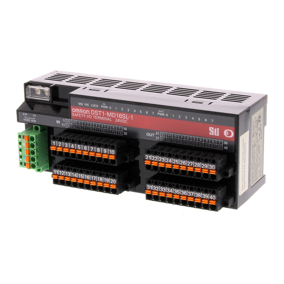
- Page 1 Cat.No. Z904-E2-01 DeviceNet Safety DST1-ID12SL-1 Safety Input Terminal DST1-MD16SL-1 Safety I/O Terminal with Semiconductor Outputs DST1-MRD08SL-1 Safety I/O Terminal with Relay Outputs DST1-series Safety I/O Terminals OPERATION MANUAL...
- Page 3 DST1-series Safety I/O Terminals Operation Manual Produced April 2005...
-
Page 5: Notice
Indicates prohibited actions. OMRON Product References All OMRON products are capitalized in this manual. The word "Unit" is also capitalized when it refers to an OMRON product, regardless of whether or not it appears in the proper name of the product. -
Page 7: About This Manual
WHETHER SUCH CLAIM IS BASED ON CONTRACT, WARRANTY, NEGLIGENCE, OR STRICT LIABILITY. In no event shall the responsibility of OMRON for any act exceed the individual price of the product on which liability is asserted. IN NO EVENT SHALL OMRON BE RESPONSIBLE FOR WARRANTY, REPAIR, OR OTHER CLAIMS... - Page 8 The following are some examples of applications for which particular attention must be given. This is not intended to be an exhaustive list of all possible uses of the products, nor is it intended to imply that the uses listed may be suitable for the products: •...
-
Page 9: Precautions
Unit and keep this manual close at hand for reference during operation. ! Warning It is extremely important that a PLC and all PLC Units be used for the specified purpose and under the spec- ified conditions, especially in applications thatcan directly or indirectly affect human life. You must consult... - Page 10 Moving or Transferring Devices or Equipment When moving or transferring devices or equipment, be sure to include this Operation Manual to ensure that the person to whom the device or equipment is being moved or transferred will be able to operate it properly. •...
-
Page 11: Safety Precautions
DC24V line do NOT touch the safety outputs accidentally or unintentionally. Serious injury may possibly occur due to loss of required safety functions. Ground the 0V line of the power supply for external output devices so that the devices do Not turn ON when the safety output line is grounded. -
Page 12: Precautions For Safe Use
Precautions for Safe Use Handle with care Do not drop the DST1 to the ground or excessive vibration or mechanical shocks. The DST1 may be dam- aged and may not function properly. Installation and storage environment Do not use or store the DST1 in any of the following locations. -
Page 13: Additional Precautions According To Ul 1604
Be cautious not to have you injured when dismantling the DST1. Additional Precautions According to UL 1604 DST1-ID12SL-1 and DST1-MD16SL-1 are suitable for use in Class I, Div. 2, Group A, B, C, D or Non-Haz- ardous Location Only. WARNING - Explosion Hazard - Substitution of Components May Impair Suitability For Class I, Div. 2. -
Page 15: Table Of Contents
1-3-2 Safety Inputs ........25 1-3-3 Test Outputs . - Page 16 Remote I/O Allocations ........46...
- Page 17 Section 7: Wiring Examples Wiring and Configuration ........80 Examples of Wiring for Each Application .
- Page 18 Table of contents...
-
Page 19: Section 1: Overview
1-3-2 Safety Inputs ........25 1-3-3 Test Outputs . -
Page 20: Overview
Input delays (ON delays and OFF delays) can be set. • Pairs of related local inputs can be set to Dual Channel Mode in order to be compliant with the Category 4 standards. When Dual Channel Mode is set, the input data patterns and the time discrepancy between input sig- nals can be evaluated. - Page 21 Relay Outputs • Pairs of related output terminals can be set to Dual Channel Mode in order to be compliant with the Cat- egory 4 standards. • When Dual Channel Mode is set, the output data patterns can be evaluated.
-
Page 22: Standard Models
Relay Outputs Each test output can be set to function as a test output or a standard output. Test outputs are used in combination with a safety input. Broken wires in an external indicator can be detected for terminal T3 only. -
Page 23: Functions
Self-diagnosis is performed when power is turned ON and periodically during opera- tions tion. When an error occurs, it is treated as a fatal error, the MS indicator will light in red, and all safety outputs and output data to the network will turn OFF. - Page 24 I/O comments The user can assign a name for each I/O contact on the DST1 (up to 32 characters each) and record it in the DST1. The connected device can be checked for each I/O contact, allowing faulty devices to be identified during remote maintenance.
-
Page 25: Safety Inputs
OFF after the OFF delay time has elapsed. This helps prevent chat- tering of the input contacts. Input error latch The OFF status is held for at least the input error latch time (0 to 65,530 ms, in increments time of 10 ms) when the individual safety input status turns OFF. -
Page 26: Test Outputs
ON. Output error The OFF status is held for at least the output error latch time (0 to 65,530 ms, in incre- latch time ments of 10 ms) when the individual safety output status turns OFF. -
Page 27: Description Of Safety Functions
Self-diagnosis is performed when the power is turned ON and periodically during operation. If an error oc- curs, it will be treated as a fatal error (the MS indicator will light in red), and the safety outputs and output data to the network will turn OFF. -
Page 28: Safety Inputs
A test output is used in combination with a safety input. Specify the corresponding test output terminal to use as the test source. The test output terminal is used as a power supply to connect an external input device to the safety input terminal. - Page 29 If the length of the discrepancy exceeds the set discrepancy time (0 to 65,530 ms, in increments of 10 ms), the safety input data and the individual safety input status will turn OFF for both inputs.
- Page 30 Dual Channels, Equivalent The status is treated as normal when both channels are ON or OFF. If one channel is ON and the other chan- nel is OFF, it will be treated as an error, and the safety input data and the individual safety input status will turn OFF for both inputs.
- Page 31 The status is treated as normal when one channel is ON and the other channel is OFF. When both channels are ON or both channels are OFF, it is treated as an error, and the safety input data and the individual safety input status will turn OFF for both inputs.
-
Page 32: Safety Outputs
Safety Output with Test Pulse When the output is ON, the test pulse is turned OFF for 470 s in a cycle of 648 ms. Using this function, short- circuits between output signal lines and the power supply (positive side) and short-circuits between output signal lines can be detected. -
Page 33: Input Reaction Time
1-4-4 Input Reaction Time The input delay is the time from when an input signal is changed to when the new signal status is sent to the network. Max. Input Reaction Time: 16.2ms + setting value of ON/OFF delay Note: Refer to the System Configuration Manual (Z905) for system reaction time. -
Page 34: I/O Status Data
1-4-6 I/O Status Data In addition to I/O data, the DST1-series Safety I/O Terminals support status data to check the I/O circuits. The status data includes the following data, for which remote I/O communications can be performed. • Normal Flags (ON when there is no faults in the internal circuit and the external wiring) •... -
Page 35: Section 2: General Procedure
General Procedure ........ -
Page 36: General Procedure
Make settings for the DST1-series Safety I/O Terminals. Refer to Section 3: Configuration (page 41). The baud rate of the entire system is determined by the baud rate of the Master Unit. The baud rate does not need to be set for each DST1-series Safety I/O Terminals. -
Page 37: Installation
Installation Use the DIN Track (35 mm wide) to install the DST1-series Safety I/O Terminals in the control panel. Wiring ducts 50mm min. 35mm DIN Track End Plate End Plate (PFP- M) (PFP- M) 50mm min. Wiring ducts Note: Refer to the descriptions of individual DST1 models (Section 5: DST1-series (page 59)) for dimensions. -
Page 38: Connecting I/O Power And I/O Cable
Use the ferrules with insulating collars conforming to DIN 46228-4. Ferrules with similar appearance but not conforming to the standard may not match the terminal blocks of the DST1-series Safety I/O Terminals. (The wire dimensions shown below are rough dimensions. Confirm before application.) Note: Use wires of the same diameter for any two-wire ferrules that are used. -
Page 39: Connecting The Communications Connector
Set the node address using the two rotary switches on the front panel of the DST1-series Safety I/O Termi- nals. The default setting is 63. Set the tens digit of the node address (decimal) using the left rotary switch and set the ones digit using the right rotary switch. A value between 00 and 63 can be set. - Page 40 Section 2: General Procedure...
-
Page 41: Section 3: Configuration
Remote I/O Allocations ........46... -
Page 42: Set I/O Parameters
The DST1-series Safety I/O Terminals have five parameter groups: General Parameters, Safety Input Pa- rameters, Test Output Parameters, Safety Output Parameters, and Operating Time Parameters. The settings in each parameter group are listed in the following tables. All parameters are set using the Net- work Configurator. -
Page 43: Safety Input Parameters
IMPORTANT: When the Safety Input Channel Mode is set to Test Pulse from Test Out, specify the test out- put to use for the test source and set the Test Output Channel Mode of the test output to Pulse Test Output. -
Page 44: Test Output Parameters
Test Output Channel Mode is set to Standard Output or Muting Lamp Output. I/O Comment 32 characters max. Sets an I/O comment for the test output. The None I/O comment set here is used as the I/O tag in the Logic Editor. -
Page 45: Operation Time Parameters
3-1-5 Operation Time Parameters Parameter name Value Description Default Equipment Name 32 characters max. Sets a comment for the operation time to None monitor. Threshold 0 to 65,535 ms (in Sets the threshold value for the operation 0 ms Response Time increments of 1 ms) time. -
Page 46: Remote I/O Allocations
I/O Allocations The DST1-series Safety I/O Terminals internally store I/O data. Connection paths can be set using the Net- work Configurator to allocate I/O data for the Master Unit. Be sure to set the required connection paths. 3-2-2 I/O Data The DST1-series Safety I/O Terminals store the following data. -
Page 47: I/O Data Supported By Each Model
Refer to 3-2-4 I/O Assembly Data (page 49) for data arrangements. From among the I/O data, safety connections for up to four items, including one output, can be allocated for the Master Unit and standard connections for up to two items can be allocated for the Master Unit. - Page 48 DST1-MD16SL-1 The default I/O data is as follows: Safety connections: Safety input assembly 1 (instance No. 204) and Safety output assembly 1 (instance No. 234) Standard connection: Safety input assembly 5 (instance No. 323) Network Configurator Inputs Outputs setting Safety input assembly 1...
-
Page 49: I/O Assembly Data
Bit 7 Bit 6 Bit 5 Bit 4 Bit 3 Bit 2 Bit 1 Bit 0 (hex) General Status Applicable Terminal: DST1-ID12SL-1, DST1-MD16SL-1, DST1-MRD08SL-1 • Instance Byte Bit 7 Bit 6 Bit 5 Bit 4 Bit 3 Bit 2 Bit 1... - Page 50 Input 5 Input 4 Status Status Status Status Status Status Status Status Muting Reserved Lamp Status Applicable Terminal: DST1-ID12SL-1 • Instance Byte Bit 7 Bit 6 Bit 5 Bit 4 Bit 3 Bit 2 Bit 1 Bit 0 (hex) Safety...
- Page 51 Input 0 Input 3 Input 2 Input 1 Input 0 Status Status Status Status Muting Reserved Safety Safety Safety Safety Lamp Output 3 Output 2 Output 1 Output 0 Status Status Status Status Status Applicable Terminal: DST1-MRD08SL-1 3-2 Remote I/O Allocations...
- Page 52 Output 1 Output 0 Monitor Monitor Monitor Monitor Monitor Monitor Monitor Monitor Muting Reserved Lamp Status Applicable Terminal: DST1-MRD08SL-1 • Instance Byte Bit 7 Bit 6 Bit 5 Bit 4 Bit 3 Bit 2 Bit 1 Bit 0 (hex) Safety...
- Page 53 Bit 0 (hex) Reserved Standard Standard Standard Standard Output 3 Output 2 Output 1 Output 0 Applicable Terminal: DST1-ID12SL-1, DST1-MD16SL-1, DST1-MRD08SL-1 • Instance Byte Bit 7 Bit 6 Bit 5 Bit 4 Bit 3 Bit 2 Bit 1 Bit 0...
- Page 54 Section 3: Configuration...
-
Page 55: Section 4: Specifications
4-2-4 I/O Indicators ........58... -
Page 56: Specifications
Combination of multi-drop and T-branch connections (for trunk or branch lines) Baud rate 125 kbps, 250 kbps, or 500 kbps Communications media Special 5-wire cable (2 signal lines, 2 power lines, 1 shield line) Communications distances Baud rate Network length Branch line length Total branch line... -
Page 57: Indicators
Configuration has not been performed. : Lit : Flashing : Not lit 4-2-3 IN PWR/OUT PWR Indicators The IN PWR and OUT PWR indicators indicate the status of the I/O power supplied to the DST1-series Safe- ty I/O Terminals. LED Indicators Color Status Meaning... -
Page 58: I/O Indicators
4-2-4 I/O Indicators The I/O indicators show the ON/OFF and error status of I/O. Note: The indicators are not lit while the DST1-series Safety I/O Terminals is being configured. Name Color Status Meaning IN0 to INn Yellow Safety input ON. - Page 59 Safety Input Terminal ........
-
Page 60: Section 5: Dst1-Series
Refer to 4-2 Indicators (page 57) for information on the LED indicators. • Refer to 2-4 Connecting the Communications Connector (page 39) for information on the DeviceNet communications connector. • Refer to 5-1-4 Internal Circuits and Terminal Arrangement (page 61) for information on the terminal blocks. Section 5: DST1-series... -
Page 61: Internal Circuits And Terminal Arrangement
Inputpower Safetyinputcircuits Testoutputcircuits supplycircuit (currentsinking) (currentsourcing) The following table gives the terminal arrangement of the terminal blocks on the DST1-ID12SL-1 Terminals Names Functions 1, 2 Power terminals for the input devices and test outputs. (24VDC) 11, 12 35 to 40 Common terminals The terminals 11, 12 and 35 to 40 are internally connected. -
Page 62: Dimensions
• I/O Power Supply Circuit Test Output Circuit T0...T3 Internal Safety Input Circuit Circuit IIN0...IN11 5-1-5 Dimensions The following figures show the dimensions of the DST1-ID12SL-1 (unit: mm). 71.4 Section 5: DST1-series... -
Page 63: Safety I/O Terminal With Semiconductor Outputs
Leakage current 0.1 mA max. IMPORTANT: In case that a safety output is configured as Safety pulsed test, while this output is in an ON state, the signal sequence shown below is output continuously to enable diagnosis. Confirm the response times of the devices connected to the safety outputs so that the devices do not malfunction due to the OFF pulse. -
Page 64: Internal Circuits And Terminal Arrangement
• Refer to 2-4 Connecting the Communications Connector (page 39) for information on the DeviceNet communications connector. • Refer to 5-2-5 Internal Circuits and Terminal Arrangement (page 64) for information on the terminal blocks. 5-2-5 Internal Circuits and Terminal Arrangement The following figure shows the internal circuits of the DST1-MD16SL-1. -
Page 65: Dimensions
OUT0 ...OUT7 IMPORTANT: Power supply terminal V1 for the outputs is internally monitored. Supply the voltage in the specified range (20.4 to 26.4 VDC). If the voltage is supplied outside this range, voltage will not be supplied to the output circuits. -
Page 66: Safety I/O Terminal With Relay Outputs
(at approx. 7,200 operations/h) Electrical life 100,000 operations min. expectancy (at rated load and approx. 1,800 operations/h) 5-3-4 Nomenclature The following figure shows the names of the parts of the DST1-MRD08SL-1. Node address switches LED indicators Safety relays DeviceNet communications connector Terminal blocks •... -
Page 67: Internal Circuits And Terminal Arrangement
• Refer to 5-3-5 Internal Circuits and Terminal Arrangement (page 67) for information on the terminal blocks. 5-3-5 Internal Circuits and Terminal Arrangement The following figure shows the internal circuits of the DST1-MRD08SL-1. DC-DC converter (non-isolated) Internal circuits DeviceNet DRAI... - Page 68 IMPORTANT: • Supply power to both V0 and V1. The states of the relay contacts are internally monitored from the power supply of V 0.
-
Page 69: Dimensions
5-3-6 Dimensions The following figures show the dimensions of the DST1-MRD08SL-1 (unit: mm). 83.2 5-3 Safety I/O Terminal with Relay Outputs... - Page 70 Section 5: DST1-series...
-
Page 71: Section 6: Troubleshooting And Maintenance
Cleaning ........77... -
Page 72: Indicators And Error Processing
(trunk and branch lines) correct? Are cables broken or loose? Are Terminating Resistors connected to both ends of the trunk line only? Is noise interference excessive? BusOff status (communi- Check the following items cations stopped due to and restart the DST1. -
Page 73: Troubleshooting
The details of errors can be read out by using explicit messages and the Network Configurator. Note: For I/O error latch time settings, the OFF status is maintained for at least the error latch time (0 to 65,530 ms, in increments of 10 ms) when individual safety input status turns OFF. -
Page 74: Test Output Errors
OFF. (See error note.) 05 hex: Error in the other dual channel input Note: The instance numbers for safety inputs 0 to 11 are 1 to 12 (01 to 0C hex), respectively. 6-2-2 Test Output Errors Code Error Probable cause Countermeasure... -
Page 75: Safety Output Errors
06 hex: Internal relay relevant circuit error 07 hex: Relay failure 08 hex: Dual channel violation 09 hex: Cross connec- tion detected Note: The instance numbers for safety outputs 0 to 7 are 1 to 8 (01 to 08 hex), respectively. 6-2 Troubleshooting... -
Page 76: Error History
Output data error at Safety Output Check the program to see if output data of dual channels are the same. Stuck-at-high Detected at Safety Check to see if the power source (positive side) is in contact with the Output output signal lines. -
Page 77: Maintenance
Inspection Inspect the system periodically to keep it in optimal operating condition. In general, inspect the system once every 6 to 12 months, but inspect more frequently if the system is used in high-temperature, humid, or dusty conditions. Inspection Equipment Prepare the following equipment before inspecting the system. -
Page 78: Replacing The Dst1
The network consists of the DeviceNet Unit (master) and DST1 Terminals. The entire network is affected when a DST1 is faulty, so a faulty DST1 must be repaired or replaced quickly. We recommend having spare DST1 Terminals available to restore network operation as quickly as possible. -
Page 79: Section 7: Wiring Examples
Wiring Examples Wiring and Configuration ........80 Examples of Wiring for Each Application . -
Page 80: Wiring And Configuration
Safety Input used as "Single Channel input" without test output.Test output used as power supply output. Connect the switch between 24V DC and IN0. Safety Input used as "Single Channel input" without test output. Emergency Connect the switches between IN0 and T0, Safety Inputs used as "Dual Channel input"... -
Page 81: Examples Of Wiring For Each Application
Examples of Wiring for Each Application 7-2-1 Emergency Stop Switch Dual Channel Inputs with Manual Reset An example of the wiring and configuration when using the DST1-ID12SL-1 is shown below. Wiring E1: 24-V DC Power Supply (S8@@) S1: Emergency Stop Switch (A165E or... -
Page 82: User Mode Switch Input
Test Output 1 0002 Test Output 1 Mode Pulse Test Output 7-2-3 User Mode Switch Input An example of the wiring and configuration when using the DST1-ID12SL-1 is shown below. Wiring E1: 24-V DC Power Supply (S8@@) S1: User mode switch... -
Page 83: Muting Lamp Output
7-2-4 Muting Lamp Output An example of the wiring and configuration when using the DST1-ID12SL-1 is shown below. Wiring E1: 24-V DC Power Supply (S8@@) L1: External muting lamp Configuration Parameter group Parameter name Value Test Output 3 0004 Test Output 3 Mode... -
Page 84: Safety Light Curtain Input
7-2-6 Safety Light Curtain Input An example of the wiring and configuration when using the DST1-ID12SL-1 is shown below. Wiring E1: 24-V DC Power Supply (S8@@) F3SN-A: Safety Light Curtain F3S N -A Receiver Emitter Configuration Parameter Param Value group... -
Page 85: Semiconductor Outputs For Dual Channel Mode
7-2-7 Semiconductor Outputs for Dual Channel Mode An example of the wiring and configuration when using the DST1-MD16SL-1 is shown below. Wiring E1: 24-V DC Power Supply (S8@@) L1, L2: Loads Configuration Parameter Parameter Name Value Group Safety Output 0 0006... -
Page 86: Relay Outputs With Dual Channel Mode And Edm Input
7-2-8 Relay Outputs with Dual Channel Mode and EDM Input An example of the wiring and configuration when using the DST1-MRD08SL-1 is shown below. Wiring E1, E2: 24-V DC Power Supply (S8@@) KM1, KM2: Magnetic Contactors M: 3-phase motor F1, F2: Fuses... - Page 87 Appendices DeviceNet Explicit Messages ....... . . 89 Calculated Values of PFD and PFH ......99...
-
Page 89: Devicenet Explicit Messages
The parameters used for specifying the command, processing object, and processing content. Note: The number of bytes designated for the class ID, instance ID, and attribute ID depend on the Master Unit. When sent from an OMRON DeviceNet Master, the class ID and instance ID are 2 bytes (4 dig- its) each, and the attribute ID is 1 byte (2 digits). -
Page 90: Explicit Messages
Invalid parameter The specified operation command data is not supported. 0EFF Attribute not settable An attribute ID supported only for reading has been exe- cuted for a write service code. 10FF Device state conflict The specified command cannot be executed due to an internal error. - Page 91 Setting and Monitoring a Safety Input Explicit Read/ Function Command Response message write Service Class ID Instance Attribute Data size Code Terminal Read Reads the monitor 0E hex 3D hex 01 to 0C 65 hex 1 byte Maintenance mode for mainte-...
- Page 92 01 to 0C 67 hex 1 byte Status for value for the total 00 hex: Within Total ON ON time (unit: s) or range Time or Con- number of contact 01 hex: Over tact Operation operations (unit: range (over the...
- Page 93 Setting and Monitoring the Safety Output Point Explicit Read/ Function Command Response message write Service Class ID Instance Attribute Data size Code Terminal Read Reads the monitor 0E hex 3B hex 01 to 08 65 hex 1 byte Maintenance mode for mainte-...
- Page 94 Read Reads the set 0E hex 3B hex 01 to 08 67 hex 1 byte tor Status for value for the total 00 hex: Within Total ON ON time or number range Time or of contact opera- 01 hex: Over...
- Page 95 Setting and Monitoring the Test Output Point Explicit Read/ Function Command Response message write Service Class ID Instance Attribute Data size Code Terminal Read Reads the monitor 0E hex 09 hex 01 to 04 65 hex 1 byte Maintenance mode for mainte-...
- Page 96 Communica- for an output (1 to tions Error 32) specified by the instance ID. The setting can be read for a specified number of points. Note:The default setting is for all outputs to be cleared (0). A DeviceNet Explicit Messages...
-
Page 97: Using Explicit Messages
Slave's memory Using Explicit Messages The following example shows how to use explicit messages with the DST1-series Safety I/O Terminals using a CS1W-DRM21 DeviceNet Unit (Master). Example: Reading the Monitor Status for the Operation Time Monitor Example Conditions... - Page 98 003D hex Class ID: 003D hex D01003 0001 hex Instance ID: 0001 hex D01004 6E** hex Attribute ID: 6E@@ hex (Set any value for the blank boxes.) Contents of C Address Contents Meaning D00000 0009 hex Number of bytes of command data...
-
Page 99: Calculated Values Of Pfd And Pfh
Calculated values of PFD and PFH of the DST1-series Safety I/O Terminals are given in the following tables. These values must be calculated for the overall devices within the system to comply with the SIL level re- quired for application. - Page 100 B Calculated Values of PFD and PFH...
- Page 101 A safety network that adds a safety protocol to DeviceNet to comply with IEC61508 SIL3, EN954-1 Safety Category 4. discrepancy time The time period from a change in one of two inputs until the other input changes. dual channel Using two inputs or outputs as the input or output for redundancy.
- Page 103 ....29 I/O Data ......47 DST1-ID12SL-1 I/O Indicator .
- Page 104 General ..... . 42 I/O ......42 Terminal Arrangement Operation Time .
-
Page 105: Revision History
Revision History A manual revision code appears as a suffix to the catalog number on lower left corners of the front and back covers of the manual. Z904-E2-01 Cat. No. Revision code The following table outlines the changes made to the manual during each revision. Page numbers refer to the previous ver- sion.
Need help?
Do you have a question about the DEVICENET SAFETY - 04-2005 and is the answer not in the manual?
Questions and answers