
Subscribe to Our Youtube Channel
Related Manuals for Omron SYSMAC CJ1W-AD04U


Summary of Contents for Omron SYSMAC CJ1W-AD04U
- Page 1 Cat. No. W466-E1-02 SYSMAC CJ Series CJ1W-AD04U CJ1W-AD04U-SL Universal Input Units OPERATION MANUAL...
- Page 2 SYSMAC CJ Series CJ1W-AD04U CJ1W-AD04U-SL Universal Input Units Operation Manual Revised December 2007...
- Page 4 OMRON. No patent liability is assumed with respect to the use of the information contained herein. Moreover, because OMRON is con- stantly striving to improve its high-quality products, the information contained in this manual is subject to change without notice.
-
Page 6: Table Of Contents
TABLE OF CONTENTS PRECAUTIONS ....... . Intended Audience ..........General Precautions . - Page 7 TABLE OF CONTENTS Appendices Dimensions ............Supplementary Explanations of Functions .
- Page 8 About this Manual: This manual describes the specifications, installation, troubleshooting, and other information on the CJ1W-AD04U and CJ1W-AD04U-SL Universal Input Units. This manual includes the sections described below. Please read this manual and the other manuals related to the Universal Input Units carefully and be sure you understand the information provided before attempting to install and operate the Units.
- Page 10 WHETHER SUCH CLAIM IS BASED ON CONTRACT, WARRANTY, NEGLIGENCE, OR STRICT LIABILITY. In no event shall the responsibility of OMRON for any act exceed the individual price of the product on which liability is asserted. IN NO EVENT SHALL OMRON BE RESPONSIBLE FOR WARRANTY, REPAIR, OR OTHER CLAIMS...
- Page 11 Application Considerations SUITABILITY FOR USE OMRON shall not be responsible for conformity with any standards, codes, or regulations that apply to the combination of products in the customer's application or use of the products. At the customer's request, OMRON will provide applicable third party certification documents identifying ratings and limitations of use that apply to the products.
- Page 12 Performance data given in this manual is provided as a guide for the user in determining suitability and does not constitute a warranty. It may represent the result of OMRON's test conditions, and the users must correlate it to actual application requirements. Actual performance is subject to the OMRON Warranty and Limitations of Liability.
- Page 14 PRECAUTIONS This section provides general precautions for using the Universal Input Units. The information contained in this section is important for the safe and reliable application of the Universal Input Unit. You must read this section and understand the information contained before attempting to set up or operate a Universal Input Unit.
- Page 15 It is extremely important that a PLC and all PLC Units be used for the speci- fied purpose and under the specified conditions, especially in applications that can directly or indirectly affect human life. You must consult with your OMRON representative before applying a PLC System to the above-mentioned appli- cations.
- Page 16 Operating Environment Precautions measure for such problems, external safety measures must be provided to ensure safety in the system. • When the 24-VDC output (service power supply to the PLC) is overloaded or short-circuited, the voltage may drop and result in the outputs being turned OFF.
- Page 17 Application Precautions Application Precautions Observe the following precautions when using the PLC. !WARNING Always heed these precautions. Failure to abide by the following precautions could lead to serious or possibly fatal injury. • Always connect to a class-3 ground (to 100 Ω or less) when installing the Units.
- Page 18 Application Precautions • Use crimp terminals for wiring. Do not connect bare stranded wires directly to terminals. Connection of bare stranded wires may result in burning. • Do not pull on cables and cords and do not bend them past their natural bending radius.
- Page 19 Concepts ■ EMC Directives OMRON supplies electric devices that are used built into other devices or manufacturing equipment. These OMRON products are designed to conform to the related EMC standards (see note) so that the devices or equipment in which they are used can more easily conform to EMC standards.
-
Page 20: Features And System Configuration
SECTION 1 Features and System Configuration This section introduces the features and primary functions, describes the system configuration, and outlines the operating procedure. Features and Functions ......... . System Configuration . -
Page 21: Features And Functions
Features and Functions Section 1-1 Features and Functions This section introduces the features and primary functions of the CJ-series CJ1W-AD04U and CJ1W-AD04U-SL Universal Input Units. Four Input Channels The CJ1W-AD04U and CJ1W-AD04U-SL Universal Input Units are CJ-series Special I/O Units with four input channels on each Unit. Each input channel can be set independently to one of four input types: DC voltage, DC current, thermocouple, or resistance thermometer. - Page 22 Section 1-1 Features and Functions Scaling Function This function takes the value scaled in industrial units with respect to the input signal and transfers it to the CPU Unit as the process value. Because of this, no ladder program is required at the CPU Unit for scaling. 20 mA Input signal Industrial unit...
- Page 23 Features and Functions Section 1-1 The following example shows the operation of the high limit alarm output. High limit alarm (H) Hysteresis Process value input Time Alarm output (H) ON delay time Input Error Detection An error input can be detected if the input signal significantly exceeds the high or low limit.
-
Page 24: System Configuration
Section 1-2 System Configuration The zero adjustment value and the span adjustment gain are set in the DM Area words allocated in the CPU Unit. These settings are refreshed during operation, so the values can be adjusted under normal operating conditions. Refer to 4-2-3 Zero/Span Adjustment for details. - Page 25 Section 1-2 System Configuration Mounting Restrictions The CJ1W-AD04U and CJ1W-AD04U-SL Universal Input Units are CJ-series Special I/O Units. The following restrictions apply to the mounting location and number of a mounted Universal Input Units. • The Universal Input Unit can be mounted only in a CJ-series CPU Rack or CJ-series Expansion Rack.
-
Page 26: Operating Procedure
Operating Procedure Section 1-3 Operating Procedure Follow the procedure outlined below when using a Universal Input Unit. Use the unit number switch on the front panel of the Unit to set Set the unit number. the unit number. Wire the Unit. Turn ON the power to the PLC. - Page 27 Section 1-4 Functions Listed by Purpose Purpose Function Page Adjusting the zero and span settings for particular I/O devices Zero/span adjustment P. 34 Outputting a high or low alarm without ladder programming Expansion Setting Area settings P. 39 Obtaining a process value with a negative gain Process value scaling with negative P.
-
Page 28: Specifications And Component Names
SECTION 2 Specifications and Component Names This section describes the specifications, component names, and switch settings of the CJ1W-AD04U and CJ1W-AD04U- SL Universal Input Units. Specifications ..........Input Types and Data Conversion . -
Page 29: Specifications
Section 2-1 Specifications Specifications Specifications Unit type CJ1W-AD04U CJ1W-AD04U-SL Screw terminal model Screwless terminal model Items External connection terminals 18-point removable terminal block 18-point removable terminal block (M3 screws) (Screwless spring-clamp type) Unit classification CJ-series Special I/O Unit Isolation (See note 1.) Between inputs and PLC signals: Transformer isolation of power supply and photocoupler isolation of signals Between inputs:... - Page 30 Specifications Section 2-1 • Data Exchange with the CPU Unit (For details, refer to SECTION 4 In- put Functions and Operating Procedures .) Special I/O Unit Area in CIO Regularly exchanges 10 words per Unit. Area (CIO 2000 to CIO 2959, (CPU Unit ↔...
-
Page 31: Input Types And Data Conversion
Input Types and Data Conversion Section 2-2 Items Specifications Measurement method for 3-wire method platinum resistance ther- mometer inputs 20 Ω max. per wire Allowable lead wire resistance Note 1. Input signal ranges can be set for each input. 2. Use the analog input voltage/current value within the specified input signal- range. - Page 32 Section 2-2 Input Types and Data Conversion Temperature Inputs Sensor type DM Area Measurable input range setting °C °F −200.0 to 650.0 −300.0 to 1200.0 Resistance ther- Pt100 0 (0000 hex) mometers −200.0 to 650.0 −300.0 to 1200.0 JPt100 3 (0003 hex) −200.0 to 650.0 −300.0 to 1200.0 Pt1000...
- Page 33 Input Types and Data Conversion Section 2-2 Internal Configuration Indicators/ Switch Double Input 1 integration Amplifier Terminal block Double Input 2 integration Amplifier external RAM ROM connections interface Double Input 3 integration Amplifier Input Double Input 4 integration Amplifier EEPROM Oscilla- Division Input 1...
-
Page 34: Nomenclature And Functions
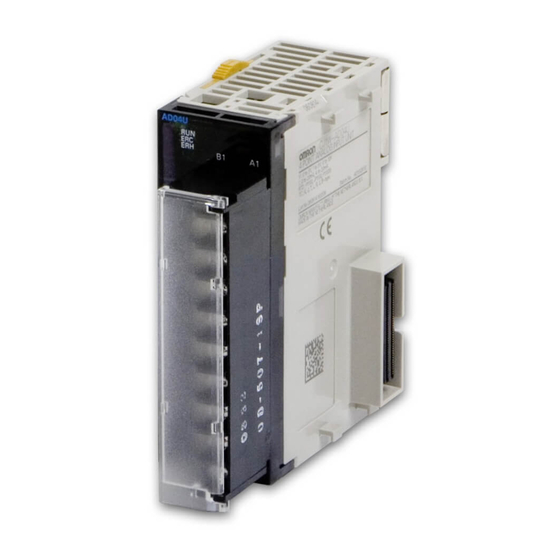
Section 2-3 Nomenclature and Functions Nomenclature and Functions Components CJ1W-AD04U CJ1W-AD04U-SL FRONT AD04U AD04U Indicators Terminal block MACH MACH Unit number setting switch DIN Track mounting pin CJ1W-AD04U CJ1W-AD04U-SL Slider Slider SIDE Expansion Expansion connector connector Slider Slider Terminal block lock lever (pull down to release terminal block) - Page 35 Section 2-3 Nomenclature and Functions Indicators The indicators show the operating status of the Unit. The following table shows the meanings of the indicators. Meaning Indicator Operating status RUN (green) Operating Operating normally. Not lit Unit has stopped exchanging data with the CPU Unit. ERC (red) Error detected by An alarm occurred (such as detection of a sensor error) or...
-
Page 36: Installation And Wiring
SECTION 3 Installation and Wiring This section explains how to install and wire the CJ1W-AD04U and CJ1W-AD04U-SL Universal Input Units. Installing the Units ..........Wiring . -
Page 37: Installing The Units
Section 3-1 Installing the Units Installing the Units Mount the Universal Input Unit in a CJ-series CPU Rack or Expansion Rack. CPU Rack Power Supply Unit CPU Unit Connected Units (10 max.) End Cover (included with CPU Unit) Use the following procedure to mount the Units. 1,2,3... -
Page 38: Wiring
Section 3-2 Wiring • When wiring a Unit, leave the protective label on the top of the Unit in place to prevent wire clippings or other materials from getting inside the Unit. When the wiring has been completed, the label must be removed to allow air to flow for cooling. - Page 39 Section 3-2 Wiring 4. Wire the same lengths to A, B, and b so that the impedance will be the same. In particular, do not short circuit between B and b at the terminal block. 5. Always ground the GR terminal on the Power Supply Unit of the PLC. 6.
- Page 40 Wiring Section 3-2 Wiring a Screwless Clamp Terminal Block (CJ1W-AD04U-SL) Terminal Block Arrangement Release button hole N.C. N.C. N.C. N.C. N.C. Wire hole N.C. Input 2 V+ Input 1 V+ Input 2 − Input 1− Input 2 I+ Input 1 I+ Input 4 V+ Input 3 V+ Input 4 −...
- Page 41 • Contact information for other companies Allen-Bradley: www.ab.com Phoenix Contact: www.phoenixcontact.com Weidmuller: www.weidmuller.com OMRON 24 Service (Japanese): www.omron24.co.jp Input Wiring Precautions Observe the following wiring precautions to optimize the Unit’s functions and reduce the effects of noise. • Use twisted-pair shielded wire for the input lines.
-
Page 42: Input Functions And Operating Procedures
SECTION 4 Input Functions and Operating Procedures This section describes the input functions and operating procedures of the CJ1W-AD04U and CJ1W-AD04U-SL Universal Input Unit. Exchanging Data with the CPU Unit ....... Detailed Description of User Settings Area Data . -
Page 43: Exchanging Data With The Cpu Unit
Exchanging Data with the CPU Unit Section 4-1 Exchanging Data with the CPU Unit Outline of Data Exchange Data is exchanged between the CPU Unit and the CJ1W-AD04U and CJ1W- AD04U-SL Universal Input Units via the Special I/O Unit Area (for data used to operate the Unit) and the Special I/O Unit words in the DM Area (for data used for settings). - Page 44 Section 4-1 Exchanging Data with the CPU Unit Contents of the Operating Data and Unit Settings Areas The following functions are assigned to data in the CPU Unit’s Special I/O Unit Area and Special I/O Unit words in the DM Area. Data area Function Timing of data...
- Page 45 Section 4-1 Exchanging Data with the CPU Unit Unit Number Settings The Special I/O Unit Area word addresses and the Special I/O Unit word addresses in the DM Area that each Universal Input Unit occupies are set by the unit number switch on the front panel of the Unit. Unit number setting switches Switch...
- Page 46 Exchanging Data with the CPU Unit Section 4-1 Bits Unit Number Bits Unit Number Bits Unit Number A505.00 Unit #48 A506.00 Unit #64 A507.00 Unit #80 A505.01 Unit #49 A506.01 Unit #65 A507.01 Unit #81 A505.02 Unit #50 A506.02 Unit #66 A507.02 Unit #82 A505.03...
- Page 47 Section 4-1 Exchanging Data with the CPU Unit Data Allocation in the User Settings Area DM Area The Unit’s various user settings are made in the Special I/O Unit words in the DM Area. Settings such as the alarm settings and span/zero adjustment val- ues can be changed while the CPU Unit is operating.
- Page 48 Section 4-1 Exchanging Data with the CPU Unit DM word (See note 1.) m + 10 Input 3 Process value H (high limit) alarm setting m + 11 Input 3 Process value L (low limit) alarm setting m + 12 Input 3 Span adjustment value m + 13 Input 3 Zero adjustment value...
- Page 49 Section 4-1 Exchanging Data with the CPU Unit Set Values and Stored Values Setting Set value or stored value Default Page Unit values read com- 12345 (3039 hex): Transfer initial values from the Input Unit to the P. 39 mand CPU Unit.
- Page 50 Section 4-1 Exchanging Data with the CPU Unit Data Allocation in the Operating Data Area The Unit’s Operating Data data is transferred to the CPU Unit every cycle through the 10 words allocated to the Unit in the Special I/O Unit Area. CJ1W-AD04U/AD04U-SL CJ-series CPU Unit Universal Input Unit...
- Page 51 Section 4-1 Exchanging Data with the CPU Unit Set Values and Stored Values Contents Set Values and Stored Values Page Process value alarm H (high limit) 0: Process value < Set value P. 37 1: Process value ≥ Set value L (low limit) 0: Process value >...
-
Page 52: Detailed Description Of User Settings Area Data
Section 4-2 Detailed Description of User Settings Area Data Example 2: In this example, the process values are read from multiple inputs. (The unit number is 0.) Input condition XFER(070) The process values in CIO 2001 to CIO 2004 #0004 (input numbers 1 to 4) are read to DM Area words D00001 to D00004. -
Page 53: Zero/Span Adjustment
Section 4-2 Detailed Description of User Settings Area Data 4-2-3 Zero/Span Adjustment The zero point and span point can be adjusted for a process value. The zero adjustment offsets the line plotting values before and after adjust- ment parallel to the original line. The span adjustment changes the slope of the line (i.e., the gain) around the minimum value in the range. -
Page 54: Scaling Function Settings
Section 4-2 Detailed Description of User Settings Area Data If the value is abnormal, change the zero adjustment value in the DM Area, and adjust the offset (parallel movement) value. DM word Function Set value Input 1 zero adjustment value −9,999 to −1 (D8F1 to FFFF hex) m + 5 0 to 9,999 (0000 to 270F hex) m + 9... -
Page 55: Sensor Error (Disconnection) Detection And Operation
Section 4-2 Detailed Description of User Settings Area Data 4-2-5 Sensor Error (Disconnection) Detection and Operation It is possible to detect a disconnected input circuit if the input type is set to thermocouple input, platinum resistance thermometer input, 1 to 5 V voltage input, or 4 to 20 mA current input. -
Page 56: 4-2-6 Process Value Alarm Settings
Section 4-2 Detailed Description of User Settings Area Data The high/low value setting is set in DM word m+18, as shown in the following diagram. 15 14 13 12 11 10 09 08 07 06 05 04 03 02 01 00 D (m + 18) 0: Fix the process value at highest value when there is a sensor error. -
Page 57: Alarm Hysteresis Settings
Section 4-2 Detailed Description of User Settings Area Data 4-2-7 Alarm Hysteresis Settings Hysteresis values can be set for the process value alarm outputs. Frequent ON/OFF switching of the alarm output can be eliminated by setting a dead zone between the alarm output’s start and stop. Alarm high limit (H) Alarm low limit (L) Process value input... -
Page 58: Cold Junction Sensor Error Detection
Section 4-3 Expansion Setting Area 4-2-9 Cold Junction Sensor Error Detection If one of the Unit’s built-in cold junction sensors fails, the error is output to the corresponding bit in CIO word n+9, as shown in the following table. CIO word Contents CIO n + 9 Input 1 cold junction sensor error... - Page 59 Section 4-3 Expansion Setting Area Set DM word m+39 to 1 (enabling the Expansion Setting Area) and set m+40 to the word address of an output device such as a CJ1W-OC201 Output Unit. The high and low limit alarm outputs for inputs 1 to 4 are written to CIO n (in the CPU Unit) every cycle, and simultaneously written to the word specified in m+40.
- Page 60 Expansion Setting Area Section 4-3 DM words m+39 and m+40 enable the Expansion Setting Area and set it to CIO 0005. Universal Input Unit CJ1 CPU Unit CJ1W-OC221 AD04U OC221 16 outputs Data areas CIO 0004 CIO 2000 CIO 0 CIO 2009 CIO 4 External alarm...
- Page 61 Expansion Setting Area Section 4-3...
-
Page 62: Error Processing
SECTION 5 Error Processing This section explains how to troubleshoot errors and alarms that occur in the CJ1W-AD04U and CJ1W-AD04U-SL Universal Input Units. Indicators and Error Flowchart ........Errors Detected by the Universal Input Unit. -
Page 63: Indicators And Error Flowchart
Indicators and Error Flowchart Section 5-1 Indicators and Error Flowchart Indicators If an alarm or error occurs in the Universal Input Unit, the ERC or ERH indica- tors on the front panel of the Unit will light. Front panel of Unit AD04U Indicator Meaning... - Page 64 Section 5-2 Errors Detected by the Universal Input Unit Processing and Results in the Continuously Refreshed Area Processing Result LED indicators on Unit Data range error address stored in DM Area While the power is ON, an The Unit will continue operat- ERC indicator is lit.
-
Page 65: Errors Related To The Cpu Unit
Section 5-3 Errors Related to the CPU Unit Errors Related to the CPU Unit Contents Probable Error type Detailed Input Unit Remedy cause cause status (red) (green) Error in data During normal I/O bus error A data trans- Converted data Turn OFF the exchange with operation, an... - Page 66 Restarting Special I/O Units Section 5-4 Bits Unit number Bits Unit number Bits Unit number A502.09 Unit #9 A503.09 Unit #25 A504.09 Unit #41 A502.10 Unit #10 A503.10 Unit #26 A504.10 Unit #42 A502.11 Unit #11 A503.11 Unit #27 A504.11 Unit #43 A502.12 Unit #12...
-
Page 67: Troubleshooting
Section 5-5 Troubleshooting Troubleshooting The following tables explain the probable causes of troubles that may occur, and the countermeasures for dealing with them. Conversion Data Does Not Change Probable cause Countermeasure Page The span adjustment value is set to 0. Set the span adjustment value to a value other than 0. P. -
Page 68: Dimensions
Appendix A Dimensions CJ1W-AD04U Terminal Block Dimensions 17.5 AD04U MACH 7.62 74.77 CJ1W- AD04U-SL AD04U MACH... - Page 69 Appendix A Dimensions...
-
Page 70: Supplementary Explanations Of Functions
Appendix B Supplementary Explanations of Functions The following supplements the explanation given in 1-1 Features and Functions . Changing Set Values during Output of Process Value Alarm H (High Limit) Alarms When the alarm set value is raised while the alarm output is ON, the alarm output will be turned OFF when the following condition is satisfied. - Page 71 Appendix B Supplementary Explanations of Functions Alarm Operation when Upper Limit Is Less Than Lower Limit When setting the process value’s alarm set values, the high and low limit values can be set freely, regardless of which value is larger. Example: H <...
- Page 72 Appendix B Supplementary Explanations of Functions Setting Process Value Scaling with Negative Gain With process value scaling in industrial units, a negative gain can be set by reversing the maximum and minimum values in the range. The following values can be set for an input signal of 4 to 20 mA: Maximum process value in range = 0, minimum process value in range = 4000.
- Page 73 Appendix B Supplementary Explanations of Functions Process value (stored data) 4200 (105%) 4000 (100%) When process value is greater than 3,000, output turns ON. 3000 (75%) Process value scaling with negative gain Input signal 0 (0%) −200 (−5%) 3.2 mA 4 mA 20 mA 20.8 mA...
-
Page 74: Data Coding Tables
Appendix C Data Coding Tables @@: Unit number Setting contents word D2@@00 D2@@00 D2@@01 D2@@02 D2@@03 D2@@04 D2@@05 D2@@06 D2@@07 D2@@08 D2@@09 D2@@10 D2@@11 D2@@12 D2@@13 D2@@14 D2@@15 D2@@16 D2@@17 D2@@18 D2@@19 D2@@20 D2@@21 D2@@22 D2@@23 D2@@24 D2@@25 D2@@26 D2@@27 D2@@28 D2@@29 D2@@30... - Page 75 Appendix C Data Coding Tables Setting contents word D2@@39 0 D2@@40...
-
Page 76: Revision History
Revision History A manual revision code appears as a suffix to the catalog number on the front cover of the manual. Cat. No. W466-E1-02 Revision code The following table outlines the changes made to the manual during each revision. Page numbers refer to the previous version.
Need help?
Do you have a question about the SYSMAC CJ1W-AD04U and is the answer not in the manual?
Questions and answers