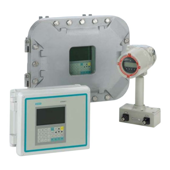
Siemens SITRANS FUG1010 IP65 NEMA 4X Instruction Manual
Ultrasonic flowmeters
Hide thumbs
Also See for SITRANS FUG1010 IP65 NEMA 4X:
- Operating instructions manual (271 pages) ,
- Quick start manual (194 pages)

Related Manuals for Siemens SITRANS FUG1010 IP65 NEMA 4X


Summary of Contents for Siemens SITRANS FUG1010 IP65 NEMA 4X
- Page 1 Ultrasonic flowmeters SITRANS FUG1010 IP65 NEMA 4X Instruction Manual - September 2008 SITRANS F...
- Page 3 Field Manual CQO:1010GCNFM-3 September 2007 For use with Operating System Software Version 3.01.05E or later Prepared By Date Reviewed By Date Copyright©2007 Siemens Energy & Automation, Inc. All Rights Reserved Made in the USA Printed September 2007...
- Page 4 Manual Changes NOTE: For the latest updates and revisions to this field manual go to: and check the Product Manual listing. http://support.automation.siemens.com/...
- Page 6 Errata 1010FMA-46 ERRATA Digital Pgen Function and Wiring Procedure Update NOTE: The following applies to System 1010GN, 1010GCN and 1010GCSN Gas Flowmeter instal- lation manuals. Replace the PGEN menu cell description and set up procedure in the Data Span/Set/Cal menu Span Data option list including any related menu graphics and text throughout the manual with the following: PGEN The [PGEN P/Unit Volume] menu cell entry controls a digital output pulse function and is available in...
- Page 7 Errata 1010FMA-46 PGEN Wiring Diagram The unit must be wired as shown below before assigning PGEN output pulses. 1010N-1 1010N-7K, -7K2 OR -7K3 MAIN BOARD I/O CONNECTION BOARD DPGEN_2-Ø2 TTL PGEN SIGNAL TB2-12 DPGEN_2-Ø2 TTL/CMOS TTL LOGIC TO END USER QUADRATURE PHASE EQUIPMENT TB2-4 GND...
- Page 8 Errata 1010FMA-46 FOR POSITIVE FLOW PG3 and PG4 LAGS PG1 and PG2 by 90º REFERENCE PG1 or PG2 QUADRATURE LAGS FOR POSITIVE FLOW PG3 or PG4 FOR NEGATIVE FLOW PG3 and PG4 LEADS PG1 and PG2 by 90º REFERENCE PG1 or PG2 QUADRATURE LEADS FOR NEGATIVE FLOW PG3 or PG4...
- Page 10 1010FMA-56 MANUAL ADDENDUM Operating System Software Version Update Manual Addendum September 2008 Copyright © 2008 Siemens Energy & Automation, Inc. All rights reserved Made in the USA...
- Page 12 1010FMA-56 Manual Addendum Operating System Software Version Update INTRODUCTION The following software operating system version update is for Version 3 flowmeters. Please refer to this addendum when using this technical manual with Version 3 operating system software and flowmeters that have been updated to Version 5. Operating System Software Changes 1.
- Page 13 1010FMA-56 Manual Addendum Version 3 Version 5 Vs Min m/s Vs Min M/S Channel/Path Setup Chan/Path Setup Vfmax GAL/MIN Vfmax Date Site Created: Site Created: Empty % Empty Analog Output Trim Analog Out Trim Pick flowtube size and type Select flowtube and start operation Empty Flowtube Set Empty Pipe Set...
- Page 14 1010FMA-56 Manual Addendum 3. Total Units Total units are similar to flow units. TOTALIZE UNITS For STD VOLUME disabled Version 3 Version 5 CU FT KCU FT MACF MCU FT MMACF KCU M E3 M3 MCU M E6 M3 TOTALIZE UNITS For STD VOLUME enabled Version 3 Version 5...
- Page 16 1010FMA-57 MANUAL ADDENDUM Digital P-Gen Applications Procedure Update Manual Addendum September 2008 Copyright © 2008 Siemens Energy & Automation, Inc. All rights reserved Made in the USA...
- Page 17 1010FMA-57 Manual Addendum Digital P-Gen Applications Procedure Update INTRODUCTION The following Digital P-Gen applications procedure is to be added to the Data Span/Set/Cal Menu section of the SITRANS liquid and gas flowmeter manuals listed below: Gas Flowmeter Manuals FUG1010 IP 65 (NEMA 4X) Clamp-On Gas Flowmeter manual (CQO:1010GCNFM-3) FUG1010 IP 65 (NEMA 7) Compact Clamp-On Gas Flowmeter manual (CQO:1010GCXFM-3) FUG1010 IP 65 (NEMA 7) Compact Insert Gas Flowmeter manual (CQO:1010GXFM-3)
- Page 18 1010FMA-57 Manual Addendum The example below demostrates how to calculate the AnCal flow rate based on the desired pulse output frequency and the entered PGEN (Pulses / Unit volume) setting: For PGEN setting = 53 Pulses /CU FT and a desired frequency = 1000 Hz 1.
- Page 19 1010FMA-58 MANUAL ADDENDUM Digital Damping Procedure Update For Gas & Liquid Flowmeters Manual Addendum September 2008 Copyright © 2008 Siemens Energy & Automation, Inc. All rights reserved Made in the USA...
- Page 21 1010FMA-58 Manual Addendum Digital Damping Procedure Update for Gas & Liquid Flowmeters INTRODUCTION The following Digital Damping procedure updates are for SITRANS F gas and liquid clamp-on flowmeters.Replace the Digital Damping Control: (Hot Key 1 and 2) procedure in the “Detection Modes” section (sub-paragraph: Command Modes) in the appropriate gas and liquid STIRANS F flowmeter manuals.
- Page 22 1010FMA-58 Manual Addendum To access the Digital Damping Control using the Test Facilities Graph Screen, proceed as follows: 1. To use the Test Facilities Graph Screen you must have a working site. 2. To activate the Test Facilities Graph Screen: In the main menu, scroll to the [Diagnostic Data] menu and select [Test Facilities].
- Page 23 1010FMA-58 Manual Addendum To INCREASE the Digital Damping: 1. Press the <1> key while viewing the Test Facilities Graph Screen as shown above. The damping control [MinDamp #] should appear on the command line at the lower left-hand corner of the screen.
- Page 24 1010FMA-58 Manual Addendum Liquid Clamp-on Flowmeter Manuals Replace the Digital Damping Control: (Hot Key 1 and 2) procedure in the “Detection Modes” section (sub-paragraph: Command Modes) in the following flowmeter manuals: FUS1010 IP 65 (NEMA 4X) Clamp-On Flowmeter manual (CQO:1010NFM-3) FUE1010 IP 65 (NEMA 4X) Clamp-On Flowmeter manual (CQO:1010ENFM-3) FUH1010 IP 65 (NEMA 4X) Clamp-On Flowmeter manual (CQO:1010DVNFM-3) FUH1010 IP 65 (NEMA 4X) Clamp-On Flowmeter manual (CQO:1010PVNFM-3)
- Page 25 1010FMA-58 Manual Addendum To access the Digital Damping Control using the Test Facilities Graph Screen, proceed as follows: 1. To use the Test Facilities Graph Screen you must have a working site. 2. To activate the Test Facilities Graph Screen: In the main menu, scroll to the [Diagnostic Data] menu and select [Test Facilities].
- Page 26 1010FMA-58 Manual Addendum To INCREASE the Digital Damping: 1. Press the <1> key while viewing the Test Facilities Graph Screen as shown above. The damping control [MinDamp #] should appear on the command line at the lower left-hand corner of the screen.
- Page 27 1010FMA-14 MANUAL ADDENDUM SYSTEM 1010 EXPANDED I/O OPTION (For Systems Equipped With 1010N-7 Modules) Manual Addendum May 2002 Copyright©2008 Siemens Energy & Automation, Inc. All Rights Reserved Made in the USA...
- Page 29 In addition, refer to Installation Drawings 1010N-2-7 and 1010N-7-7 in the field manual appendices for additional connection information and terminal block numerical designators. NOTE: All meters in the System 1010N and DN product family can accept the Expanded I/O Module Option except 4-Channel meters. Siemens Dual Path SITE1 Use this menu to...
- Page 30 Manual Addendum 1010FMA-14 1010N-2 I/O Module The conventional 1010N-2 I/O module provides the following: Two self-powered, isolated 4-20 mA current loops (signals Io1 and Io2) that are assignable and spannable by the user to many flowmeter variables such as flow, sonic velocity, signal strength, etc.
- Page 31 Manual Addendum 1010FMA-14 EXPANDED I/O MODULE OPTION PROGRAMMING The diagram below illustrates the Expanded I/O Module Option programming for a Single Channel meter with a 1010N-7 Expanded I/O Module. FLOW COMPUTER INTERNAL OUTPUT CONNECTIONS TERMINAL STRIP Pgen1 Aux Io1 Pgen2 Aux Io2 Aux Io3 Aux Io4...
-
Page 33: Table Of Contents
Table Of Contents 1010GCNFM-3C TABLE OF CONTENTS Sect./Page Section 1 Introduction ....................1-1 Important Safety Considerations ..............1-1 Flowmeter Installation Steps............... 1-1 Theory Of Operation ................... 1-2 1.3.1 Introduction ....................1-2 1.3.2 Flow Profile Compensation ................. 1-3 1.3.3 Standard Volume Compensation ..............1-3 1.3.4 Mass Flow Compensation And Molecular Weight ........ - Page 34 1010GCNFM-3C Table Of Contents 4.1.4 How To Enable/Disable Site Security ............4-4 4.1.5 How To Delete A Site Setup ................ 4-5 4.1.6 How To Save/Rename A Site Setup ............. 4-5 The Pipe Data Menu ..................4-6 Pipe Configuration .................. 4-7 Pipe Configuration Menu Structure ............
- Page 35 Table Of Contents 1010GCNFM-3C The Operation Adjust Menu ..............4-32 Operation Adjust Menu Structure ............4-33 4.5.1 Damping Control ..................4-33 4.5.2 Deadband Control ..................4-34 4.5.3 Memory/Fault Set ..................4-34 Memory Delay (sec)................4-34 The Flow/Total Units Menu ................ 4-35 Totalizer Controls .................
- Page 36 1010GCNFM-3C Table Of Contents Makeup Latch ..................4-46 4.7.3 Calibrate Flow Rate ..................4-47 Intrinsic ....................4-47 Kc Calibration ..................4-47 Kc Factor ..................... 4-48 Selecting Kc Factor ................4-48 Calibration Tables 1 through 3 .............. 4-48 The Stripchart Setup Menu ................ 4-49 The Stripchart Setup Menu Structure .............
- Page 37 Table Of Contents 1010GCNFM-3C Introduction to [HF] Menu Item ............. 4-66 Using The [HF] Menu Item ..............4-66 “Manual” Adjustment ..............4-67 “Automatic” Adjustment ..............4-68 4.11.6 The Test Facilities Menu ................4-69 Test Facilities Commands ..............4-69 4.11.7 Detection Modes ..................4-70 The Test Facilities Graph Screen ............
- Page 38 1010GCNFM-3C Table Of Contents Date ....................4-86 Time ....................4-87 4.12.8 RS-232 Setup ....................4-87 RS-232 Setup Menu Structure .............. 4-88 Baud Rate ................... 4-88 Parity ....................4-88 Data Bits ..................... 4-89 Line Feed .................... 4-89 Network ID ..................4-89 RTS Key Time ..................
- Page 39 Table Of Contents 1010GCNFM-3C Reference Tables ..................6-5 FUG1010GCN Reynolds Compensation Factor ........6-5 Terminology Chart ................. 6-6 The NEMA Dual Path Menu Chart ..............6-8 The Meter Menu ..................6-8 The Clamp-on Gas Menu ............... 6-8 The Meter Facilities Menu ..............6-11 APPENDICES Appendix A Couplant Installation Instructions...
-
Page 41: Introduction
Siemens cannot accept responsibility for any damage that may occur due to failure to observe any local safety rules. If this equipment is used for a hazardous application (high line pressure, hostile liquid characteristics, perilous atmosphere, etc.), the end-user must ensure that only properly trained person-... -
Page 42: Theory Of Operation
Section 1 1010GCNFM-3C THEORY OF OPERATION 1.3.1 INTRODUCTION The FUG1010GCN Clamp-on Gas meter relies on the same Digitally Coded MultiPulse transit-time tech- nology used in our patented 1010 line of liquid flowmeters. Two Wide-Beam ultrasonic transducers per measuring path, alternating as transmitter and receiver, are used to interrogate the gas flowing within the metering section. -
Page 43: Flow Profile Compensation
Section 1 1010GCNFM-3C 1.3.2 FLOW PROFILE COMPENSATION Although gas has a very low absolute viscosity, its kinematic viscosity can be greater than water. The FUG1010GCN flowmeter continually computes the kinematic viscosity (centistokes) by dividing the fixed viscosity entry (from gas parameters menu) by the computed gas density (see paragraph 1.3.3). The Reynolds number is then computed as follows: Rn = 645 * Pipe ID * V where viscosity = cS = cP/density... -
Page 45: Fug1010Gcn Flowmeter Installation Instructions
Section 2 1010GCNFM-3C FUG1010GCN FLOWMETER INSTALLATION INSTRUCTIONS This section outlines the basic steps required to initially prepare an FUG1010GCN gas flow display computer (FDC) for installation. Refer to the interconnection diagram in this section when performing the following procedures. FUG1010GCN FLOWMETER TYPES FUG1010GCN Single Channel and 1010GDCN Dual Channel System NEMA 4/IP65 The FUG1010GCN series flowmeters are available in Single, Dual and Four Path versions. -
Page 46: Graphic Display Settings
GRAPHIC DISPLAY SETTINGS Within 30 seconds of power-up the flowmeter main display will become active and a Siemens graphic will appear. The screen also identifies the software version of the unit as shown below. ver. 3.01.00... -
Page 47: Fug1010Gcn Interconnection Diagram
Section 2 1010GCNFM-3C TRANSDUCER CABLE CONNECTORS FUG1010GCN FLOWMETER POWER SWITCH INPUT POWER CONNECTOR J10 POWER IN UP CONNECTOR DOWN CONNECTOR INPUT MODULE Analog Outputs Digital Outputs Analog Inputs RS-232 I/O UPSTREAM TRANSDUCER DOWNSTREAM CABLE TRANSDUCER CABLE CHANNEL 1 (UP) CHANNEL 1 (DN) Flow Vector FUG1010GCN Interconnection Diagram... -
Page 49: Getting Started
Section 3 1010GCNFM-3C GETTING STARTED THE KEYPAD ENABLE SWITCH FUG1010GCN models with integral keypads provide a keypad enable/disable switch to prevent unau- thorized access to the Installation Menu. In addition, a password entry option is available (see paragraph 4.1 Channel Setup Menu). The keypad enable/disable switch is located inside the lockable enclosure right above the I/O wiring terminal. -
Page 50: Introduction To The Fug1010Gcn Menu Screens
Current Selected Measurement Site Name Identified Current Selected Channel Meter Type Menu Prompt Line (Reverse Video) Highlighted Data Siemens 2 Channel [1] SITE 1 Scroll List and select desired Model Install Path Highlighted Transducer Model 1011HG Hi Prec Menu Cell Data... -
Page 51: How To Use The Installation Menu
3.4.1 ACCESSING AND LEAVING THE MENU Upon first turning the meter on you see a Siemens graphic. This means that there is no active site setup currently stored in memory. Note that this screen identifies the software version of the meter on the upper right-hand corner of the display. -
Page 52: How To Enter Data
The first left-hand item, [Meter Type], is highlighted (white type on black). The next left-hand selection is [Meter Facilities]. Use the [Meter Facili- ties] menu to set global meter options and controls. Top menu screen for dual-path system Siemens Dual Path SITE 1 Select Meter Type Meter Type >... -
Page 53: Multiple Select Option Lists
1010GCNFM-3C Pressing the <Right Arrow> again accesses the option list. This expands the reverse video highlight to show the list contents. Note that a cursor (arrow) points to the top item on the list. Siemens Dual Path SITE 1 Choose desired Flow rate volume units Flow Volume Units >Cubic Feet... -
Page 54: Entering Numeric Data
Section 3 1010GCNFM-3C Siemens Dual Path Path 2 Select Datalogger Data Datalogger Mode +Site Id Datalogger Data +Date Log Time Interval +Time Datalogger Events Path Flow Display Datalogger Flow Average Flow Raw Flow +Total +Path Vs Datalogger Setup Entering Numeric Data When a menu cell requires a numeric answer, press the <Right Arrow>... -
Page 55: The Meter Type Menu
Section 3 1010GCNFM-3C Siemens Dual Path Channel 1 Right Arrow & Enter Creates a new Site Recall Site Setup Channel Enable Create/Name Site ?A„ „ „ „ „ Site Security Delete Site Setup No Sites Save/Rename Site Channel/Path Setup Use the <Right and Left Arrows> to move through the character positions. If you wish to use numbers in your string, you can type them directly from the keypad. -
Page 56: Creating A New Site Setup
[Meter Type] screen. Refer to the figure below. Note that on the left-hand column [Meter Type] is highlighted as are all the available meter types on the right-hand column. Press the <Right Arrow>. This places a cursor (Î) next to [Dual Path Flow]. Siemens Dual Path Select Meter Type Meter Type >... - Page 57 1. At the [Channel/Path Setup] menu cell, press the <Right Arrow> to access the [Channel/Path Setup] menu. Press the <Down Arrow> and move the highlight down to [Create/Name Site]. Siemens Dual Path Right Arrow & Enter Creates a new Site...
- Page 58 5. Scroll back up to letter [T]. Move the cursor to the fourth character position. Scroll down to letter [E]. Move the cursor to the fifth character position. Type [1] on the numeric keypad to complete the site name. Siemens Dual Path Right Arrow & Enter Creates a new Site...
-
Page 59: The Fug1010Gcn Installation Menu
Section 4 1010GCNFM-3C THE FUG1010GCN INSTALLATION MENU CAUTION: The FUG1010GCN flowmeter menu parameters may have been pre-set at the fac- tory. The following section is provided for user reference should it be needed. High- lighted paragraph headings within this section indicate those menu cells that should be used only if the site needs to be completely installed. -
Page 60: The Channel/Path Setup Menu
Dual Path, operating with Path 1 active. This shows that the site setup [XYZ] is the active site. Siemens Dual Path Scroll saved Site Setup list and Enter Recall Site Setup Channel Enable This cell shows that Create/Name Site site setup [XYZ] is... -
Page 61: How To Recall A Site Setup
Section 4 1010GCNFM-3C 4.1.1 HOW TO RECALL A SITE SETUP The [Recall Site] command allows you to reinstall the system at a former site. For an original installation, see Create/Name Site for instructions on how to create a new Site Setup. This menu cell provides a list of saved site names. -
Page 62: How To Create/Name A Site Setup
Therefore, it is essential that you never forget or misplace the password. The only way to deactivate Site Security without knowing the password is to return the unit to Siemens. However, the process the factory uses to remove site security will eliminate any existing site data as well. The flowme- ter will allow an <F4>... -
Page 63: How To Delete A Site Setup
Section 4 1010GCNFM-3C 2. Press the <Up or Down Arrows> to scroll the option list to [On], then press <ENT>. [Enter Code?] appears at the top of the display screen. 3. Use the numeric keys or the <Up or Down Arrows> to move the cursor to the first character position. 4. -
Page 64: The Pipe Data Menu
1010GCNFM-3C Section 4 To Save or Rename a Site Setup: 1. Press the <Right Arrow> to access the first character position. 2. Use the <Up/Down Arrows> to select a character, then press the <Right Arrow> to highlight to next character position. 3. -
Page 65: Pipe Configuration
Use this menu pipes. Use this menu cell to select a Pipe cell to edit the Class from one of the meter's presets. Siemens Dual Path pipe outer The [Manual Entry] selection (default) Select Pipe Class from Pipe Table diameter. -
Page 66: Pipe Configuration Menu Structure
To highlight the desired piping configuration press To register selection press The default pipe configuration (Fully Developed) wll cause the flowmeter to use the conventional Reynolds Compensation Table when compensating for liquid flow profile behavior. Siemens Dual Path Path 1 Disignate Pipe Shape Near Transducers... -
Page 67: Pipe Data Menu Structure
Section 4 1010GCNFM-3C THE PIPE DATA MENU STRUCTURE Ö Ö Pipe Data Select Path 1, 2, or 1 and 2 Ö Select Pipe Class Ú Manual Entry ASA Stainless Steel* ASA Carbon Steel ASA Plastic Ú Metric DN Steel Metric SGP Steel Cast Iron Table Ductile Iron Table Copper Tube Table... -
Page 68: How To Select A Pipe Class
1010GCNFM-3C Section 4 THE PIPE DATA MENU STRUCTURE (continued) Ö Ö Pipe Data (cont.) Pipe OD (in / mm) xx.xx (numeric entry). (Auto if specific pipe is selected) Ö Ö Pipe Material Steel Ú Aluminum Black Iron Brass Cast Iron CuNi (70/30) CuNi (90/10) Copper... -
Page 69: How To Select A Pipe Size
Section 4 1010GCNFM-3C 4.2.2 HOW TO SELECT A PIPE SIZE Selecting a Pipe Size installs the selected pipe parameters into the balance of the Pipe Data menu cells and prepares the 1010 for Transducer selection and Installation. This option is not applicable if the Pipe Class is [Manual Entry]. -
Page 70: Pipe Id (In)
1010GCNFM-3C Section 4 NOTE: Do not use ASA schedule code to specify the wall thickness. You must enter actual di- mensions. To enter the Pipe Wall Thickness: To enable numeric entry press Use the keypad’s numeric keys to type exact wall thickness (use in/mm). To register the pipe wall thickness press 4.2.6 PIPE ID (in. -
Page 71: Mod Of Elast Psi
Each item in the gas parameters menu can be edited by the user. Pressing the <Right Arrow> key on any of these menu items will enable numeric entry, allowing you to override the default values. Siemens 2 Channel SITE 1 Base Temp. -
Page 72: Gas Parameters Menu Structure And Defaults
1010GCNFM-3C Section 4 GAS PARAMETERS MENU STRUCTURE AND DEFAULTS Gas Parameters Base Temp F (15.5 Enter reference temperature in C or F. Base Pres. PSIA 14.7 psia (1.014 bara) Enter reference pressure in PSIA or BARA. Spec. Heat Ratio Enter gas specific heat ratio (constant pressure to con- stant volume.) Viscosity (cP) 0.010 centipoise... -
Page 73: Fixed Mw G/Mole
Section 4 1010GCNFM-3C The Reynolds number is computed as indicated: U ˜ id ˜ V Rn = 645 ˜ where: ρ = density at flowing conditions (g/cc) id = spool inside dia (in) = Flow velocity (ips) cP = absolute gas viscosity (centipoise) 4.3.4 FIXED MW g/mole The flow computer uses the measured gas temperature, sonic velocity and specific heat ratio to com- pute the average specific gravity of the gas being measure. -
Page 74: Z Base
Z-factor and Density values accordingly. If a gas composition was provided to Siemens with the purchase order, then the meter may already be configured for the specified gas composition and would be indicated in the documentation provided with each meter. -
Page 75: Aga8 Table Generation And Installation Instructions
Section 4 1010GCNFM-3C The table values for temperature must be arranged in ascending order and consist of exactly 10 points. The units of entry must be degrees Kelvin. The table values for Density and Z-factor must be entered for each combination of entered temperature and pressure (100 points for each). -
Page 76: Example #1
1010GCNFM-3C Section 4 Syntax for entry of the pressure and temperature index array is: cv pres_grid[i] pressure where i = 0 to 9 cv temp_grid[j] temp where j = 0 to 9 Syntax for entry of the density and Z factor values is: cv dens_grid[k] density where k = 0 to 99 cv z_grid[k] zfactor... -
Page 77: Example #2
Section 4 1010GCNFM-3C Z-factor vs. Pressure and Temperature 1000 1150 1300 1450 0.9825 0.9571 0.9318 0.9066 0.8817 0.8575 0.8341 0.8119 0.7913 0.7729 0.9842 0.9615 0.9389 0.9166 0.8947 0.8735 0.8531 0.8338 0.816 0.7999 0.9858 0.9654 0.9452 0.9254 0.9061 0.8874 0.8696 0.8528 0.8372 0.8232 0.9872... - Page 78 Once you select the type, use this menu cell to specify the transducer size. Use this menu cell to select the type of Siemens 2 Channel FLOW1 transducer to be installed. Scroll List and select desired Model Install Path...
-
Page 79: How To Select A Transducer Model
Section 4 1010GCNFM-3C PICK/INSTALL XDCR MENU STRUCTURE Ö Ö Pick/Install Xdcr Install Path Ú Ú Transducer Model 1011G Universal Ú Ú 1011HG Hi Precision Ö Transducer Size 1011G Universal 1011HG High Precision Ú Ú A1HA1H Ú Ú Ö Xdcr Mount Mode Direct Ú... -
Page 80: How To Select A Transducer Size
1010GCNFM-3C Section 4 To select a Transducer Type: To access the [Transducer Model] option list press To move the cursor to the required transducer model press To store your selection press 4.4.2 HOW TO SELECT A TRANSDUCER SIZE When you move the cursor to Transducer Size, the highlighted prompt at the top of the display screen shows a list of recommended transducer sizes. -
Page 81: Reviewing The Spacing Method
Section 4 1010GCNFM-3C 4.4.4 REVIEWING THE SPACING METHOD The flowmeter analyzes your transducer selection, mounting mode and pipe size to determine the best way to install your transducers. It will recommend the use of either a mounting track, a spacer bar, or independent mounting. -
Page 82: The Number Index Menu Cell
1010GCNFM-3C Section 4 4.4.6 THE NUMBER INDEX MENU CELL Selecting the Spacing Offset allows the flowmeter to calculate the Number Index. The Number Index establishes the spacing between a pair of transducers. You cannot override this recommendation. To complete the transducer installation, you must accept the Number Index by mounting the transducer at that point on your spacer bar or mounting track. - Page 83 To access the [Install Completed?] option list, press the <Right Arrow>. Press <Down Arrow> and scroll to the [Install] menu cell and then press <ENT> (unless other- wise directed to do so by the Technical Service Department). Siemens Dual Path SITE1...
-
Page 84: Force Transmit Procedure
To initiate the Force Transmit function, refer to the example shown below. 1. After [Install] is selected press <ENT>. While the flowmeter is going through the drives (see menu screen below), press the <ALT> and <MENU> keys simultaneously. Siemens Dual Path SITE1... -
Page 85: The Zero Flow Adjust Menu
Section 4 1010GCNFM-3C 3. To exit Force Transmit, press the <Left Arrow> and a Detection Fault prompt will appear (see above). Press the <Left Arrow> again and the flowmeter will return to the Pick/Install Xdcr menu and highlight the [Zero Flow Adjust] menu cell. 4. -
Page 86: Autozero
1010GCNFM-3C Section 4 To accept the Measured Vs: Press moves the cursor to the [Empty Pipe Set] menu cell. If you decide to edit the Measured Vs: To activate numeric entry press Use the numeric keys to type the new Vs value (in meters-per-second). To store the corrected Vs press The flow computer may recommend a new Number Index and prompt you to press Remount the transducer at the new Number Index. -
Page 87: Reversamatic
Section 4 1010GCNFM-3C ReversaMatic This routine involves swapping the Up and Down transducers on the pipe (while keeping the cables attached) such that the difference in the transit-time change represents the zero offset. The fixed zero offset value is stored in memory in the same manner as described in Actual Zero. This routine would generally be used whenever flow cannot be stopped and the transducers cannot be mounted in the Reflect Mode configuration. -
Page 88: Using Reversamatic
1010GCNFM-3C Section 4 Using ReversaMatic If site conditions do not permit stopping the flow rate at the mounting location, and Reflect Mount is not possible, then use the ReversaMatic routine to establish the zero flow level. To invoke ReversaMatic: To access the [Zero Flow Adjust] option list press Move the cursor to [ReversaMatic]. -
Page 89: Zeromatic (Optional Function)
To access the [Zero Flow Adjust] option list press NOTE: If ZeroMatic is not running, the [Actual Zero] menu item will be displayed next to the [Zero Flow Adjust] menu cell. Siemens Dual Path SITE1 Conforms Indicated flow to Actual Zero... -
Page 90: The Operation Adjust Menu
Section 4 When the inital makeup of ZeroMatic is complete the screen will return to the Pick/Install Xdcr menu and automatically highlight [Operation Adjust], which is the next menu cell. Siemens Dual Path SITE 1 Conforms operation to user Preferences... -
Page 91: Operation Adjust Menu Structure
Section 4 1010GCNFM-3C Use this menu cell to Use this menu cell to Siemens Dual Path SITE1 select either select meter response SmartSlew™ or Time Determine Fault Memory Delay to a fault condition. Average output Damping Control Smart Slew Fault drops outputs to damping. -
Page 92: Deadband Control
1010GCNFM-3C Section 4 4.5.2 DEADBAND CONTROL Use Deadband Control to instruct the meter to report zero flow if the flow rate falls below a specified level (usually a very low rate). It will prevent the possibility of data scatter (a natural result of digital computa- tion) from causing false totalizer accumulation during long non-flowing periods. -
Page 93: The Flow/Total Units Menu
Standard Volume either volumetric or mass flow Compensation of volumetric rate units . flow rate and total volume. Siemens 2 Channel [1] SITE1 Use this menu cell to select a Choose desired Flow rate volume units time base for the flow rate units. -
Page 94: The Flow/Total Units Menu Structure
1010GCNFM-3C Section 4 THE FLOW/TOTAL UNITS MENU STRUCTURE Ö Ú Flow/Total Units Ö Flow Volume Units Ö Volume Units Cubic Feet Cubic Meters Pounds Kilograms Ú Tons Metric Tons Ft/Sec (Vel) M/Sec (Vel) Std Vol Corr Ö Ú Ú Ö Ú... -
Page 95: Flow Time Units
Section 4 1010GCNFM-3C To enable or disable the Std Vol Corr:: 1. Press the <Right Arrow> to access the [Std Vol Corr] option list. 2. Use the <Up or Down Arrow> to move the cursor to the required selection (NO or YES). 3. -
Page 96: Totalizer Scale
1010GCNFM-3C Section 4 To change the default setting: 1. Press the <Right Arrow> to access the [Total Volume Units] option list. 2. Use the <Up or Down Arrow> to move the cursor to the desired Total volume units. 3. Press <ENT> to store selection. 4.6.7 TOTALIZER SCALE After you select totalizer units, the meter automatically computes a prefix to provide the best combina- tion of capacity and resolution (e.g., KCU FT/HR). -
Page 97: Totalizer Mode
Section 4 1010GCNFM-3C 4.6.9 TOTALIZER MODE The Totalizer function operates in any of the modes listed below: MODE FLOW DIRECTION NOTES POSFLOW positive flow Accumulates flow in positive direction only NEGFLOW negative flow Accumulates flow in reverse direction only NETFLOW positive or negative Adds to positive total;... -
Page 98: The Data Span/Set/Cal Menu Structure
1010GCNFM-3C Section 4 THE DATA SPAN/SET/CAL MENU STRUCTURE Ö Ö Data Span/Set/Cal Span Data Ú PGEN P/(Units)* xxxx.xxx (numeric entry) Max Flow (Units) x.xxx (numeric entry) Min Flow (Units) x.xxx (numeric entry) Max Flow2 (Units) x.xxx (numeric entry) Min Flow 2(Units) x.xxx (numeric entry) Max Vs m/s x.xxx (numeric entry) -
Page 99: Span Data
Ú Clear Pt. Ö Table Active 3 Ö Clear Table 3 Ú Siemens Dual Path SITE1 Use this menu to define Use this menu to set the Define data Alarm thresholds setpoints for the alarm low and high range for relay outputs. -
Page 100: Pgen
1010GCNFM-3C Section 4 (continued) Vs is the sonic velocity in meters-per-second (m/s) of the flowing gas. Spanned gas The min. and max. Vs entries establish the Vs span. Max Vs (m/s) defines sonic velocity: 100% of span. The Min Vs (m/s) defines 0% of span. Vsg is the inferred operating specific gravity of the gas. -
Page 101: Min Flow
Section 4 1010GCNFM-3C To enter the Max Flow range setting: 1. Press the <Right Arrow> to activate numeric entry. 2. Use the numeric keys to type the maximum flow rate (100% of range). 3. Press <ENT> to store the data. Min Flow The [Min Flow] menu cell stores the minimum range for the flow rate output (Vfo). -
Page 102: Max Base S.g
1010GCNFM-3C Section 4 Max Base S.G. The [Max Base S.G.] menu cell stores the maximum range value for the Specific Gravity of a gas at base temperature. The specific gravity (S.G.) will be displayed as the maximum on the Stripchart. Min Base S.G. -
Page 103: Low Flow
Section 4 1010GCNFM-3C Low Flow The [Low Flow] menu cell allows you to set the LO Alarm relay trip-point and the position of the LO Alarm cursor on the Stripchart Display. The entered value must fall within the volumetric flow (Vfo) analog span for the Low Alarm cursor to appear on the Graphic Screen. -
Page 104: Turbulence
1010GCNFM-3C Section 4 To enter an Interface Vs or SG alarm setpoint: 1. Press the <Right Arrow> to activate numeric entry. 2. Use the numeric keys to type the Interface value (meters/sec for Vs or SG). 3. Press <ENT> to store the data. Turbulence % The ability of FUG1010GCN to operate with substantial gas non-homogeneity (possibly caused by water vapor mixing) surpasses all other transit-time systems. -
Page 105: Calibrate Flowrate
The intrinsic calibration of the FUG1010GCN is excellent as confirmed by numerous laboratory and field trials under diverse application conditions. Siemens can confidently say that in any given application, the majority of conventional flowmeters can not match the system’s measurement range or its linearity. -
Page 106: Kc Factor
1010GCNFM-3C Section 4 Kc Factor To obtain the Kc factor, compare flow total data taken simultaneously from the FUG1010GCN and a reference meter whose accuracy meets the required standard. Allow both meters to accumulate flow total data long enough to average out any differences due to flow fluctuation between the two meter locations. -
Page 107: The Stripchart Setup Menu
Section 4 1010GCNFM-3C The table may contain up to 32 pairs of these slope correction factors. Note that the Kc factor, unlike these slope correction factors, is entered as a signed percent change in rate, while these factors are simply rate multipliers. As points are entered, the point editor will provide list access to the already entered points plus access to the [New Point] menu cell, used to add a new point. -
Page 108: Select Data
1010GCNFM-3C Section 4 Use this menu cell Siemens Dual Path FLOW1 to select a data item to display on Select Data Units or Percent Display the stripchart. Select Data Data Display Data Rate Units Time Base 1 second Stripchart Clear... -
Page 109: Stripchart Clear
Port to external printers or computers. Note that a single-channel meter uses a compression algorithm to maximize Datalogger storage. This disables back scrolling of datalogger reports. Use this menu cell to Siemens 2 Channel [2] Channel 2 pick a destination for Select datalogger destination Datalogger reports. -
Page 110: The Datalogger Setup Menu Structure
1010GCNFM-3C Section 4 To select a Datalogger Mode: 1. Press the <Right Arrow> to access the [Datalogger Mode] option list. 2. Press <Up or Down Arrow> to move the cursor to the desired mode. Press <ENT> to store the selection. THE DATALOGGER SETUP MENU STRUCTURE Ö... -
Page 111: Datalogger Data
Section 4 1010GCNFM-3C 4.9.2 DATALOGGER DATA You can set the Datalogger to record any or all of the data offered on the Datalogger Data option list. However, you should be aware that recording unneeded data wastes valuable system RAM. However, we recommend that you always select [Site ID] (name) and [Time] to identify each line of data. -
Page 112: Log Time Interval
1010GCNFM-3C Section 4 To deselect Datalogger Data: 1. Move the cursor to the data item then press <CLR>. Note that this removes the plus sign (+) from the item. 2. After selecting/deselecting all desired items, press the <Left Arrow> to leave the [Datalogger Data] option list. -
Page 113: The I/O Data Control Menu
Setup] assigns functions to the meter’s current, voltage and pulse rate outputs. Each menu cell presents an option list of the available data items. In addition, you can set up the alarm relays, enable and span the analog input ports. Siemens Dual Path TEST1... -
Page 114: The I/O Data Control Menu Structure
1010GCNFM-3C Section 4 THE I/O DATA CONTROL MENU STRUCTURE (Note: For Dual Path flowmeters: “1” = Path 1, “2” = Path 2 and “S” represents the system or average channel. These characters appear to the left of the option list parameter.) Ö... -
Page 115: Analog Output Setup
Section 4 1010GCNFM-3C 4.10.1 ANALOG OUTPUT SETUP FUG1010GCN provides current, voltage and pulse-rate analog outputs. [Analog Output Setup] allows you to assign data functions for these signals. The computer’s terminal strip contains the analog output terminals. System 1010 Analog Outputs Io (Isolated current) 4 to 20 mA varies in proportion to an assigned data function. -
Page 116: Assigning Vo Output Functions
1010GCNFM-3C Section 4 To assign a function for the current output: 1. From the [Analog Out Setup], press the <Right Arrow> twice to access the [Io] option list. 2. Press the <Up or Down Arrow> to move the cursor to the desired data function. 3. -
Page 117: Relay Setup
Section 4 1010GCNFM-3C 4.10.2 RELAY SETUP Use this menu to assign a function to channel relays. FUG1010GCN supports 2 types of relay outputs, Alarm Relay and Pulse Relay. Alarm Relay outputs operate in “fail-safe” mode. The relay(s) are energized under normal conditions - an alarm condition causes the relay(s) to de-energize until alarm clears. The Pulse Relay output supports totalizer and batch relay functions. -
Page 118: Analog Input Setup
1010GCNFM-3C Section 4 4.10.3 ANALOG INPUT SETUP The Analog Input Setup function assigns an active analog input to a measurement channel/path. The meter provides four DC current input ports for single channel or Dual Path units. The DC current input ranges from a zero level of 4 mA to a full scale of 20 mA. -
Page 119: Diagnostic Data Menu Structure
Section 4 1010GCNFM-3C 4.11 THE DIAGNOSTICS DATA MENU Some Diagnostic Data items require a successful transducer installation and meter initialization to become available. These will report [Chan Not Setup] until you complete the installation pro- cedure. The Diagnostics Data menu provides real-time application and setup data, plus test routines for the selected channel. -
Page 120: Main Diagnostics Screen
Site Setup information. In addition, the Test Facilities menu provides test/control functions to optimize operation, analyze application conditions and to recover system operation. As shown below, diagnostics provides five menus and two menu cells: Siemens Dual Path SITE1 Real-Time flow-related data... -
Page 121: Flow Data Menu Items
Section 4 1010GCNFM-3C FLOW DATA MENU ITEMS Flow This is a real-time (updated) flow rate display in current rate units (e.g., KCU FT). Flow Vel F/S Linear flow velocity in f/s and m/s depending on preferrred units. Total This is a real-time (updated) flow total display in current total units (e.g., KCU FT). -
Page 122: The Application Info Menu
2. Type the desired flow rate using current rate units (e.g., 65.00 KCU FT/HR). Note that the [Flow] menu cell now reflects the artificial rate. 3. Move the cursor away from the menu cell to turn AnCal off. Siemens Dual Path SITE1... -
Page 123: The Gas Data Menu
4.11.4 THE GAS DATA MENU This menu shows the current Reynolds number used by the meter to implement flow profile compensa- tion, as well as operating pressure and temperature and computed gas properties. Siemens Dual Path SITE1 Current Reynolds number TEMP 1 0.00 F... -
Page 124: Site Setup Menu Items
1010GCNFM-3C Section 4 SITE SETUP MENU ITEMS fx (drive) Current Transmit drive code selected during Initial Makeup. The drive code controls the sonic transmit signal. N (burst length) Transmit burst duration selected during Initial Makeup. To change N count press <Right Arrow>. -
Page 125: Manual" Adjustment
In the [Diagnostic Data] Menu, highlight [Path Select] and select the desired transducer path. Press <ENT> to select path. Press the <Down Arrow> and scroll to the [Site Setup Data] menu cell. Press the <Right Arrow> to select it. Siemens Dual Path 4SS10G Siemens... -
Page 126: Automatic" Adjustment
1010GCNFM-3C Section 4 The new correction value will appear next to the [HF] menu cell as shown below. Siemens Dual Path 4SS10G fx (drive) N (burst length) Ltn in 5.316 Vf max CU Vs max m/s Vs min m/s 1355.00... -
Page 127: The Test Facilities Menu
The Test Facilities menu provides commands for system analysis and recovery. The most useful for the end-user are Makeup and Graph. Using these routines under the supervision of our technical support staff will help us to provide technical analysis and solutions. Siemens Dual Path SITE1... -
Page 128: Detection Modes
1010GCNFM-3C Section 4 4.11.7 DETECTION MODES FUG1010GCN flowmeters Version 3 or higher are equipped with a Test Facilities Graph Screen. The following paragraphs explain how the Test Facilities Graph Screen is used for troubleshooting FUG1010GCN flowmeters. The Test Facilities Graph Screen NOTE: The following is intended for 1010 VFMT systems with Graphic Displays only. -
Page 129: Entering The Diagnostic Graph Screen
Section 4 1010GCNFM-3C Entering the Diagnostic Graph Screen Before you can view the Diagnostic Graph Screen the FUG1010GCN flow channel must first be properly installed and operating with any fault condition (refer to the appropriate field manual). To view the Graph Screen first enter the [Test Facilities] menu, which is a submenu of the main [Diagnos- tic Data] menu. -
Page 130: Command Modes
1010GCNFM-3C Section 4 Command Modes Although the FUG1010GCN signal processing algorithms are capable of accommodating a very wide range of signal conditions, it may be desirable to override these default settings under extremely difficult operating conditions. The following functions are available for this purpose: Digital Damping Control: (Hot Key 1 and 2) The FUG1010GCN permits user modification of the digital averaging used by the signal processing routines. -
Page 131: Envelope Threshold Adjustment (Hot Key 5)
Section 4 1010GCNFM-3C ure the transit-time delta. This crossover will generally be close to the peak of the receive signal with at least one well formed (non-aberrated) receive cycle on each side of the crossover. If it appears that the placement of this crossover is unsatisfactory then it can be adjusted by pressing the <4>... -
Page 132: Description Of Graph Screen Text Display Parameters
1010GCNFM-3C Section 4 DESCRIPTION OF GRAPH SCREEN TEXT DISPLAY PARAMETERS Screen Text Parameters Menu List item Description Flow Measured flow rate in selected flow units. Vs (m/s) Sound Velocity in meters per second. Display Metrics Represents the digital sample position of the receive window. Correlated Plot Displays the receive waveform in its proper superposition or registra- tion. -
Page 133: Flow Computer Messages
Section 4 1010GCNFM-3C ally. If a problem seems unsolvable, call our Technical Service Department or your local Siemens Repre- sentative for expert help. Flow Computer Messages Certain actions or conditions invoke messages that may appear as a pop-up window, in the right-hand column of a given menu cell, or the highlighted prompt line at the top of the display screen. - Page 134 1010GCNFM-3C Section 4 The chart below shows the sequence of the [F4] routine: [Power On/Off + F4] [Clr Active Memory?] [Clr Saved Data?] Procedure to clear Active memory only: 1. Turn off power (if it is currently on). 2. Press the <F4> key and keep it pressed while you turn on power. The prompt: [Clr Active Memory? No] appears at the top of the screen.
-
Page 135: The Meter Facilities Menu And Graphic Display Screen
Verify/Adjust the analog pulse output using a frequency counter. Calibrate the RTD temperature sensors. Set the system clock/calendar. Obtain detailed software/hardware identification. This menu allows you to Siemens Dual Path SITE 1 specify default Select Default Units for all Menus measurement units. -
Page 136: The Table Setups Menu
1010GCNFM-3C Section 4 4.12.2 THE TABLE SETUPS MENU The [Table Setups] menu allows you to pre-condition your pipe table and transducer types. The edits made in [Table Setups] become the default settings for creating a new site. Transducers “marked” in the [Transducer Types] menu will be preferentially selected when the meter recommends transducers dur- ing the automatic Pick/Install Transducer routine. -
Page 137: Create/Edit Pipe
Section 4 1010GCNFM-3C PIPE TABLE MENU STRUCTURE (continued) Ö Create//Pipe Edit Choose Pipe Name Ö 200-DN 12CS_STD 12P_STD Ú Ú Ú 250-DN 12CS_XS 12P_XS 300-DN 16CS_STD 16P_STD 350-DN 16CS_XS 16P_XS 400-DN 18CS_STD 18P_STD 600-DN 18CS_XS 18P_XS Ö Metric SGP Steel 20CS_STD 20P_STD 20A-SGP... -
Page 138: Delete Pipe
1010GCNFM-3C Section 4 The highlight moves to Outer Diameter. Press to enable numeric entry. Type the actual pipe OD using the appropriate English or metric units. Press to store the OD. The highlight moves to Wall Thickness. Press to enable numeric entry. Type the actual wall thickness using the appropriate English or metric units. -
Page 139: The Datalogger Control Menu
Section 4 1010GCNFM-3C 4.12.3 THE DATALOGGER CONTROL MENU The Datalogger Setup menu in the Channel/Path Setup menu provides the Datalogger controls for the meter’s measurement channels. It allows you to enable usage, select data items/alarm events, a log- ging interval and a destination for your Datalogger reports. While the Datalogger Setup menu is mea- surement channel specific, this Datalogger Control menu provides global control functions. -
Page 140: Output Datalogger
1010GCNFM-3C Section 4 2. Use the <Up or Down Arrows> to scroll cursor to either [Line Wrap] or [No Line Wrap]. 3. Press <ENT> to view Datalogger contents. 4. Press <MENU> key to return to [Datalogger Control]. Output Datalogger This menu cell allows you to send the Datalogger contents to an external device (usually a computer or printer) via the meter’s RS-232 Serial I/O port. -
Page 141: Est Log Time Left
Section 4 1010GCNFM-3C All active channels in the Channel Setup menu must be disabled. To disable active channels, select the [Channel Enable] menu cell and then [No]. In the Datalogger Control menu, select [Circular Memory]. Press to access the [Circular Memory] option list. Move the cursor to [Yes] by pressing To store selection press Lastly, re-enable the channels that you disabled earlier to begin logging. -
Page 142: The Analog Output Trim Menu
1010GCNFM-3C Section 4 Defragment: Selecting [YES] for this item consolidates memory data blocks into contiguous storage; collapsing the filler regions. You may be able to use an additional block for site or datalogger storage as a result. Use this command if you seem to be out of memory even though the [Data Memory Left] item indicates free capacity. -
Page 143: Pgen Output Trim (Pgen 1 & Pgen 2)
The RTD Calibrate Menu appears on all Sitrans 1010N models. Use this menu to calibrate the 991T or 1011TN RTD Temperature Sensors to an external standard. It is important to note that Siemens RTD temperature sensors are factory-calibrated for high accuracy. We recommend that before deciding to perform the calibration, check the current RTD reading in [Diagnostics/Gas Data]. -
Page 144: Rtd Calibration By Data Entry
(time entry) Notice: All Siemens flowmeters include a real-time clock to provide a convenient date/time stamp for display screens and datalogger reports. The operating system does not rely on the date and time-of-day for any flowmeter operation. Therefore, the “Turn Of The Century” will have no effect on the proper functioning of any of our systems. -
Page 145: Time
NOTE: The RS-232 stop bit implementation is fixed. If you are using a communication program, such as Windows 3.xx Terminal or Windows 95/98/NT/2000/XP HyperTerminal, that in- cludes a field for stop bits, select 1 stop bit. Siemens Dual Path SITE 1... -
Page 146: Setup Menu Structure
1010GCNFM-3C Section 4 RS-232 SETUP MENU STRUCTURE Ö Ö RS-232 Setup Baud Rate Ú 1200 Ú 2400 4800 9600 38400 Ú Ö Ö Parity None Ú Space Even Mark Ú Ö Ö Data Bits Ú Ú Ö Ö Line Feed Ú... -
Page 147: Data Bits
Section 4 1010GCNFM-3C To edit the Parity setting: 1. Press the <Right Arrow> to access the [Parity] option list. 2. Move the cursor to the required parity setting. 3. Press <ENT> to store the data. This moves the cursor to [Data Bits]. Data Bits You can specify how many data bits the meter uses to format data words for serial transmissions. -
Page 148: Rts Key Time
1010GCNFM-3C Section 4 2. Use the numeric keys to type the Network ID number. 3. Press <ENT> to store Network ID. This moves the cursor to [RTS Key Time]. RTS Key Time During a serial transmission session, you can select how long the flow computer holds its request-to- send line high until it receives a clear-to-send signal. - Page 149 Total Units menu cells for clarification in these cases. Measured Sonic Signal Strength Velocity (in m/s) Site Name Selected (SITE #1) Measurement Path Percent of Turbulence Meter Type Detected Siemens SITE #1 Controlotron Dual Path [2] Totalizer Digital TURB FLOW CU FT/MIN Mode Average (TOTAL) Volumetric 80.1...
- Page 150 1010GCNFM-3C Section 4 Selected Measurement Site Setup Name Path Meter Type Percent of Span Controlotron Siemens SITE #1 Dual Path Bargraph Flow Display 200.0 FLOW CU FT/MIN Total 80.2 (Volumetric Average Flow Output) TOTAL KCU FT 18.20 80.20 Measured Instantaneous...
-
Page 151: Hardware Installation Guide
Section 5 1010GCNFM-3C HARDWARE INSTALLATION GUIDE PREPARING TO MOUNT THE TRANSDUCERS Installing the transducers is fairly straightforward. However, careful planning will avoid any snags that may delay the installation. Previously, based on the input you fed into the meter’s computer, it had recommended the transducers size, mounting option and spacing. -
Page 152: Selecting A Location For Clamp-On Transducers
Do not mount transducers from different ultrasonic flowmeters on the same pipe. Also, do not run the transducer cables in common bundles with cables from communication equipment, other Siemens systems, or any type of ultrasonic equipment. You can run these cables through a common conduit ONLY if they originate at the same flowmeter. -
Page 153: Preparing The Pipe
Section 5 1010GCNFM-3C We recommend Reflect mount whenever possible. This is the simplest way to mount the transducers. Also, Reflect mount resists abnormal flow profile conditions such as cross-flow within the flow stream. Reflect mode supports the AutoZero function, which zeroes the meter automatically without user-partici- pation. -
Page 154: Reflect Mode-Mounting Frames And Spacer Bar
Section 5 1010GCNFM-3C REFLECT MODE - MOUNTING FRAMES AND SPACER BAR The combination of a spacer bar with mounting frames is the easiest way to mount in Reflect Mode. The result is a rigid structure that eliminates spacing measurements, and maintains the transducer-to-trans- ducer geometry. - Page 155 Section 5 1010GCNFM-3C 2. On a flat surface, attach the spacer bar to a mounting frame so that the reference hole on the spacer bar fits over the post on the platform of the frame; tighten the securing screw. Slide the second mounting frame onto the other end of the spacer bar, align the number index hole with the post on the platform;...
-
Page 156: Direct Mode-Mounting Frames, Spacer Bar & Spacing Guides
Section 5 1010GCNFM-3C DIRECT MODE - MOUNTING FRAMES, SPACER BAR AND SPACING GUIDES The combination of mounting frames, spacer bar and spacing guides is the recommended way to mount Direct Mode transducers. The mounting frame establishes the axial alignment of the transducers, and allows you to remove and replace either transducer while preserving their exact mounting location. - Page 157 Section 5 1010GCNFM-3C MYLAR SPACING GUIDE 1. Perform all the required menu steps up until the point where the flowmeter issues the number index and prompts you to press to finish the transducer install routine. Make a note of the number index displayed in the Pick/Install menu. Check to ensure that you have a matched set of transducers.
- Page 158 Section 5 1010GCNFM-3C the bottom of the frame (see A below). While holding, also mark along the front edge of the frame with pencil or fine chalk line (see B below). Pipe Transducer Transducer Pipe Transducer Transducer Transducer Edge Line Spacer Bar Spacer Bar Transducer...
- Page 159 Section 5 1010GCNFM-3C SPACING GUIDE Mark (or fold) exactly Overlap Edge at half-way point CIRCUMFERENCE FINDING THE HALFWAY DISTANCE 11. Reinstall the spacing guide; its left edge abutting the transducers edge mark on the pipe and the overlapping edge in line with the dot (now a line) on the pipe (see “C” on previous page). Tape it in this position on the pipe.
-
Page 160: Using 1012T Mounting Tracks
Section 5 1010GCNFM-3C 17. Return to the menu, and press to finish the transducer install routine. USING 1012T MOUNTING TRACKS The 1012TP and 1012THP Mounting Tracks provide a rigid mounting platform for Series 1011 universal or high precision size A or B transducers. The mounting tracks service pipe sizes up to a maximum of 5.00”... - Page 161 Section 5 1010GCNFM-3C Transducer Transducer Chain Tension Chain Tension Upstream Upstream Clamping Screw Downstream Clamping Screw Downstream Xdcr Screw Screw Transducer Transducer Transducer Flow Î FlowÎ Î Î Î Reference Pin Reference Pin Shown Inserted Shown Inserted Track Rail Roller Track Rail Roller Number Index Pin...
-
Page 162: Installing A 1012T Mounting Track In Direct Mode
Section 5 1010GCNFM-3C 5. Once transducer is in place, secure with the transducer clamping screw. Do not overtighten. Observe the upstream/downstream orientation and connect the transducer cable to the computer’s input jack. If a dual-channel unit, make sure you connect the cable to the input jacks of the correct channel. Repeat this procedure for the number index transducer. - Page 163 Section 5 1010GCNFM-3C Tension Screw Tension Screw Center of this link is over the Center of this link is over the Hook Hook locating stud. an equal number of locating stud. An equal number of links on either side of this stud links on either side of this stud ensures 180 degrees opposed ensures 180 q opposed installation.
- Page 164 Notice: Siemens holds US Patent Number 4,929,368 on the CC#122 Coupling Compound and all compounds of this type. Its use is restricted to Siemens products only, unless a special license has been obtained. Licenses for use with other products are available through the Siemens Sales Department.
-
Page 165: Fug1010Gcn Application Notes
The meter’s computer provides comprehensive diagnostics data. Using this data, our engineers can analyze the system in relation to the application. Proper analysis will provide solutions to virtually any application problem. For technical assistance, please contact your local Siemens representative for expert help (www.siemens.com). -
Page 166: Repeatability
Section 6 1010GCNFM-3C 6.2.2 REPEATABILITY Some applications emphasize repeatability rather than absolute accuracy. FUG1010GCN features ex- cellent repeatability specifications since its digital “no moving parts” design avoids the adverse effects of hysteresis and other wear mechanisms typical of mechanical devices. 6.2.3 DATA STABILITY Two main factors influence the system’s data stability: Data Scatter and Drift Data Scatter... -
Page 167: Flow Data Scatter And Damping
1010GCNFM-3C Section 6 6.3.2 FLOW DATA SCATTER AND DAMPING The transit-time flowmeter’s ability to respond to the extremely fast flow fluctuations that characterize “real” flow may surprise you. Most conventional flowmeters cannot detect these rapid flow fluctuations since they are subject to unavoidable mechanical inertia. FUG1010GCN’s response speed is ideal for tracking fast flow transients. -
Page 168: Two-Phase Fluids
Section 6 1010GCNFM-3C Therefore, it measures and reports the aeration level as the analog output, Vtrb %. This represents the relative degree of turbulence detected within the flow stream. The flowmeter reports the Vtrb level until it impedes operation and forces a Fault Alarm. The Vtrb output accommodates applications requiring an aeration indicator. -
Page 169: Reference Tables
1010GCNFM-3C Section 6 REFERENCE TABLES The following tables provide reference data that may be required during site setup. FUG1010GCN REYNOLDS COMPENSATION FACTOR Reynolds # Positive Comp Negative Comp 0.7808 0.7808 1277 0.7869 0.7869 1566 0.7930 0.7930 1694 0.7991 0.7991 1830 0.8052 0.8052 1930... -
Page 170: Terminology Chart
Section 6 1010GCNFM-3C TERMINOLOGY CHART This chart provides explanations for uncommon terms used in this manual. TERM EXPLANATION Active Memory Section of RAM allocated for active site parameters (all current values). The flow computer receives site-specific operating instructions from Active Memory. Alphanumeric Field An 8-character data entry field that allows you to specify a Site Name or a Security code. - Page 171 1010GCNFM-3C Section 6 TERM EXPLANATION Local Display Refers to the FUG1010GCN integral display screen. Menu Sub-sections of the Installation Menu that you to define specific operational functions (e.g., RS-232 Setup). Menu Cell A location within a Menu where you define either a single numeric value or option list selection that supports the Sub-Menu’s function.
-
Page 172: The Nema Dual Path Menu Chart
Section 6 1010GCNFM-3C THE NEMA DUAL PATH MENU CHART This section shows the FUG1010GCN Permanent Dual Path Menu Chart. THE METER MENU Ö Meter Type Ö Dual Path Flow Channel/Path Setup THE CLAMP-ON GAS MENU Ö Ö Clamp-on Gas Channel/Path Setup Recall Site Setup Ú... - Page 173 1010GCNFM-3C Section 6 CLAMP-ON GAS MENU (continued) Clamp-on Gas Ö Flow/Total Units Ö Total Resolution Ú Totalizer Mode Ú Batch/Sample Total Data Span/Set/Cal Ö Span Data Ö Ú Pgen (Custody Transfer meters only) Max Flow /Max Flow2 Min Flow / Min Flow2 Max Vs m/s Min Vs m/s Max S.G.
- Page 174 Section 6 1010GCNFM-3C CLAMP-ON GAS MENU (continued) Ö Ö Clamp-on Gas Analog Output Setup Pgen 1/2 (not in Custody Transfer meters) Ö Ö Ö I/O Data Control Relay Setup Relay 1/2 Ú Ú Relay 3/4 Ö Ö Ö Analog Input Setup Iin1 - Iin4 Off/Input Ú...
-
Page 175: The Meter Facilities Menu
1010GCNFM-3C Section 6 THE METER FACILITIES MENU Ö Ö Meter Facilities Preferred Units English Ú Ú Metric Ö Ö Ö Table Setups Pipe Table Create/Edit Pipe Choose Pipe Class Ú Choose Pipe Name Outer Diameter (in) Ú Wall Thickness Ú Ú... - Page 176 APPENDIX A Couplant Installation Instructions Copyright©2008 Siemens Energy & Automation, Inc. All Rights Reserved Made in the USA...
- Page 178 CC129A-7 CC129A Dry Film Couplant/Damping Material Installation Instructions Installation Instructions CC129A-7 Revision D CN4973 February 2005 Copyright©2008 Siemens Energy & Automation, Inc. All Rights Reserved Made in the USA...
- Page 180 Do not mount transducers from different ultrasonic flowmeters on the same pipe. Also, do not run the transducer cables in common bundles with cables from communication equipment, other Siemens systems or any type of ultrasonic equipment. You can run these cables through a common conduit ONLY if they originate at the same flowmeter.
- Page 181 Installation Instructions CC129A-7 PREPARING THE PIPE SURFACE Pick a mounting location with the longest straight run. You must have easy access to at least one side of your pipe. For uninterrupted operation the mounting location must remain fully pres- surized, even at zero flow. Decide on your mounting mode (direct or reflect).
- Page 182 Installation Instructions CC129A-7 Table 1. CC129 Damping Material Thickness for 1010 Clamp-On Gas Systems Transducer CC129-1A Required Final Thickness Final Thickness Size Kit P/N Layers (in) (mm) CC129-1A-1 0.027 0.69 CC129-1A-1 0.027 0.69 CC129-1A-1 0.027 0.69 CC129-1A-1 0.027 0.69 CC129-1A-1 0.027 0.69 CC129-1A-2...
- Page 183 Installation Instructions CC129A-7 After determining the best sheet cutting pattern from suggestions above, mark the pipe for the starting edge of the dry couplant sheet position. Partially peel the sheet backing 1 to 2 inches from the starting edge, then carefully locate and press against the pipe surface.
- Page 184 Installation Instructions CC129A-7 MOUNTING ASSEMBLIES AND STRAPS ARE INSTALLED AFTER THE CC129-1A FILM IF FILM IS APPLIED IN PIECES, SEAM MAY BE BETWEEN, BUT NOT UNDER TRANSDUCERS CC129-1A FILM CUSTOMER'S PIPE AT LEAST 4" BOTH SIDES AT LEAST 2" BOTH ENDS 3.1.4 MOUNTING TRANSDUCERS Install the mounting assemblies and transducers directly on top of the CC129-1A material.
- Page 185 Installation Instructions CC129A-7 3.1.6 MULTI-BEAM INSTALLATIONS MIN 8” WIDE CC129A FILM 2-BEAM 4-BEAM WRAP CC129A ALL AROUND PIPE SMALL PIPES NOTE: Contact Siemens (www.siemens.com) for additional recommendations on use of CC129A Dry Film Couplant/Damping Compound. CN4973 February 2005...
- Page 186 Installation Instructions CC129A-7 GRACE ICE AND WATER SHIELD DAMPING MATERIAL An alternate (lower cost) pipe damping material referred to as "Grace Ice and Water Shield" can be considered for use with 1010 Clamp-On Gas systems. This opaque material has a black tar like appearance with a very tenacious adhesive backing.
- Page 188 APPENDIX B SITE SETUP CONSIDERATIONS FOR SITRANS F 1010/1020N BLIND SYSTEMS Siemens offers an economical “blind” 1010/1020 NEMA system (without a local keypad and graphic display screen). This supplement describes the hardware and software requirements for programming these models. Site setup for a blind unit requires a PC connected to the RS-232 serial port. These models include a serial interface cable for this purpose.
- Page 189 You can determine which cable is required for the your model flowmeter from the table below. Be sure you have the appropriate cable available for use. Meter Type Cable Type Siemens Part Number Notes Weatherproof Portable DB-9F – Amphenol...
- Page 190 Appendix 1010GCNFM-3C Signal PC DB-9 1010P/1020N 1010WP 1010N 1010X Name Terminal Terminal Terminal Terminal Terminal Ground Pin 5 Pin 5 Pin E TB1- pin 6 TB2-pin 16 Pin 2 Pin 3 Pin C TB1- pin 1 TB2-pin 11 Pin 3 Pin 2 Pin B TB1- pin 4...
- Page 191 1010GCNFM-3C Appendix None 6. You will now see a blank terminal screen. Next left-click [File] on the top menu bar. Drag the highlight down to [Properties] and then left-click. 7. Left-click the [Settings] tab. Expand the [Emulation] box by left-clicking the <Down Arrow> on the right-hand side.
- Page 192 Appendix 1010GCNFM-3C 9. You are now ready to communicate with the 1010 flowmeter. But first, save your settings by moving the mouse cursor to [File], sliding the cursor to [Save], then clicking [OK] on the Save dialog box. 10. The next time you want to use HyperTerminal: Click on Start.
- Page 193 1010GCNFM-3C Appendix Siemens Site Select Meter Type Meter Type Single Channel Meter Facilities NOTE: To facilitate connecting through modems, the [Menu] command times out after three minutes of inactivity. To maintain a longer connection type: Menu 1000 and press <ENT>.
- Page 194 Appendix 1010GCNFM-3C Navigating Through the Installation Menu After accessing the Installation Menu, you can begin to setup your flowmeter according to the instruc- tions in this manual. The chart below shows the PC keyboard equivalents to the 1010 keypad keys while you are in the menu.
- Page 195 1010GCNFM-3C Appendix Transfer of Information from a SITRANS F 1010/1020 Flowmeter to the PC With HyperTerminal active: 1. Point to Transfers, and click. 2. Select Capture Text. 3. Select desired drive path or directory, enter a file name, and click the Start button. 4.
- Page 196 Appendix 1010GCNFM-3C RESET PROCEDURE FOR BLIND SYSTEMS SITRANS F 1010 Blind systems allow you to perform a system reset via the RS-232 interface. The follow- ing instructions require the flowmeter to be connected serially to a PC. NOTE: Custom RS-232 settings for baud rate, parity and data bits may not be preserved. There- fore, be prepared to set your communications program back to the default (9600, Odd, 7) settings.
- Page 198 1010GCNFM-3C Appendix APPENDIX C ENGINEERING DRAWINGS Flow Computer Drawings 1010N-7 Installation Drawing, 1010 Series Single Channel Flow Computer 1010N-8 Outline Dimensions, 1010 Series Single Channel Flow Computer 1010DN-7 Installation Drawing, 1010 Series Dual Channel Flow Computer 1010DN-8 Outline Dimensions, 1010 Series Dual Channel Flow Computer 1010N-5-7 Installation Drawing, Analog Input Module 1010N-5D-7...
- Page 200 1010N - 7 21614...
- Page 201 MOUNTING HOLE PATTERN 7 8 9 4 5 6 1 2 3 OUTLINE DIMENSIONS 1010N - 8 21614...
- Page 202 1010DN - 7 21614...
- Page 203 MOUNTING HOLE PATTERN 7 8 9 4 5 6 1 2 3 1010DN - 8 21614...
- Page 204 INSTALLATION DRAWING ANALOG INPUT MODULE 1010N - 5 - 7 21614...
- Page 205 INSTALLATION DRAWING ANALOG INPUT MODULE 1010N - 5D - 7...
- Page 206 INSTALLATION WIRING I/O MODULE 1010N-2-7 21614...
- Page 207 TERMINAL BLOCK WIRING CONNECTIONS INSTALLATION DRAWING I/O MODULE 1010N - 2 - 7 21614...
- Page 212 +1)6 21614...
- Page 213 +1)6 C 21614...
- Page 214 75$16'8&(5 6,=( $ 75$16'8&(5 6,=( & 75$16'8&(5 6,=( & 75$16'8&(5 6,=( $ 75$16'8&(5 6,=( $ 75$16'8&(5 6,=( & +1)6 C 21614...
- Page 216 REFLECT MODE OPERATION PREFERRED MOUNTING PLANE SECURING MOUNTING FRAMES TO THE PIPE SURFACE USING THE SPACER BAR TO SET TRANSDUCER MOUNTING FRAME SPACING 1011NFPS - 7 21614...
- Page 217 PREFERRED MOUNTING PLANE DIRECT MODE OPERATION USING THE SPACER BAR TO SET TRANSDUCER MOUNTING FRAME SPACING SECURING MOUNTING FRAMES TO THE PIPE SURFACE 1011NFPS - 7 21614...
- Page 218 INSTALLING TRANSDUCERS IN MOUNTING FRAMES MATING 1012CNF SERIES TRANSDUCER CABLES WITH 1011NFPS SERIES TRANSDUCERS USE OF FLEXIBLE CONDUIT WITH TRANSDUCERS 1011NFPS - 7 21614...
- Page 219 REFLECT MODE OPERATION DIRECT MODE OPERATION AUXILIARY VIEW 1011NFPS - 7 C 21614...
- Page 220 1)36 21614...
- Page 221 1012BN-1 " L" " L" SPACER BAR USED WITH TRANSDUCERS ALONE SPACER BAR PIPE O.D.RANGE " L" PART NUMBER (SEE NOTE 2) SPACER BAR USED WITH MOUNTING FRAMES-REFLECT MODE SHOWN OUTLINE DIMENSIONS 1010 SERIES SPACER BAR 1012BN-8 21614...
- Page 222 DIRECT MODE REFLECT MODE INSTALLED ON PIPE OUTLINE DIMENSIONS 1011 SERIES DEDICATED 1012FN-8 21614...
- Page 223 MOUNTING FRAME PART NUMBER REFLECT MODE DIRECT MODE INSTALLED ON PIPE 1012FNH-8 21614...
- Page 226 REFLECT MODE INSTALLATION 1011N UNIVERSAL TRANSDUCER AND TRACK INSTALLATION DRAWING 1010 SERIES TRANSDUCERS AND MOUNTING TRACKS 1012TN-7 21614...
- Page 227 DIRECT MODE INSTALLATION 1011N UNIVERSAL TRANSDUCER AND TRACK INSTALLATION DRAWING 1010 SERIES TRANSDUCERS AND MOUNTING TRACKS 1012TN-7 21614...
- Page 228 REFLECT MODE DIRECT MODE OUTLINE DIMENSIONS 1012TN SERIES MOUNTING TRACK 1012TN - 8 21614...
- Page 229 REFLECT MODE INSTALLATION 1011HN HIGH PRECISION TRANSDUCER AND TRACK INSTALLATION DRAWING 1010 SERIES TRANSDUCERS AND MOUNTING TRACKS 1012TNH-7 21614...
- Page 230 DIRECT MODE INSTALLATION 1011HN HIGH PRECISION TRANSDUCER AND TRACK INSTALLATION DRAWING 1010 SERIES TRANSDUCERS AND MOUNTING TRACKS 1012TNH-7 21614...
- Page 231 REFLECT MODE DIRECT MODE OUTLINE DIMENSIONS 1012TNH SERIES MOUNTING TRACK 1012TNH - 8 21614...
- Page 236 PART No. GLAND SUPPLIED WITH CABLE IS SUITABLE FOR AMBIENT TEMPERATURE TEMPERATURE BELOW 225°F ONLY INSTALLATION/OUTLINE 991TW - 8 21614...
- Page 237 04/18/02 06/24/03 (CN4763) Added reference to Fixed Spacer, CC110, Clean Gasket (CN5000) Added reference to proper unpacking and disassembly 04/25/05 (CN5157) Changed LOGO to Siemens. Updated Fig 3-B 08/14/06 Tools Required General Notes Pre Assembly Note: 1) Hex Key Set S.A.E.
- Page 238 Fig 1-1 Dual beam, Mount above horizontal Direct plane on pipe. Avoid HORIZONTAL HORIZONTAL mounting directly on top and bottom of horizontal pipes. Single beam, Dual beam, 180° Reflect Reflect Fig 1-1 Step 1: Mounting the straps. Unpack and disassemble the enclosure. Remove the Covers. Remove the Keepers. Remove Remove the Clamp assembly.
- Page 239 Fig 1-6 Step 1-R: Mounting the Straps For Reflect Mode A. Determine the mounting plane of the path/s Keepers See Fig 1-1 and refer to General Notes on page 1 of 8. Take up the slack in the strap and locate the keeper/s at the selected plane/s.
- Page 240 Fig 1-9 Fig 1-10 Keepers Step 1-D: Mounting the Straps for Direct-X Mode A. Roughly Locate the Keepers on the horizontal plane of the pipe. See Fig 1-9 and 1-10. B. Using the Mylar material provided, make a template. Tightly wrap the Mylar strip around the pipe and overlap the ends.
- Page 241 Fig 2-1 Fig 2-2 Step 2: Mounting the Enclosure Down-stream Side This assembly is primarily self centering. (Adjustable) Up-stream Side A. Place the Enclosure assembly over the Keepers Secure one end and (Reference) move the other till and slip into place. You may be required to centered.
- Page 242 Fig 3-1 Fig 3-2 Step 3: Install the Transducers. A. Apply a thin bead of CC128 to the bottom side of the transducers along their center length. See Fig 3-1. B. Visually confirm the presence of insulating tape on the inside walls of the enclosure.
- Page 243 Fig 3-7 Fig 3-8 Step 3: Install the Transducers. Tighten Clamping Screw to Bracket secure transducer. Tighten D. Install bracket at outside hinge. Bracket hooks over the to 15 in/lbs. Secure with a hooks onto locking hex nut. Where hinge. See Fig 3-7. hinge applicable, locate clamping screw over index pin of...
- Page 244 Tack Weld outer Fig 4-1 ends of each bracket, then remove strap This photo shows what final installation should look like. Only one path is represented here. Step 4: (Optional) Weld assembly to pipe. If you desire, Fig 4-2 Tack Weld center you may weld the assembly to the pipe.
- Page 245 Fig 5-5 Fig 5-6 Pull tight, then let Step 5: Install Gasket Seal. Two people may be required Temporarily go to snap in tie off this end place. to perform this step. of gasket. The procedure below is a recommended process. Any suitable method for achieving a snug inner ring is acceptable.
- Page 247 Change By Approved Original Release Added provisions for welding to pipe (Page 8 Step 5) Fixed Typo Step 2 Paragraph A,C (Notes) 03/16/06 (CN5157) Changed LOGO to Siemens 08/14/06 Tools Required General Notes Pre Assembly Note: 1) Hex Key Set S.A.E.
- Page 248 Fig 1-1 Dual beam, Single beam, Dual beam, Direct Reflect Reflect HORIZONTAL 180° Fig 1-2A Step 1: Mounting the straps. Remove Keepers Disassemble the enclosure. Remove the Covers. Remove the Keepers. Remove the Clamping Bracket. Loosen the transducer clamping screw. Retain all hardware for future use.
- Page 249 Fig 1-6 Step 1-R: Mounting the Straps For Reflect Mode A. Determine the mounting plane of the path/s Keepers See Fig 1-1 and refer to General Notes on page 1 of 8. Take up the slack in the strap and locate the keeper/s at the selected plane/s.
- Page 250 Fig 1-11 Fig 1-12 Step 1-D: Mounting the Straps For Direct-X Mode Keepers A. Roughly Locate the Keepers on the horizontal plane of the pipe. See Fig 1-11 and 1-12. B. Using the Mylar material provided, make a template. Tightly wrap the Mylar strip around the pipe and overlap the ends.
- Page 251 Fig 2-1 Fig 2-2 Step 2: Mounting the Enclosure Dwn-stream Housing Up-stream A. Place the Enclosure assembly over the Keepers Housing and slip into place. You may be required to align and manipulate the Keeper studs into their respective holes. Be aware of Up-stream vs.
- Page 252 Fig 3-1 Fig 3-2 Step 3: Install the Transducers. A. Apply a thin bead of CC128 to the bottom side of the transducers along their center length. See Fig 3-1. Visually confirm the presence of insulating tape on the inside walls of the housings.
- Page 253 Fig 4-5 Fig 4-6 Pull tight, then let Step 4: Install Gasket Seal. Two people may be required Temporarily go to snap in tie off this end place. to perform this step. of gasket. The procedure below is a recommended process. Any suitable method for achieving a snug inner ring is acceptable.
- Page 254 Fig 5-1 This photo shows what a Tack Weld outer final installation should ends of each look like. Only one path is represented here. bracket, then remove strap Step 5: (Optional) Weld assembly to pipe. If you desire, Fig 5-2 you may weld the assembly to the pipe.
- Page 255 Index 1010GCNFM-3C Index Symbols 1011 Series Transducers 5-1 CC129 Thickness 4-12 FUG1010GCN Clamp-on Gas Flowmeter 2-1 Absolute Flow 4-42 Vf, Vfo, Vfo2, Vs, Vsg 4-42 Accuracy 6-1 Active Memory 4-1, 6-4 Actual Zero 4-28 AGA8 Comp 4-15 Installation Instructions 4-16 Table Generation 4-16 Alarm Letter Codes And Descriptions 4-52 Alarm Levels, setting 4-44...
- Page 256 Index 1010GCNFM-3C Backlight 4-90 Selecting 4-90 Base Pressure 4-14 Base Temperature 4-14 Batch/Sample Total 4-39 Batch/Sample Volume 4-39 Entering 4-39 cP, Viscosity 4-12 Calibrating FlowRate 4-47 Intrinsic 4-47 Kc Calibration 4-43 [Channel/Path Setup] 3-8, 4-2 Channel/Path Setup Menu 4-2 Channel/Path Setup Menu Structure 4-2 Character Entry Field 3-9 Circular Memory 4-82 Clamp-on Transducer Mounting Modes 5-2...
- Page 257 Index 1010GCNFM-3C Data Bits 4-89 Setting The Data Word Length 4-89 Data Scatter 6-2 Data Span/Set/Cal 6-9 Data Span/Set/Cal Menu 4-39 Data Stability 6-2 Data Drift 6-2 Data Scatter 6-2 Deadband Control 4-34 Defragment Command 4-5 Defragmenting Memory 4-84 Density (SG) 1-3 Detection Modes 4-70 Diagnostic Data 6-10...
- Page 258 Index 1010GCNFM-3C Flow Data Menu 4-62 Flow Display 2-2 Flow Display Range 4-37 Autorange (Default), High Range 4-37 Flow Display Scale 4-37 Flow Profile Compensation 1-3 Flow Time Units 4-37 Selecting Time Units 4-37 Flow Volume Units 4-36 Selecting Volumetric or Mass 4-36 Flow/Total Units 6-8 Flow/Total Units Menu 4-35 Flowmeter Installation Steps 1-1...
- Page 259 Index 1010GCNFM-3C Preparing The Pipe 5-3 Finding The Halfway Distance 5-9 Interface SG 4-45 Interface Vs (m/s) 4-45 Interconnection Diagram, 1010GCN 2-3 Intrinsic, calibration 4-47 Kc Calibration 4-47 Kc Factor 4-48 Selecting 4-48 Kelvin 4-16 Keypad 3-1 Enable/Disable Switch 3-1 Function Chart 3-1 LAPTOT Command, totalizer 4-35 Line Feed 4-89...
- Page 260 Index 1010GCNFM-3C Default Units 4-77 Meter Facilities Functions 4-77, 6-11 Meter Facilities Menu 4-77, 6-11 Meter Types 2-1 Meter Type Menu 3-4, 3-7 Dual Path Flow 3-4, 3-8 Min Base S.G. 4-44 Min Damping 4-66 Min Flow 4-43 Min Flow2 4-43 Min S.G.
- Page 261 Index 1010GCNFM-3C Preparing The Pipe Surface 5-3 Pressure/Temperature Index Array 4-17 Print Site Setup 6-10 PSIA 4-14 [Recall Site] Command 4-3 Recall Site Setup 4-3 Reference Hole 5-6 Reflect Mode Mounting Frames and Spacer Bar 5-4 Reflect Mount Installation With Mounting Track 5-10 Relay Option List 4-59 Relay Setup 4-58 Assigning Relay Functions 4-59...
- Page 262 Index 1010GCNFM-3C SmartSlew 6-3 Software Version 3-3 Span, Analog Output 4-42, 4-57 Specific Gravity 1-3 Specific Heat Ratio 4-14 Spacing Guide Part Numbers 5-6 Spacing Method, Transducers (see Section 5) Standard Volume Compensation 1-3 StripChart Setup 6-9 StripChart Setup Menu 4-49 System Information 4-91 Checksum, Code, Op System P/N, Reset Date/Time, System Time, Version 4-91 System Performance 6-1...
- Page 263 Index 1010GCNFM-3C Using 1012T Mounting Tracks 5-10 Installing In Refelct Mode 5-10 Installing In Direct Mode 5-12 Using Actual Zero 4-29 Using ReversaMatic 4-30 Valc % Value 6-2 Virtual Channel 3-7 Viscosity (cP) 4-12 Voltage Output Trim (Vo1 & Vo2) 4-84 Calibration 4-84 Volumetric Flow Rate 4-39 Vf, Vfo, Vfo2, Vs, Vsg 4-42...
- Page 264 TRADEMARKS TradeMarks of Siemens Energy & Automation Inc. AutoZero MultiPulse Reflexor ReversaMatic SmartSlew UniMass Widebeam ZeroMatic Windows 95/98/NT/2000/XP, Windows 3.x.x Terminal, MS Word, MS Excel and HyperTerminal are a trademarks of MicroSoft Corporation. Flaretek® is a registered trademark of Fluroware Inc., Chaska, MN.
- Page 265 Siemens Flow Instruments 155 Plant Avenue, Hauppauge, New York 11788-3801 Tel. +1 (631) 231-3600 Fax. +1 (631) 231-3334 Web: www.siemens.com DUCTILE IRON PIPE Nominal Actual CLASS 50 CLASS 51 CLASS 52 CLASS 53 CLASS 54 CLASS 55 CLASS 56 Liner (Cement) Diameter O.D.
- Page 266 These do not conform to American Standard B36. 10. PIPE WEIGHT FORMULA FOR STEEL PIPE (lbs per foot) 10.68 (D-t) t, where D=Outside Diameter and t=Wall Thickness Siemens Flow Instruments 155 Plant Avenue, Hauppauge, New York 11788-3801 Tel. +1 (631) 231-3600 Fax. +1 (631) 231-3334...
- Page 268 We have reviewed the contents of this publication to ensure consistency with the hardware and software described. Since variance cannot be precluded Siemens Energy & Automation, Inc. Subject to change without prior notice entirely, we cannot guarantee full consistency. However, the information in PI BU - CoC Ultrasonic Flow Order No.: CQO:1010GCNFM-3 Rev C...
Need help?
Do you have a question about the SITRANS FUG1010 IP65 NEMA 4X and is the answer not in the manual?
Questions and answers