Table of Contents
Advertisement
Quick Links
A S S E M B L Y M A N U A L
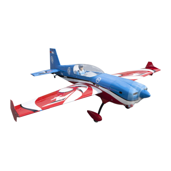
EXTRA 330LX
Code: SEA274
" Graphics and specifications may change without notice " .
Specifications:
Wingspan---------------82.0 in (208.2 cm).
Wing area---------------1349.4 sq.in ( 87.1 sq.dm).
Weight-------------------16.3 -16.8 lbs (7.4- 7.6kg).
Length-------------------77.7 in (197.3 cm).
Engine-------------------50cc-55cc gasoline.
Radio--------------------6 channels with 6 servos.
1
Advertisement
Table of Contents

Related Manuals for Seagull Models EXTRA 330LX


Summary of Contents for Seagull Models EXTRA 330LX
- Page 1 A S S E M B L Y M A N U A L EXTRA 330LX Code: SEA274 “ Graphics and specifications may change without notice ” . Specifications: Wingspan---------------82.0 in (208.2 cm). Wing area---------------1349.4 sq.in ( 87.1 sq.dm). Weight-------------------16.3 -16.8 lbs (7.4- 7.6kg).
-
Page 2: Additional Items Required
You will find that most of the work has been done for you already. The motor mount has been fitted and the hinges are pre-installed. Flying the EXTRA 330LX is simply a joy. This instruction manual is designed to help you build a great flying aeroplane. Please read this manual throughly before starting assembly of your EXTRA 330LX . -
Page 4: Installing The Aileron Servos
EXTRA 330LX Instruction Manual. 2) Layout the servo on the wing to test fit INSTALL THE AILERONS the installation and ensure servo lead is CONTROL HORN. the correct length. Fiberglass control horn 3) Attach the extension to the servo lead and secure with Safety Clip, safety wire, Epoxy. - Page 5 38mm 5) Install servo in servo well with the out- put arm toward the leading edge of the wing. Mark and drill location of servo mounting holes. INSTALLING THE AILERON PUSHROD. Thin CA. M3x15 Socket Head Cap Screw. Flat washer. Lock nut.
-
Page 6: Elevator Servo Installation
EXTRA 330LX Instruction Manual. 100mm Epoxy. Epoxy. Elevator fiberglass control horn. Repeat all the above steps for the other wing. ELEVATOR SERVO INSTALLATION. 1) The elevators have been pre-hinged and glued to the stabs and are ready for flight. No other steps are necessary for hinging. -
Page 7: Elevator Pushrod Installation
5) Install servo with servo mounting screws. 3) Feed servo extension through the el- evator servo mounting hole. 38mm 4) Mark and drill location of servo mounting holes. ELEVATOR PUSHROD INSTALLATION. M3x15 Socket Head Cap Screw. Thin CA. Flat washer. Lock nut. - Page 8 EXTRA 330LX Instruction Manual. Lock nut. Flat washer. Epoxy. M3x15 Socket Head Cap Screw. 38mm Repeat all the above steps for the other elevator. INSTALL RUDDER CONTROL HORN. Use scotch tape to avoid Fiberglass control horn pushrod drop out.
- Page 9 3) Thread the rudder cable through a brass swage tube, then the threaded cou- pler, and back through the brass swage tube on both sides. Pull light tension on the cable through the coupler on both sides as shown. M3x15 Socket Head Cap Screw. Flat washer.
- Page 10 EXTRA 330LX Instruction Manual. 6) Cut off excess cable as shown. 8) Feed one rudder cable through the pre installed cable exit tube in the rear of the fuse toward the front of the fuse. Repeat for other side. 7) Mark and use a 1/16 bit to drill the rudder servo.
- Page 11 12) Crimp the brass swage tube with a NOTE : Cable is installed crossed “ X”, not crimping tool or pliers. parallel. 15) Attach the aluminum tube to com- bine two elevator as below pictures. 13) Cut off excess cable as shown. 14) Attach ball links to the rudder servo arm and then attach the servo arm to the rudder servo as shown.
-
Page 12: Tail Wheel Installation
EXTRA 330LX Instruction Manual. TAILWHEEL INSTALLATION. Locate items necessary to install tail- wheel. M3x15mm M4x15 Socket Head Cap Screw. Fuel Tubing. Washer. Place a drop of Blue Loctite on tail wheel strut mounting screws. Blue Loctite. - Page 13 Attach the steering spring to the rudder Repeat spring installation for other side. control horn. Use pliers to twist spring end closed around rudder control horn. INSTALLING THE MAIN LANDING GEAR TO FUSELAGE. Do same for attachment the steering spring to the rudder tiller. 1) The blind nuts for securing the land- ing gear are already mounted inside the fuselage.
- Page 14 EXTRA 330LX Instruction Manual. M4x25mm Washer. Install gear cover into landing gear. 3x10mm Use lock nut to secure landing gear tighen into fuselage.
- Page 15 Using locknut install axle to gear. Thin CA. 3x10mm Align the wheel pant slot over the axle bolt as shown. Slide the wheel pant slot over the flat sides of the axle bolt and align blind nuts in wheel pants with mounting holes in landing gear.
-
Page 16: Mounting The Engine
EXTRA 330LX Instruction Manual. Install the wheel and outer wheel collar. Use blue Loctite on the wheel collar set screw before final tightening MOUNTING THE ENGINE. NOTE : It’s the canister mount which is used to assemble the canister exhaust sys- tem. -
Page 17: Throttle Servo Installation
Using mounting bolts and washers Use a 1/4 bit to drill the engine mount- mount engine to firewall. ing holes Remove mounting template from fire- Tighten mounting bolts and secure en- wall. Firewall shown with mounting holes gine to firewall. drilled ready for engine mounting. - Page 18 EXTRA 330LX Instruction Manual. Thin CA. 3) Attach throttle pushrod to the carbu- retor throttle arm with the ball link. 4) Install adjustable servo connector in the servo arm as same as picture below: Loctite secure. Adjustable servo connector. Epoxy.
-
Page 19: Ignition Installation
7) Move the throttle stick to the closed po- 3) Thread nylon tie through mounting sition and move the carburetor to closed. holes. Use a 2.5mm hex wrench to tighten the screw that secures the throttle pushrod wire. Make sure to use threadlock on the screw so it does not vibrate loose. -
Page 20: Fuel Tank Assembly
EXTRA 330LX Instruction Manual. Switch. INSTALLING THE ENGINE SWITCH. Trim and cut. INSTALLING THE RECEIVER SWITCH. Install the switch into the precut hole in the side, in the fuselage. Switch. 3/32” Hole. FUEL TANK ASSEMBLY. Please see below pictures. Trim and cut. -
Page 21: Fuel Tank Installation
FUEL TANK INSTALLATION. 1) Install the fuel tubing and clunk. Se- cure the fuel tubing with nylon ties to the pick-up tube and clunk. 2) Insert the rubber stopper assembly Slide the fuel tank into the fuselage. Use into the tank with the vent tube at the top the T-fiting from the fuel dot to connect of the tank. -
Page 22: Muffler Installation
EXTRA 330LX Instruction Manual. COWLING. BATTERY & RECEIVER. 1) Gather the materials as shown below. Install battery using nylon ties and re- ceiver as shown. Battery. 2) Measure and mark the center of the template material as shown. Receiver. MUFFLER INSTALLATION. - Page 23 6) Trace around the head of the engine being careful to keep the template in the same location. 4) Aligning center lines of template and fuse. Tape the template to the bottom of the fuse with the back edge of the tem- plate flush against the aft edge of the re- cessed cowl mounting ring.
- Page 24 EXTRA 330LX Instruction Manual. Note: Take care not to cut or scratch the cowl. 9) Fit template flush with rear of cowl and align center marks of template and cowl. Tape template to the bottom of cowl. Use a felt tip marker to transfer the template...
- Page 25 14) Mark by using a drill to drill the holes for the cowl mounting screws. Then, take cowling out of and drill on it. Make sure the cowl position is correct before drill- ing each hole. Fuel tubing. ELECTRIC POWER CONVERSION. M3x15mm 1) Locate the items neccessary to install Washers.
- Page 26 EXTRA 330LX Instruction Manual. 3) Attach the electric motor box to the firewall suitable with the cross lines drawn on the electric motor box and fire- wall. Using epoxy and balsa stick to se- cure the motor box to the firewall. Please see pictures below.
-
Page 27: Installing The Spinner
Epoxy Battery. 170 mm Open the air exit hole as shown. Balsa stick. Epoxy 5) Attach the speed control to the side of the motor box using two-sided tape and tie wraps. Connect the appropriate leads from the speed control to the mo- tor. - Page 28 EXTRA 330LX Instruction Manual. The propeller should not touch any part of the spinner cone. If it does, use a sharp modeling knife and carefully trim away the spinner cone where the propel- Wing bolt ler comes in contact with it.
- Page 29 2) A scale pilot is included with this ARF. The Pilot included fits well in the cockpit. (or you can order others scale pilot fig- ures made by SG Models. They are avail- able at SG Models distributors.). If you are going to install a pilot figure, please use a sanding bar to sand the base of the figure so that it is flat.
-
Page 30: Apply The Decals
EXTRA 330LX Instruction Manual. 2. The recommended Center of Grav- ity (CG) location for your model is 90– 120mm back from the leading edge at the wing as shown. Mark the location of the CG on the top of the wing at the wing tip. - Page 31 CONTROL THROWS. Aileron (high rate): Aileron (normal rate): 55% exponential 40% exponential Up: 42.0 Degrees Up: 25.5 Degrees Down: 41.0 Degrees Down: 25.0 Degrees Elevator (high rate): Elevator (normal rate): 70% exponential 40% exponential Up: 51.0 Degrees Up: 12.5 Degrees Down: 51.0 Degrees Down 12.5 Degrees Rudder (high rate):...
-
Page 32: Flight Preparation
EXTRA 330LX Instruction Manual. FLIGHT PREPARATION. PREFLIGHT CHECK. 1) Completely charge your trans- Check the operation and direction mitter and receiver batteries before of the elevator, rudder, ailerons and your first day of flying. throttle. 2) Check every bolt and every...
Need help?
Do you have a question about the EXTRA 330LX and is the answer not in the manual?
Questions and answers