Table of Contents
Advertisement
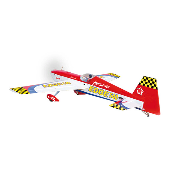
EDGE
Hand-made Almost Ready to Fly R/C Model Aircraft
Specifications
Wingspan---------------------------------------- 68.2 in------------------------- 173.2cm.
Wing area--------------------------------------- 753sq.in-------------------- 48.6 sq.dm.
Approximate flying weight-------------------- 8.4-8.8lbs--------------------- 3.8-4kg.
Length-------------------------------------------- 60.6 in---------------------------- 154cm.
Recommended engine size-----------------.61- .91 cu.in---------------- 2-stroke.
Radio System required 4 channel with 6 digital servos.
Flying skill level Intermediate/advanced.
Kit features.
•
Ready-made—minimal assembly & finishing required.
•
Ready-covered covering.
•
Photo-illustrated step-by-step Assembly Manual.
Made in Vietnam.
ASSEMBLY MANUAL
540
.91-1.00 cu.in---------------- 4-stroke.
Advertisement
Table of Contents

Related Manuals for Seagull Models 540


Summary of Contents for Seagull Models 540
-
Page 1: Specifications
EDGE Hand-made Almost Ready to Fly R/C Model Aircraft ASSEMBLY MANUAL Specifications Wingspan---------------------------------------- 68.2 in------------------------- 173.2cm. Wing area--------------------------------------- 753sq.in-------------------- 48.6 sq.dm. Approximate flying weight-------------------- 8.4-8.8lbs--------------------- 3.8-4kg. Length-------------------------------------------- 60.6 in---------------------------- 154cm. Recommended engine size-----------------.61- .91 cu.in---------------- 2-stroke. .91-1.00 cu.in---------------- 4-stroke. Radio System required 4 channel with 6 digital servos. Flying skill level Intermediate/advanced. -
Page 2: Instruction Manual
Instruction Manual. INTRODUCTION. Thank you for choosing the EDGE 540 ARTF by SEAGULL MODELS. The EDGE 540 was designed with the intermediate/advanced sport flyer in mind. It is a semi scale airplane which is easy to fly and quick to assemble. The airframe is conventionally built using balsa, plywood to make it stronger than the average ARTF , yet the design allows the aeroplane to be kept light. - Page 3 This will ensure proper as- sembly as the EDGE 540 is made from natural materials and minor ad- justments may have to be made. The paint and plastic parts used in this kit are fuel proof.
-
Page 4: Hinging The Ailerons
EDGE 540. Instruction Manual. 4)Deflect the aileron and completely HINGING THE AILERONS. saturate each hinge with thin C/A glue. The ailerons front surface should lightly contact the Note: The control surfaces, including the wing during this procedure. Ideally, when the ailerons, elevators, and rudder, are hinges are glued in place, a 1/64”... -
Page 5: Hinging The Elevators
EDGE 540. Instruction Manual. 8) After both ailerons are securely hinged, firmly grasp the wing panel and aileron to make sure the hinges are securely glued and cannot be pulled out. Do this by carefully applying medium pressure, trying to separate the aileron from the wing panel. -
Page 6: Hinging The Rudder
EDGE 540. Instruction Manual. 6) Using C/A remover/debonder and a paper T-pin. towel, remove any excess C/A glue that may have accumulated on the horizontal stabilizer or in the elevator hinge area. 7) Repeat this process with the other horizontal stabilizer panel, securely hinging the Hinges. -
Page 7: Installing The Aileron Servos
EDGE 540. Instruction Manual. Install the rubber grommets and brass collets onto the aileron servo. Test fit the servo into the aileron servo mount. Install the servo into the servo tray. C/A glue. Secure the servos with the screws pro- vided with your radio system. -
Page 8: Aileron Linkage
EDGE 540. Instruction Manual. Wing panel bottom. Thread. Thread. Electric wire. Electric wire. Plastic tape. Aileron electric. Install the aileron servo tray into the servo mount. Repeat the procedure for orther wing haft. AILERON LINKAGE. INSTALLING THE AILERON LINKAGE. 1) Using a ruler & pen to draw a straight line as below picture. - Page 9 EDGE 540. Instruction Manual. Servo arm. Straigh line. 2) Locate the two nylon control horns, two nylon control horn backplates and two ma- chine screws. 2mm x 30 mm. 7) Pushrod assemble as same as pictures 3) Position the aileron horn on the bottom below: side of aileron.
-
Page 10: Engine Mount
EDGE 540. Instruction Manual. INSTALLING THE BATTERY. Battery. C/A glue. FUEL TANK. INSTALLING THE STOPPER ASSEMBLY. 1) Using a modeling knife, carefully cut off the rear portion of one of the 3 nylon tubes leaving 1/2” protruding from the rear of the stopper. -
Page 11: Mounting The Engine
EDGE 540. Instruction Manual. Vent tube. Fuel pick-up tube. Fuel fill tube. Carefully use a lighter or heat gun to You should mark which tube is the permenently set the angle of the vent tube. vent and which is the fuel pickup when you... - Page 12 EDGE 540. Instruction Manual. 125mm. 4mm X 30mm. 2) Place your engine onto the engine mount. Adjust the engine is centered of the edges of the engine case. 3) When you are satisfied with the align- ment, mark the locations of the engine mounting.
- Page 13 EDGE 540. Instruction Manual. (2) Washer. (2) Wheel Collar. Axle. Nut. Wheel. 2) Follow diagram below for wheel pant Nut. installation: (2) Washer. Wheel Collar. Axle. Nut. Nut. Wheel. Landing Gear. Landing gear. Wheel Pant. 10mm. 3) You have to trim each axle using a toll cutting and cut-off wheel.
-
Page 14: Installing The Main Landing Gear
EDGE 540. Instruction Manual. 3mmX10mm. 4) A drop of C/A glue on the wheel collar screws will help keep them from coming lose Trim and cut. during operation. Repeat the process for the other wheel. INSTALLING THE MAIN LANDING GEAR. -
Page 15: Installing The Spinner
EDGE 540. Instruction Manual. 3mm X 10mm (6pcs). 1.5mm wire (needle valve). INSTALLING THE SPINNER. 1) Install the spinner backplate, propeller and spinner cone. The spinner cone is held in place using two 3mm x 15mm wood screws. (spinner is not included). -
Page 16: Elevator - Rudder Servo Installation
EDGE 540. Instruction Manual. ELEVATOR - RUDDER SERVO Center line. INSTALLATION. Locate and cut out the covering film from the servo holes in both sides of fuselage. 2) Using a modeling knife, carefully re- move the covering at mounting slot of horizon- tal stabilizer ( both side of fuselage). -
Page 17: Vertical Stabilizer Installation
EDGE 540. Instruction Manual. Remove covering. Covered wood When cutting through the covering filler piece. to remove it, cut with only enough pres- sure to only cut through the covering it- self. Cutting into the balsa structure may weaken it. -
Page 18: Control Horn Installation
EDGE 540. Instruction Manual. 5) Slide the vertical stabilizer back in place. Using a triangle, check to ensure that the vertical stabilizer is aligned 90º to the hori- zontal stabilizer. Vertical Stabilizer. Horizontal 90º Stabilizer. 6) When you are sure that everything is... - Page 19 EDGE 540. Instruction Manual. 2) Position the elevator horn on the both Elevator control horn. side of elevator. The clevis attach- ment holes should be positioned over the hinge line. 2mm x 20 mm. Rudder control horn. ELEVATOR-RUDDER PUSHROD INSTALLATION.
- Page 20 EDGE 540. Instruction Manual. Right side. 2mm X 20mm. Control clasp. 2 screws. MOUNTING THE TAIL WHEEL BRACKET. INSTALLING TAIL STRUT SYSTEM. 1) Set the tail wheel assembly in place on the plywood plate. The pivot point of the tail...
-
Page 21: Installing The Switch
EDGE 540. Instruction Manual. INSTALLING THE SWITCH. Install the switch into the precut hole in the servo tray, in the fuselage, from the bottom. Use the two screws provided with the switch 3x10mm. to secure it in place. Drill two 3/32” holes through the tray for the screws to pass through. -
Page 22: Installing The Receiver
EDGE 540. Instruction Manual. Adjustable Servo connector. Receiver. Servo arm. 2) Install the rubber grommets and brass collets onto the throttle servo. Test fit the servo into the aileron servo mount. Because the size of servos differ, you may need to adjust the size of the precut opening in the mount. -
Page 23: Control Throws
CONTROL THROWS. We highly recommend setting up the EDGE 540 using the control throws listed at right. We have listed control throws for both Low Rate (initial test flying/sport flying) and High Rate (aerobatic flying). -
Page 24: Flight Preparation
3/4” down flying. Rudder: 2 1/2” right and left 2) Check every bolt and every glue joint AEROBATIC FLYING in the EDGE 540 to ensure that everything is tight and well bonded. Ailerons: 1” up 7/8” down Elevator: 1 1/4” up 1 1/4”down... - Page 25 EDGE 540. Instruction Manual.
- Page 26 EDGE 540. Instruction Manual.
Need help?
Do you have a question about the 540 and is the answer not in the manual?
Questions and answers