Table of Contents
Advertisement
ASSEMBLY MANUAL
WWW.SEAGULLMODELS.COM
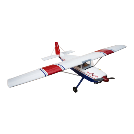
MAXI LIFT
33cc
MS: 209
" Graphics and specifications may change without notice " .
Specifications:
Wingspan---------------87.6 in (222.2 cm).
Wing area----------------1072.6sq.in (69.2 sq.dm).
ALMOST
Weight-------------------11.5 - 12.1 lbs (5.2 - 5.5 kg).
READY TO FLY
Length-------------------61.2 in (155.5cm).
Recommended engine size 33cc...............................
Radio--------------------7 channels with 10 servos.
Flying skill level intermediate/ advanced
www.seagullmodels.com
1
Advertisement
Table of Contents

Subscribe to Our Youtube Channel
Related Manuals for Seagull Models MAXI LIFT 33cc


Summary of Contents for Seagull Models MAXI LIFT 33cc
- Page 1 ASSEMBLY MANUAL WWW.SEAGULLMODELS.COM MAXI LIFT 33cc MS: 209 “ Graphics and specifications may change without notice “ . Specifications: Wingspan---------------87.6 in (222.2 cm). Wing area----------------1072.6sq.in (69.2 sq.dm). ALMOST Weight-------------------11.5 - 12.1 lbs (5.2 - 5.5 kg). READY TO FLY Length-------------------61.2 in (155.5cm). Recommended engine size 33cc.......
-
Page 2: Kit Contents
Instruction Manual. INTRODUCTION. Thank you for choosing the MAXI LIFT ARTF by SEAGULL MODELS COMPANY LTD,. The MAXI LIFT was designed with the intermediate/advanced sport flyer in mind. It is a semi scale airplane which is easy to fly and quick to assemble. The airframe is onventionally built using balsa, plywood to make it stronger than the average ARTF, yet the design allows the aeroplane to be kept light. -
Page 3: Additional Items Required
WWW.SEAGULLMODELS.COM KIT CONTENTS. HINGING THE FLAP SEA20901 Fuselage SEA20902 Wing Set SEA20903 Tail Set SEA20904 Fiberglass Cowling SEA20905 Canopy SEA20906 Landing Gear SEA20907 Wheels SEA20908 Wing struts SEA20909 Pilot ADDITIONAL ITEMS REQUIRED. M2x10 mm 0.75- 0.91 2-stroke. 0.91-1.25 4-stroke. 33cc gasoline engine. Computer radio with 10 servos. -
Page 4: Hinging The Elevator
MAXI LIFT Instruction Manual. NOTE : The hinge is constructed of a spe- HINGING THE ELEVATOR. cial material that allows the C/A to wick Note : The control surfaces, including the ai- or penetrate and distribute throughout lerons, elevators, and rudder, are prehinged the hinge, securely bonding it to the wood with hinges installed, but the hinges are not structure of the wing panel and aileron. -
Page 5: Hinging The Rudder
WWW.SEAGULLMODELS.COM 7) Repeat this process with the other wing panel, securely hinging the aileron in place. 8) After both ailerons are securely hinged, firmly grasp the wing panel and aileron to make sure the hinges are securely glued and cannot be pulled out. Do this by carefully ap- plying medium pressure, trying to separate Epoxy the aileron from the wing panel. -
Page 6: Installing The Main Landing Gear
MAXI LIFT Instruction Manual. INSTALL RUDDER CONTROL HORN. Repeat steps to install the rudder control horn as same as steps done for ailerons. Epoxy Aileron control horn. INSTALL ELEVATOR CONTROL HORN. Epoxy Fiberglass control horn. Epoxy Rudder control horn. Epoxy INSTALLING THE MAIN LANDING GEAR. -
Page 7: Installing The Fuselage Servos
WWW.SEAGULLMODELS.COM Collar. 4x20 mm INSTALLING THE FUSELAGE SERVOS. Because the size of servos differ, you may need to adjust the size of the precut opening in the mount. The notch in the sides of the mount allow the servo lead to pass through. 1) Install the rubber grommets and brass collets onto the throttle servo. -
Page 8: Installing The Switch
MAXI LIFT Instruction Manual. INSTALLING THE SWITCH. Install the switch into the precut hole in the side, in the fuselage. 3/32” Hole. Elevator servo arm. Trim and cut Rudder servo. Servo tow. Switch for engine. Servo capping. Trim and cut... -
Page 9: Mounting The Engine
WWW.SEAGULLMODELS.COM 5) Slide the pushrod tube in the firewall and guide it through the fuel tank mount. Use medium C/A to glue the tube to the firewall and the fuel tank mount. 6) Connect the Z-bend in the 600mm throt- tle pushrod to the outer hole of the carbure- tor arm. -
Page 10: Installing The Stopper Assembly
MAXI LIFT Instruction Manual. THROTTLE SERVO ARM INSTALLA- TION. Install adjustable servo connector in the servo arm as same as picture below: Adjustable Servo Loctite secure. connector. Servo arm. 1 PCS INSTALLING THE STOPPER ASSEMBLY. 1) Using a modeling knife, carefully cut off the rear portion of one of the 3 nylon tubes leaving 1/2”... -
Page 11: Fuel Tank Installation
WWW.SEAGULLMODELS.COM 5) With the stopper assembly in place, the weighted pick-up should rest away from the rear of the tank and move freely inside the tank. The top of the vent tube should rest just below the top of the tank. It should not touch the top of the tank. - Page 12 MAXI LIFT Instruction Manual. Vent tube. Fuel pick up tube. Fuel fill tube. 9) Connect the lines from the tank to the en- gine and muffler. The vent line will connect to the muffler and the line from the clunk to the carburetor.
-
Page 13: Installing The Spinner
WWW.SEAGULLMODELS.COM INSTALLING THE SPINNER. Install the spinner backplate, propeller and spinner cone. 2) While keeping the back edge of the cowl flush with the marks, align the front of the cowl with the crankshaft of the engine. The front of the cowl should be positioned so the crankshaft is in nearly the middle of the cowl opening. - Page 14 MAXI LIFT Instruction Manual. 1) Using a small weight (Weighted fuel pick- up works well) and string, feed the string through the wing as indicated. 2) Place the servo between the mounting 6) Secure the servo to the aileron hatch using blocks and space it from the hatch.
- Page 15 WWW.SEAGULLMODELS.COM AILERON PUSHROD HORN INSTALLATION. 100mm. M3 clevis. M3 lock nut. Wing 9) Set the aileron hatch in place and use a Phillips screw driver to install it with four INSTALLING THE FLAP SERVO. wood screws. Repeat the procedure for the aileron servo.
- Page 16 MAXI LIFT Instruction Manual. 90mm. M3 clevis. M3 lock nut. Wing INSTALLING TOW RELEASE FOR SAIL PLANE. It is best to operate the aero-tow release mechanism using a momentary switch Screw the aero-tow mechanism into the mounted on the joystick. The servo travel hole just behind the canopy, and apply must be set accordingly.
-
Page 17: Installing The Horizontal Stabilizer
WWW.SEAGULLMODELS.COM INSTALLING THE HORIZONTAL STABILIZER. - Page 18 MAXI LIFT Instruction Manual. 1) Using a ruler and a pen, locate the center- line of the horizontal stabilizer, at the trail- Remove the covering. ing edge, and place a mark. Use a triangle and extend this mark, from back to front, across the top of the stabilizer.
- Page 19 WWW.SEAGULLMODELS.COM 3) While holding the vertical stabilizer firm- ly in place, use a pen and draw a line on each side of the vertical stabilizer where it meets the top of the fuselage. INSTALLING VERTICAL FIN. 4) Remove the stabilizer. Using a modeling knife, remove the covering from below the lines you drew.
- Page 20 MAXI LIFT Instruction Manual. 6) When you are sure that everything is aligned correctly, mix up a generous amount of Flash 30 Minute Epoxy. Apply a thin lay- er to the mounting slot and to bottom of the vertical stabilizer mounting area. Ap- ply epoxy to the bottom and top edges of the filler block and to the lower hinge also.
- Page 21 WWW.SEAGULLMODELS.COM M3 clevis. Crimp. Metal connector. Cable end. THE TAIL WHEEL - STRUT SUPPORT. Locate items necessary to install tail wheel. 100mm 3x25 mm. Bend at the mark. Aluminum tail landing gear. 3 x 20mm.
- Page 22 MAXI LIFT Instruction Manual. Bend at the mark. INSTALLING TAIL STRUT SUPPORT. The tail strut system assembly follow pic- tures below. 100mm...
-
Page 23: Apply The Decals
WWW.SEAGULLMODELS.COM INSTALLATION PILOT AND CANOPY. 1) Locate items necessary to install pilot and canopy. Epoxy. 2) A scale pilot is included with this ARF. The Seagull Pilot included fitting well to the cockpit. (or you can order others scale pilot figures made by Seagull fac- tory. - Page 24 MAXI LIFT Instruction Manual. 2) If all the decals are not precut, please use Insert two wing panels as pictures below. scissors or a sharp hobby knife to cut the decals from the sheet. Please be c ertain the model is clean and free from oily fingerprints and dust.
- Page 25 WWW.SEAGULLMODELS.COM INSTALLATION WING- FUSELAGE STRUTS. M3x25mm Fuselage. Wing. Wing. M3x25mm Wing.
-
Page 26: Control Throws
MAXI LIFT Instruction Manual. Lift the model. If the tail drops when you BALANCING. lift, the model is “tail heavy” and you must add weight* to the nose. If the nose 1) It is critical that your airplane be bal- drops, it is “nose heavy”... -
Page 27: Flight Preparation
WWW.SEAGULLMODELS.COM FLIGHT PREPARATION. PREFLIGHT CHECK. Check the operation and direction of the 1) Completely charge your transmitter and elevator, rudder, ailerons and throttle. receiver batteries before your first day of flying. A) Plug in your radio system per the 2) Check every bolt and every glue joint in manufacturer’s instructions and turn eve- the MAXI LIFT to ensure that everything is rything on.
Need help?
Do you have a question about the MAXI LIFT 33cc and is the answer not in the manual?
Questions and answers