Table of Contents
Advertisement
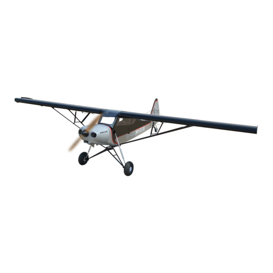
Code : SEA 357
ASSEMBLY MANUAL
Specifications:
Wingspan--------------- 102.0 in (259.0 cm).
Wing area--------------- 1802.7 sq.ins (1163.0 sq.dm).
Weight------------------- 21.0 lbs (9.6 kg).
Length------------------- 68.2 in (173.3 cm).
Engine/Motor size----- 35-55cc gasoline.
Radio--------------------- 7 channels with 8 servos.
1
Advertisement
Table of Contents

Related Manuals for Seagull Models SHOCK-CUB 35-55cc


Summary of Contents for Seagull Models SHOCK-CUB 35-55cc
- Page 1 Code : SEA 357 ASSEMBLY MANUAL Specifications: Wingspan--------------- 102.0 in (259.0 cm). Wing area--------------- 1802.7 sq.ins (1163.0 sq.dm). Weight------------------- 21.0 lbs (9.6 kg). Length------------------- 68.2 in (173.3 cm). Engine/Motor size----- 35-55cc gasoline. Radio--------------------- 7 channels with 8 servos.
- Page 2 SHOCK CUB 35-55cc Instruction Manual. INTRODUCTION Thank you for choosing the SHOCK CUB 35-55cc ARTF by SG MODELS . The SHOCK CUB 35-55cc was designed with the intermediate/advanced sport flyer in mind. It is a semi scale airplane which is easy to fly and quick to assemble. The air- frame is conventionally built using balsa, plywood to make it stronger than the av- erage ARTF, yet the design allows the aeroplane to be kept light.
- Page 3 HYPER-STOLAIRFOIL & HIGH KIT CONTENTS LIFT DEVICES SEA 357 SHOCK CUB 35-55cc Please see below pictures. 1. Fuselage 2. Wing set (2) 3. Tail set (2) 4. Canopy and Window 5. Cowling 6. Wing tube 7. Wing tip 8. landing gear 9.
- Page 4 SHOCK CUB 35-55cc Instruction Manual. Epoxy Epoxy...
- Page 5 Flap control horn Ailerons control horn Use sandpaper to scuff the bottom of the aileron and flap control horns. Use a paper towel and isopropyl alcohol to remove any oils or debris from the control horns. Check the fit of the control horns to the ai- leron and flap.
- Page 6 SHOCK CUB 35-55cc Instruction Manual. Place low-tack tape 1/32 inch (1mm) from the control horn slot. This will pre- vent epoxy from getting on the control Epoxy surface when the control horns are glued in place. Before the epoxy fully cures, remove the tape from around the control horn.
- Page 7 Minimum servo spec. Torque : 122 oz-in (8.8 kg-cm) @ 6.0V; 139 oz-in (10.0 kg-cm) @ 7.4V Epoxy Because the size of servos differ, you may need to adjust the size of the precut opening in the mount. The notch in the sides of the mount allow the servo lead to pass through.
- Page 8 SHOCK CUB 35-55cc Instruction Manual. Remove the string from the wing at the servo location and use the tape to attach it to the servo extension lead. Pull the lead through the wing and remove the string. C/A glue Use dental floss to secure the connec- tion so they cannot become unplugged.
- Page 9 Set the aileron hatch in place and use a Phillips screw driver to install it with four wood screws. 140mm M3x10mm M3 clevis M3 lock nut 162mm INSTALLING THE FLAP SERVO AILERON PUSHROD INSTALLATION Repeat the procedure for the flap servo. Please see below pictures.
- Page 10 SHOCK CUB 35-55cc Instruction Manual. 175mm M3 lock nut M3 clevis M3x10mm 192mm...
- Page 11 INSTALLING THE FUSELAGE SERVOS 3/32” Hole Because the size of servos differ, you may need to adjust the size of the precut opening in the mount. The notch in the sides of the mount allow the servo lead to pass through. Install the rubber grommets and brass collets into all servos.
- Page 12 SHOCK CUB 35-55cc Instruction Manual. Switch INSTALLING THE MAIN LANDING GEAR TO FUSELAGE Please see below pictures.
- Page 13 Epoxy M3x15mm...
- Page 14 SHOCK CUB 35-55cc Instruction Manual. M3x15mm...
- Page 15 4x5mm...
- Page 16 SHOCK CUB 35-55cc Instruction Manual. Collar Carefully bend the second nylon tube up at a 45º angle. This tube is the vent tube. Test fit the stopper assembly into the tank. It may be necessary to remove some of the flashing around the tank opening using a modeling knife.
- Page 17 You should mark which tube is the vent and which is the fuel pickup when you attach fuel tubing to the tubes in the stopper. Once the tank is installed inside the fuselage, it may be difficult to determine which is which. MOUNTING THE ENGINE Please see below pictures.
- Page 18 SHOCK CUB 35-55cc Instruction Manual. M5x90mm Balsa wood Epoxy Vent tube Fuel pick up tube Fuel fill tube 160mm Connect the lines from the tank to the engine and muffler. The vent line will connect to the muffler and the line from the clunk tothe carburetor.
- Page 19 COWLING Please see below pictures. Use a drill and drill bit to drill the holes for the cowl mounting screws. Make sure the cowl position is correct before drill- ing each hole. Tape the cowl to the fuselage using low-tack tape.
- Page 20 SHOCK CUB 35-55cc Instruction Manual. ELECTRIC POWER CONVERSION Locate the items neccessary to install the electric power conversion included M3x10mm with your model. Because of the size of the cowl, it may be nec- essary to use a needle valve extension for the high speed needle valve.
- Page 21 Mark Attach the motor mount to the front of the electric motor box using four 5mm blind nut, four M5x30mm hex head bolts to se- cure the motor. Please see picture shown.
- Page 22 SHOCK CUB 35-55cc Instruction Manual. M5x30mm and washers Blind nut M5x20mm Then, use 7mm drill bit to enlarge the holes on the electric motor box. Epoxy...
- Page 23 Attach the speed control to the side M3x10mm of the motor box using two-sided tape and tie wraps. Connect the appropriate leads from the speed control to the mo- tor. Make sure the leads will not interfere with the operation of the motor. 160mm M6 Nylon...
- Page 24 SHOCK CUB 35-55cc Instruction Manual. M6 Nylon INSTALLING THE SPINNER Install the spinner backplate, propeller and spinner cone. The propeller should not touch any part of the spinner cone. If it does, use a sharp modeling knife and carefully trim away the spinner cone where the propel- ler comes in contact with it.
- Page 25 HINGING THE ELEVATORS ELEVATOR AND STABILIZER INSTALLATION Glue the elevator hinges in place using the same techniques used to hinge the ai- lerons. With the stabilizer held firmly in place, use a pen and draw lines onto the stabi- INSTALL ELEVATOR CONTROL HORN lizer where it and the fuselage sides meet.
- Page 26 SHOCK CUB 35-55cc Instruction Manual. When cutting through the covering to remove it, cut with only enough pressure to only cut through the covering itself. Cut- ting into the balsa structure may weaken Using a modeling knife, carefully remove the covering that overlaps the stabilizer mounting platform sides in the fuselage.
- Page 27 Fit the elevator so the leading edge fis If you find epoxy on the joiner wire, use tightly against the trailing edge of the sta- the paper towel and isopropyl alcohol to bilizer. clean the joiner. Use a pin vise and 1/16-inch (1.5mm) drill bit to drill a hole in the center of each hinge slot to allow the CA to wick Check the fit of both elevators at this...
- Page 28 SHOCK CUB 35-55cc Instruction Manual. Flex the elevator slightly, making sure INSTALL RUDDER CONTROL HORN to keep the gap between the elevator and stabilizer as narrow as possible. Saturate Repeat steps to install the rudder control each of the hinges using thin CA. Apply horn as same as steps done for ailerons.
- Page 29 Thread one clevis and M2 lock nut on to each elevator control rod. Thread the horns on until they are flush with the C/A glue ends of the control rods. Elevator and rudder pushrods assembly as pictures below. Locate items necessaryto install rudder pushrod.
- Page 30 SHOCK CUB 35-55cc Instruction Manual. RUDDER PUSHROD MOUNTING THE TAIL WHEEL INSTALLATION Repeat steps as same as steps done for Locate items necessary to install tail wheel. elevator. M3x20mm M3x10mm...
- Page 31 M3x10mm M3x10mm...
- Page 32 SHOCK CUB 35-55cc Instruction Manual. INSTALL BRACING WIRE AND METAL BRACKET AT THE TAIL TOP VIEW. M3x15mm...
- Page 33 M3x20mm BOTTOM VIEW.
- Page 34 SHOCK CUB 35-55cc Instruction Manual. Receiver Two batteries INSTALL THE WINDOW Parts requirement.See pictures below. INSTALLING BATTERY - RECEIVER Plug the servos leads and the switch lead into the receiver. Plug the battery pack lead into the switch also. Wrap the receiver and battery pack in the protective foam rubber to protect them from vibration.
- Page 35 Epoxy Epoxy...
- Page 36 SHOCK CUB 35-55cc Instruction Manual.
- Page 37 M2x8mm INSTALLATION CANOPY AND CHAIR Epoxy Locate items necessary to install canopy and chair.
- Page 38 SHOCK CUB 35-55cc Instruction Manual. Epoxy M3x15mm INSTALLATION WING STRUTS M3x15mm Loacte the items for this section of the manual.
- Page 39 Diagonal brace M3x15mm Socket Head Cap Screw Nylon washer Nylon washer M3 locknut Front...
- Page 40 SHOCK CUB 35-55cc Instruction Manual. 167mm 108mm...
- Page 41 INSTALL WING TIP Locate items necessary to install. 140mm M3x10mm...
- Page 42 SHOCK CUB 35-55cc Instruction Manual. ATTACHMENT WING- FUSELAGE. M3x10mm Attach the aluminium tube into fuselage. Wing tube M3x10mm...
- Page 43 M4x15mm M3x15mm M4x15mm Wing bolt...
- Page 44 SHOCK CUB 35-55cc Instruction Manual. Open the window M3x10mm M3x15mm...
- Page 45 *If possible, first attempt to balance the APPLY THE DECALS model by changing the position of the 1) If all the decals are precut and ready to receiver battery and receiver. If you are stick. Please be certain the model is clean unable to obtain good balance by doing and free from oily fingerprints and dust.
- Page 46 SHOCK CUB 35-55cc Instruction Manual. 120mm CONTROL THROWS Rudder: Ailerons: High Rate : High Rate : Up : 70 mm Right : 100 mm Down : 70 mm Left : 100 mm Low Rate : Low Rate : Up : 40 mm Right : 60 mm Down : 40 mm Left : 60 mm...
- Page 47 40-80mm 40-80mm 60-100mm Fuselage 60-100mm 40-70mm Wing 40-70mm 30mm 80mm...
- Page 48 SHOCK CUB 35-55cc Instruction Manual. FLIGHT PREPARATION PREFLIGHT CHECK 1) Completely charge your trans- Check the operation and direction mitter and receiver batteries before of the elevator, rudder, ailerons and your first day of flying. throttle. 2) Check every bolt and every glue A) Plug in your radio system per the joint in the to en-...
- Page 49 If you have any queries, or are interested in our products, please feel free to contact us Factory : 12/101A - Hamlet 4 - Le Van Khuong Street - Dong Thanh Ward - Hoc Mon District - Ho Chi Minh City - Viet Nam. Office : 62/8 Ngo Tat To Street - Ward 19 - Binh Thanh District - Ho Chi Minh City - Viet Nam Phone : 848 - 86622289 or 848- 36018777...
Need help?
Do you have a question about the SHOCK-CUB 35-55cc and is the answer not in the manual?
Questions and answers