Table of Contents
Advertisement
Quick Links
Download this manual
See also:
Instruction Manual
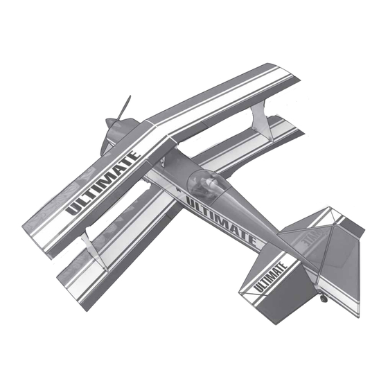
ULTIMATE
ASSEMBLY MANUAL
"Graphics and Specfications may change without notice".
Specifications
Wingspan --------------------------------------------- 43 in --------------------------- 109cm.
Wing area --------------------------------------- 589 sq.in ------------------------ 38 sq.dm.
Weight ------------------------------------------------ 6-7lbs ----------------------- 2.7-3.2kg.
Length ------------------------------------------------- 44.8in ------------------------ 113.7cm.
Recommended engine size ---------- .46-.55 cu.in --------------------------- 2-stroke.
Radio System required 6 channel with 6 servos.
Flying skill level -------------------Intermediate/advanced.
Kit features.
•
Ready-made—minimal assembly & finishing required.
•
Ready-covered covering.
•
Photo-illustrated step-by-step Assembly Manual.
Made in Vietnam.
.72-.82 cu.in -------------------------- 4-stroke.
MS:63
Advertisement
Table of Contents

Related Manuals for Seagull Models Ultimate


Summary of Contents for Seagull Models Ultimate
- Page 1 ULTIMATE ASSEMBLY MANUAL MS:63 “Graphics and Specfications may change without notice”. Specifications Wingspan --------------------------------------------- 43 in --------------------------- 109cm. Wing area --------------------------------------- 589 sq.in ------------------------ 38 sq.dm. Weight ------------------------------------------------ 6-7lbs ----------------------- 2.7-3.2kg. Length ------------------------------------------------- 44.8in ------------------------ 113.7cm. Recommended engine size ---------- .46-.55 cu.in --------------------------- 2-stroke.
-
Page 2: Fuselage Assembly
ARTF , yet the design allows the aeroplane to be kept light. You will find that most of the work has been done for you already.Flying the ULTIMATE is simply a joy. This instruction manual is designed to help you build a great flying aeroplane. Please read this manual thoroughly before starting assembly of your ULTIMATE. -
Page 3: Hinging The Ailerons
Please trial fit all parts. Make sure you have the correct parts and that they fit and are aligned properly before gluing! This will ensure proper as- sembly as the ULTIMATE is made Hinge. from natural materials and minor ad- justments may have to be made. -
Page 4: Installing The Aileron Servos
ULTIMATE. Instruction Manual. 5) Turn the wing panel over and deflect the aileron in the opposite direction from the opposite side. Apply thin C/A glue to each hinge, making sure that the C/A penetrates into both the aileron and wing panel. - Page 5 www.seagullmodels.com Lower wing bottom. Thread. Remove covering. Small weight. Servo tray. C/A glue. Attach the string to the servo lead and carefully thread it though the wing. Once you have thread the lead throught the wing, remove the string so it can use for the other servo Servos.
-
Page 6: Installing The Aileron Linkage
ULTIMATE. Instruction Manual. 2) Locate the nylon control horns,nylon control horn backplates and two machine screws. 3) Position the aileron horn on the bottom side of aileron. 2x20mm. Lower wing bottom. Lower wing panel bottom. Thread. Control Horn. Electric wire. - Page 7 www.seagullmodels.com Lower wing bottom. Mark point. Repeat the procedure for the other aileron servo. INSTALLING THE TURNBUCKLE Cut. (LOWER WING). Installing the turnbuckle for aileron linkage of lower wing as same as pictures below. 3x30mm. 7 mm Lower wing bottom. M2 lock nut.
-
Page 8: Engine Mount
ULTIMATE. Instruction Manual. Repeat the procedure for the other Lower wing wing haft. bottom. PLASTIC STRAP INSTALLATION UPPER WING. Repeat the procedure as same as lower wing. See pictures below. Grind. Slot. Lower wing bottom. Upper wing bottom. Upper wing bottom. -
Page 9: Installing The Battery
www.seagullmodels.com Thread locker. INSTALLING THE BATTERY Battery. Vent tube. Fuel pick up tube. FUEL TANK. INSTALLING THE STOPPER ASSEMBLY. Fuel fill tube. 1) Using a modeling knife, carefully cut off the rear portion of one of the 3 nylon tubes leaving 1/2”... - Page 10 ULTIMATE. Instruction Manual. Vent tube. 6) When satisfied with the alignment of the stopper assembly tighten the 3 x 20mm Fuel pick-up tube. machine screw until the rubber stopper ex- pands and seals the tank opening. Do not overtighten the assembly as this could cause the tank to split.
-
Page 11: Installing The Main Landing Gear
www.seagullmodels.com 5mm. 10mm. 3) You have to trim each axle using a tool cutting and cut-off wheel. Caution when cutting the axles and wear protective goggles. 46mm. 4) A drop of C/A glue on the wheel collar screws will help keep them from coming lose during operation. - Page 12 ULTIMATE. Instruction Manual. 2) Place your engine onto the engine mount. Adjust the engine is centered of the edges of the engine case. 3) When you are satisfied with the align- ment, mark the locations of the engine mounting. 4) Remove the engine. Using an drill bit, drill the mounting holes through the engine mount at the four locations marked.
-
Page 13: Installing The Switch
www.seagullmodels.com 3) Install the muffler and muffler extension onto the engine and make the cutout in the cowl for muffler clearance. Connect the fuel and pressure lines to the carburetor, muffler and fuel filler valve. Secure the cowl to fuse- lage using the 3x10mm screws (4). -
Page 14: Horizontal Stabilizer
ULTIMATE. Instruction Manual. THROTTLE SERVO ARM INSTALLATION. Center line. ) Install adjustable servo connector in the servo arm. Adjustable servo Servo arm. connector. 2) Using a modeling knife, carefully remove the covering at mounting slot of horizontal sta- Thread locker glue. -
Page 15: Vertical Stabilizer Installation
www.seagullmodels.com When cutting through the covering to re- VERTICAL STABILIZER INSTALLATION. move it, cut with only enough pressure to only cut through the covering itself. Cutting into the balsa structure may weaken it. 6) Using a modeling knife, carefully re- move the covering that overlaps the stabilizer mounting platform sides in the fuselage. -
Page 16: Control Horn Installation
ULTIMATE. Instruction Manual. Set the stabilizer in place and realign. Double check all of your measurements once more be- fore the epoxy cures. Hold the stabilizer in place Pen. with T-pins or masking tape and remove any excess epoxy using a paper towel and rubbing alcohol. -
Page 17: Mounting The Tail Wheel Bracket
www.seagullmodels.com 2) Elevator pushrods assembly follow Control Horn. pictures below. Elevator pushrod. Fin. Elevator. Control horn. Clevis. Mounting Screws. Mounting Plate. 4) Install the rudder control horn using the same method as with the elevator control Rudder pushrod. horns. Elevator control horn. Right side. -
Page 18: Cabane Strut Installation
ULTIMATE. Instruction Manual. Antenna. MOUNTING THE CONTROL CLASP. CABANE STRUT INSTALLATION. See pictures below: (B) 3x10mm(4pcs). 2x20mm. 1) Remove the covering in the top of the fuselage for the cabane struts. 2) Slide the cabane into position. Control clasp. 2 screws. - Page 19 www.seagullmodels.com Lower wing. THE CENTER RIB INSTALLATION. Rib center (2) 3x10cm. Wing bolts. ATTACHMENT WING. See pictures below: Upper wing. (D) Lower wing tube:36.3cm. (E) Upper wing tube: 24.5cm. 2 sets.
- Page 20 ULTIMATE. Instruction Manual. AIRFOIL STRUT INSTALLATION. Place on strut into position. Make sure the curves on the strut follow the airfoil of the wings. Upper wing bottom. INSTALLING THE AILERON LINKAGE (UPPER-LOWER MAIN WING). Parts requirement. See pictures below: 1.8x180mm.
-
Page 21: Control Throws
CG=10-13cm. CONTROL THROWS. We highly recommend setting up the ULTIMATE using the control throws listed at right. We have listed control throws for both Low Rate (initial test flying/sport flying) and High Rate (aerobatic flying). INSTALLING THE CANOPY HATCH. -
Page 22: Flight Preparation
2) Check every bolt and every glue joint in the ULTIMATE to ensure that everything is tight and well bonded. 3) Double check the balance of the air- plane. Do this with the fuel tank empty. - Page 23 www.seagullmodels.com FOR USA MARKET ONLYLY. Warranty Period: Exclusive Warranty- Horizon Hobby, Inc., (Horizon) warranties that the Products purchased (the “Product”) will be free from defects in materials and workmanship at the date of purchase by the Purchaser. Limited Warranty (a) This warranty is limited to the original Purchaser (“Purchaser”) and is not transferable. REPAIR OR REPLACEMENT AS PROVIDED UNDER THIS WARRANTY IS THE EXCLUSIVE REMEDY OF THE PURCHASER.
- Page 24 ULTIMATE. Instruction Manual. Warranty Inspection and Repairs To receive warranty service, you must include your original sales receipt verifying the proof-of-purchase date. Provided warranty conditions have been met, your Product will be repaired or replaced free of charge. Repair or replacement decisions are at the sole discretion of Horizon Hobby.
Need help?
Do you have a question about the Ultimate and is the answer not in the manual?
Questions and answers