Table of Contents
Advertisement
Quick Links
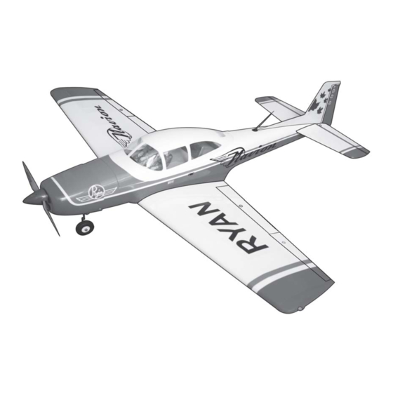
RYAN NAVION
ASSEMBLY MANUAL
"Graphics and specifications may change without notice".
Specifications:
Wing span ----------------------------------------------63 in---------------------------------------- 160cm.
Wing area --------------------------------------------- 768.8sq.in-------------------------- 49.6 sq.dm.
Approximate flying weight ------------------------ 7.9-8.8 lbs --------------------------------3.6-4.0kg.
Length ------------------------------------------------- 54.8 in -----------------------------------139.2cm.
Recommended engine size ---------------------- 0.75-0.91 cu.in ----------------------------2-stroke.
ELECTRIC CONVERSION : OPTIONAL.
Recommended R/C -------------------------------------------- 6 channels with 8 servos.
Flying skill level ----------------------------------------------------- Advanced/Intermediate.
Kit features.
•
Ready-made—minimal assembly & finishing required.
•
Ready-covered—including decals, trim & covering.
•
Photo-illustrated step-by-step Assembly Manual.
.91-1.00 cu.in ---------------------------4-stroke.
MS:106
Made in Vietnam.
Advertisement
Table of Contents

Related Manuals for Seagull Models Ryan Navion


Summary of Contents for Seagull Models Ryan Navion
- Page 1 RYAN NAVION MS:106 ASSEMBLY MANUAL “Graphics and specifications may change without notice”. Specifications: Wing span ----------------------------------------------63 in---------------------------------------- 160cm. Wing area --------------------------------------------- 768.8sq.in-------------------------- 49.6 sq.dm. Approximate flying weight ------------------------ 7.9-8.8 lbs --------------------------------3.6-4.0kg. Length ------------------------------------------------- 54.8 in -----------------------------------139.2cm. Recommended engine size ---------------------- 0.75-0.91 cu.in ----------------------------2-stroke.
-
Page 2: Instruction Manual
. Flying the RYAN NAVION is simply a joy. This instruction manual is designed to help you build a great flying aeroplane. Please read this manual thoroughly before starting assembly of your RYAN NAVION . Use the parts listing below to identify all parts. - Page 3 3) Slide the aileron on the wing panel until gluing! This will ensure proper as- there is only a slight gap. The hinge is now sembly as the RYAN NAVION is centered on the wing panel and aileron. made from natural materials and...
-
Page 4: Hinging The Rudder
Instruction Manual. RYAN NAVION HINGING THE RUDDER. Glue the rudder hinges in place using the same techniques used to hinge the ailerons. 5) Turn the wing panel over and deflect the aileron in the opposite direction from the opposite side. Apply thin C/A glue to each hinge, making sure that the C/A penetrates into both the aileron and wing panel. - Page 5 www.seagullmodels.com Install the wing edge to the wing. CONTROL HORN M3 SCREW. Masking tape. Epoxy. ALUMINUM WASHER Wing M3 LOCK NUT ALUMINUM WASHER Wing 18mm Epoxy AILERON CONTROL HORN Aileron control horn: See pictures below 2 sets. 3x40mm. Aileron control horn .
- Page 6 Instruction Manual. RYAN NAVION ELEVATOR CONTROL HORN. FLAP CONTROL HORN. Install the elevator control horn using the Install the flap control horn using the same same method as with the aileron control method as with the aileron control horns. horns.
-
Page 7: Rudder Control Horn
www.seagullmodels.com RUDDER CONTROL HORN. ENGINE MOUNT INSTALLATION. See pictures below.Make yourself the Rudder control horn: template of your engine on paper. Using the same techniques used aileron control horn. See picture below. 1 sets. 4x30mm. 3x40mm. CONTROL HORN M3 SCREW. Aluminum Washer. -
Page 8: Installing The Battery
Instruction Manual. RYAN NAVION INSTALLING THE BATTERY. Battery. Vent tube. Fuel pick up tube. Fuel fill tube. 3) Carefully bend the second nylon tube up at a 45º angle. This tube is the vent tube. 4) Test fit the stopper assembly into the INSTALLING THE STOPPER ASSEMBLY. -
Page 9: Fuel Tank Installation
www.seagullmodels.com FUEL TANK INSTALLATION. You should mark which tube is the vent 135mm. and which is the fuel pickup when you attach fuel tubing to the tubes in the stopper. Once the tank is installed inside the fuselage, it may 2) Place your engine onto the engine be difficult to determine which is which. -
Page 10: Nose Gear Installation
Instruction Manual. RYAN NAVION NOSE GEAR INSTALLATION. PARTS REQUIRED Trim and cut. 3) Install the muffler and muffler extension onto the engine and make the cutout in the cowl for muffler clearance. Connect the fuel and pressure lines to the carburetor, muffler and fuel filler valve. - Page 11 www.seagullmodels.com 4mm. Epoxy. Electric motor. M3 x 15mm. Balsa block. Battery. M3 x 15mm. Epoxy. Speed control. 135mm.
-
Page 12: Installing The Spinner
Instruction Manual. RYAN NAVION INSTALLING THE SPINNER. THROTTLE SERVO ARM INSTALLATION. Install adjustable servo connector in the servo arm . Loctite secure. Adjustable Servo connector. Servo arm. 1 PCS. Servo tray. INSTALLING THE FUSELAGE SERVOS. INSTALLING THE SWITCH. 3/ 32” Hole. - Page 13 www.seagullmodels.com Switch. Small weight. String. Electric wire. Aileron Servo. INSTALLING THE AILERON - FLAP SERVOS. Flap servo. Servos. Small weight. Thread. Servos Elevator. M2x12mm. Flap. Attach the string to the servo lead and carefully thread it though the wing. AILERON PUSHROD HORN INSTALLATION Wing.
- Page 14 Instruction Manual. RYAN NAVION AILERON PUSHROD HORN INSTALLATION Cut. Snap keeper. 90mm. Servo arm. 90mm. 8mm. Snap keeper. AILERON PUSHROD HORN INSTALLATION Aileron. 8mm. M2 lock Snap keeper. Wing. PUSHROD FLAP INSTALLATION. Wing. M2 lock nut. Cut. 1.8mmx90mm. 1.8mmx90mm. Flap.
-
Page 15: Main Landing Gear Installation
www.seagullmodels.com MAIN LANDING GEAR INSTALLATION. INSTALLING THE MAIN GEAR WIRES. M3x15mm. Wheel. Wheel collar. - Page 16 Instruction Manual. RYAN NAVION INSTALLING THE HORIZONTAL STABILIZER. Epoxy. Trim and cut. Draw center line. Fill epoxy. When cutting through the covering to re- move it, cut with only enough pressure to only cut through the covering itself. Cutting into the balsa structure may weaken it.
- Page 17 www.seagullmodels.com ELEVATOR - RUDDER PUSHROD HORN INSTALLATION. Cut. Elevator control horn. Fill epoxy. Elevator control horn. Rudder Control horn. M2 lock nut. Hinge. C/A glue. Control horn. Metal clevis. Elevator Pushrod. Rudder pushrod.
- Page 18 Instruction Manual. RYAN NAVION M2 lock nut . M2 clevis. 8mm. 1) Elevator and rudder pushrods assembly follow pictures below. Throttle. Rudder. Elevator. 2) Install servos arm to servos. Notice the position of the servo arms on the servos. See picture below.
- Page 19 www.seagullmodels.com INSTALLATION PILOT. Wing bolt. 30mm 110mm. C/A glue. ATTACHMENT WING-FUSELAGE. BALANCING. 1) It is critical that your airplane be bal- anced correctly. Improper balance will cause your plane to lose control and crash. The cen- ter of gravity is located 10.5cm back from the leading edge of the wing, measured at the wing tip.
-
Page 20: Preflight Check
10.5cm. 2) Check every bolt and every glue joint in the RYAN NAVION to ensure that everything is tight and well bonded. 3) Double check the balance of the air- plane. Do this with the fuel tank empty.
Need help?
Do you have a question about the Ryan Navion and is the answer not in the manual?
Questions and answers