Table of Contents
Advertisement
Quick Links
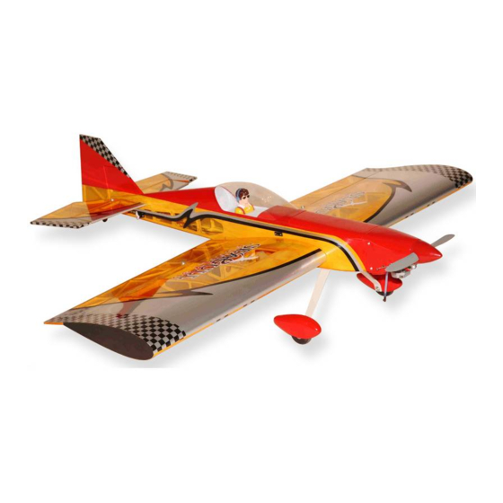
MS:40
ASSEMBLY MANUAL
"Graphics and specifications may change without notice".
Specifications:
Wing span ----------------------------50.4in (128cm).
Wing area -----------------840.1sq.in (54.2sq dm).
Weight ----------------------- 5.1-5.7lbs (2.3-2.6kg).
Length ---------------------------------51.6in (131cm).
Engine --------------- 0.46-0.55cu.in ----2-stroke.
0.72cu.in ---4-stroke.
Radio --------------------4 channels with 6 servos.
Electric conversion: optional
Advertisement
Table of Contents

Related Manuals for Seagull Models Funfly 3D


Summary of Contents for Seagull Models Funfly 3D
- Page 1 MS:40 ASSEMBLY MANUAL “Graphics and specifications may change without notice”. Specifications: Wing span ----------------------------50.4in (128cm). Wing area -----------------840.1sq.in (54.2sq dm). Weight ----------------------- 5.1-5.7lbs (2.3-2.6kg). Length ---------------------------------51.6in (131cm). Engine --------------- 0.46-0.55cu.in ----2-stroke. 0.72cu.in ---4-stroke. Radio --------------------4 channels with 6 servos. Electric conversion: optional...
-
Page 2: Kit Contents
ARTF, yet the design allows the aeroplane to be kept light. You will find that most of the work has been done for you already. The motor mount has been fitted and the hinges are pre-installed. Flying the SEAGULL FUNFLY 3D is simply a joy. -
Page 3: Hinging The Ailerons
www.seagullmodels.com CONTENS.TS HINGING THE AILERONS . Note: The control surfaces, including the Fuselage ailerons, elevators, and rudder, are Left wing panel prehinged with hinges installed, but Right wing panel Tail set (2) the hinges are not glued in place. It Pilot is imperative that you properly Aluminum wing tube... -
Page 4: Hinging The Rudder
Instruction Manual. SEAGULL FUNFLY 3D. 6) Using C/A remover/debonder and a paper towel, remove any excess C/A glue that may have accumulated on the wing or in the aileron hinge area. 7) Repeat this process with the other wing panel, securely hinging the aileron in place. - Page 5 www.seagullmodels.com 2 sets. 3x35mm. Aileron control horn. 2) Position the control horn on the bottom of the aileron. You will see pre-drill hole 3mm for the horn mounting screw on the aileron. INSTALL ELEVATOR CONTROL HORN. Install the elevator control horn using the same method as same as the aileron control horns.
-
Page 6: Engine Mount Installation
Instruction Manual. SEAGULL FUNFLY 3D. Epoxy. Epoxy. Horizontal Elevator. Stabilizer. Rudder Fuselage 18mm 18mm Elevator control horn. Rudder control horn. INSTALL RUDDER CONTROL HORN. ENGINE MOUNT INSTALLATION. Repeat steps to install the rudder control horn as same as steps done for ailerons. -
Page 7: Installing The Stopper Assembly
www.seagullmodels.com Vent tube. Fuel pick up tube. INSTALLING THE STOPPER ASSEMBLY. Fuel fill tube. 1) Using a modeling knife, carefully cut off the rear portion of one of the 3 nylon tubes 3) Carefully bend the second nylon tube leaving 1/2” protruding from the rear of the up at a 45º... - Page 8 Instruction Manual. SEAGULL FUNFLY 3D. 7) Slide the fuel tank into the fuselage. Guide WHEEL AND WHEEL PANTS the lines from the tank through the hole in the INSTALLATION. firewall. 1) Assemble and mounting the landing gear wheels to the wheel pants as shown in the following pictures.
-
Page 9: Installing The Main Landing Gear
www.seagullmodels.com wheel. wheel collar. Washer. nut. Axle. wheel Pant. Landing Gear. wheel Pant. C/A glue. Repeat the process for the other wheel. INSTALLING THE MAIN LANDING GEAR. 1) The blind nuts for securing the landing gear are already mounted inside the fuselage. 2) Using the hardware provided, mount the main landing gear to the fuselage. -
Page 10: Installing The Fuselage Servos
Instruction Manual. SEAGULL FUNFLY 3D. INSTALLING THE FUSELAGE SERVOS. Throttle servo. THROTTLE SERVO ARM INSTALLATION. Install adjustable servo connector in the servo arm as same as picture below: Because the size of servos differ, you may need to adjust the size of the precut open- ing in the mount. -
Page 11: Installing The Switch
www.seagullmodels.com INSTALLING THE SWITCH. Servos. Small weight. Install the switch into the precut hole in the side, in the fuselage. 3/ 32” Hole. Thread. Because the size of servos differ, you may need to adjust the size of the precut open- ing in the mount. -
Page 12: Mounting The Engine
Instruction Manual. SEAGULL FUNFLY 3D. MOUNTING THE ENGINE. 1) Position the engine with the drive washer (110mm) forward of the firewall as shown. Pushrod tube hole. 2) Use a pin drill and 2mm drill bit to drill a small indentation in the mount for the engine mounting screw. - Page 13 www.seagullmodels.com M3x25mm COWLING. 5) Slide the pushrod tube in the firewall and 1) Slide the fiberglass cowl over the en- guide it through the fuel tank mount. Use medium C/A to glue the tube to the firewall and gine and line up the back edge of the cowl with the fuel tank mount.
- Page 14 Instruction Manual. SEAGULL FUNFLY 3D. 3) Install the muffler and muffler extension onto the engine and make the cutout in the Trim and cut. cowl for muffler clearance. Connect the fuel and pressure lines to the carburetor, muffler and fuel filler valve. Secure the cowl to fuse- lage using the M3x10mm screws.
- Page 15 www.seagullmodels.com 2) Attach the electric motor box to the firewall suitable with the cross lines drawn on the electric 4mm. motor box and firewall. Using epoxy and balsa stick to secure the motor box to the firewall. Please see pictures below. Epoxy.
-
Page 16: Installing The Horizontal Stabilizer
Instruction Manual. SEAGULL FUNFLY 3D. The propeller should not touch any part 4) Locate the plywood battery tray to the of the spinner cone. If it does, use a fuselage. sharp modeling knife and carefully trim away the spinner cone where the propeller comes in contact with it. - Page 17 www.seagullmodels.com 4) Install the stabilizer onto the fuselage. 9) When you are sure that everything is Align the centerline drawn on the top and the aligned correctly, mix up a generous amount rear of the stabilizer with the centre of the fu- of 30 Minute Epoxy.
-
Page 18: Hinging The Elevator
Instruction Manual. SEAGULL FUNFLY 3D. 4)Deflect the elevator and completely HINGING THE ELEVATOR. saturate each hinge with thin C/A glue. The elevator front surface should lightly contact 1) Carefully remove the elevator from one the fuselage during this procedure. Ideally, of the fuselage panel. - Page 19 www.seagullmodels.com 5) Turn the fuselage panel over and deflect Pen. the elevator in the opposite direction from the opposite side. Apply thin C/A glue to each hinge, making sure that the C/A penetrates into the elevator and fuselage panel. 6) Using C/A remover/debonder and a paper towel, remove any excess C/A glue that may have accumulated on the fuselage or in the elevator hinge area.
- Page 20 Instruction Manual. SEAGULL FUNFLY 3D. 6) When you are sure that everything is aligned correctly, mix up a generous amount of Flash 30 Minute Epoxy. Apply a thin layer to the mounting slot in the top of the fuselage and to the sides and bottom of the vertical stabilizer mounting area.
- Page 21 www.seagullmodels.com 110mm. Aileron pushrod. M3 clevis. M3 lock nut. M3 lock nut. 140mm. INSTALLATION TAILWHEEL. Elevator pushrod. Rudder pushrod. M2 x 12mm. AILERON PUSHROD HORN INSTALLATION. 1) Locate the pre-drilled hole in the bottom of the rudder. This is the hole for the vertical shaft of the tailwheel assembly.
- Page 22 Instruction Manual. SEAGULL FUNFLY 3D. 2) A scale pilot is included with this ARF. The Seagull Pilot included fitting well to the cockpit. (or you can order others scale pilot figures made by Seagull factory. They are available at Seagull distributors.) 2mm.
- Page 23 www.seagullmodels.com INSTALLING RECEIVER AND BATTERY. 1) Plug the five servo leads and the switch lead into the receiver. Plug the battery pack lead into the switch also. 3 x 10mm. 2) Wrap the receiver and battery pack in the protective foam rubber to protect them from vibration.
-
Page 24: Control Throws
CONTROL THROWS. 2) Check every bolt and every glue joint in the SEAGULL FUNFLY 3D to ensure that Low rate High rate everything is tight and well bonded. Aileron: 1-inch(15 )up. 1 5/8-inch(23 )up.
Need help?
Do you have a question about the Funfly 3D and is the answer not in the manual?
Questions and answers