Table of Contents
Advertisement
"Graphics and specfications may change without notice".
Specifications
Wingspan---------------------------------------- 63 in---------------------------- 160cm.
Wing area------------------------------------- 662.8 sq.in---------------- 42.8 sq.dm.
Approximate flying weight---------------- 6.6-7.5 lbs------------------- 3.0-3.2kg.
Length-------------------------------------------- 45.9 in------------------------ 116.7cm.
Recommended engine size----------- .61-75 cu.in--------------------- 2-stroke.
Radio System required 4 channels with 6 servos.
Flying skill level Intermediate/advanced.
Kit features.
•
Ready-made—minimal assembly & finishing required.
•
Ready-covered covering.
•
Photo-illustrated step-by-step Assembly Manual.
Made in Vietnam.
ASSEMBLY MANUAL
.72 - 1.15 cu.in------------- 4-stroke.
MS: 70
2
Advertisement
Table of Contents

Related Manuals for Seagull Models Extra 300S


Summary of Contents for Seagull Models Extra 300S
-
Page 1: Specifications
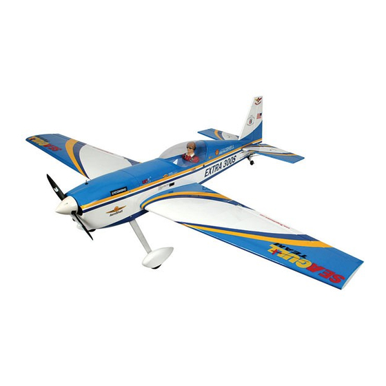
MS: 70 ASSEMBLY MANUAL “Graphics and specfications may change without notice”. Specifications Wingspan---------------------------------------- 63 in---------------------------- 160cm. Wing area------------------------------------- 662.8 sq.in---------------- 42.8 sq.dm. Approximate flying weight---------------- 6.6-7.5 lbs------------------- 3.0-3.2kg. Length-------------------------------------------- 45.9 in------------------------ 116.7cm. Recommended engine size----------- .61-75 cu.in--------------------- 2-stroke. .72 - 1.15 cu.in------------- 4-stroke. Radio System required 4 channels with 6 servos. - Page 2 . Flying the EXTRA 300S is simply a joy. This instruction manual is designed to help you build a great flying aeroplane. Please read this manual thoroughly before starting assembly of your EXTRA 300S. Use the parts listing below to identify all parts.
-
Page 3: Hinging The Ailerons
Hinge. fit and are aligned properly before gluing! This will ensure proper as- sembly as the EXTRA 300S is made 3) Slide the wing panel on the aileron until from natural materials and minor ad- there is only a slight gap. The hinge is now justments may have to be made. -
Page 4: Hinging The Rudder
EXTRA 300S Instruction Manual 5) Turn the wing panel over and deflect the Installing the turnbuckle for tail strut of hori- aileron in the opposite direction from the zontal fin as same as pictures below. opposite side. Apply thin C/A glue to each hinge, making sure that the C/A penetrates into both the aileron and wing panel. - Page 5 www.seagullmodels.com Vent tube. Fuel pick up tube. INSTALLING THE STOPPER ASSEMBLY. Fuel fill tube. 1) Using a modeling knife, carefully cut off the rear portion of one of the 3 nylon tubes Carefully use a lighter or heat gun to leaving 1/2”...
-
Page 6: Fuel Tank Installation
EXTRA 300S Instruction Manual FUEL TANK INSTALLATION. Plastic tape. You should mark which tube is the vent and which is the fuel pickup when you attach fuel tubing to the tubes in the stopper. 2) Follow diagram below for wheel pant Once the tank is installed inside the fuselage, it may be difficult to determine which is which. -
Page 7: Mounting The Engine
www.seagullmodels.com 2) Using the hardware provided, mount (2) Washer. the main landing gear to the fuselage. (2) Wheel Collar. Axle. Nut. 4x20mm. Wheel. Nut. MOUNTING THE ENGINE. 1) Install the pushrod housing through the predrilled hole in the firewall and into the servo compartment. -
Page 8: Cowling Installation
EXTRA 300S Instruction Manual Trim and cut. 4.2mm. Trim and cut. 5) Bolt the engine to the engine mount using the four machine screws. Double check that all the screws are tight before proceeding. 6) Attach the Z-Bend in the pushrod wire to the throttle arm on the carburetor. -
Page 9: Installing The Spinner
www.seagullmodels.com 3) Install the muffler and muffler extension onto the engine and make the cut out in the cowl for muffler clearance. Connect the fuel and pressure lines to the carburetor, muffler and fuel filler valve. Secure the cowl to fuse- lage using the 3x10mm screws (4). -
Page 10: Installing The Switch
EXTRA 300S Instruction Manual INSTALLING THE SWITCH. Install the switch into the precut hole in the Center line. side of fuselage. 2) Using a modeling knife, carefully remove the covering at mounting slot of horizontal sta- bilizer ( both side of fuselage). -
Page 11: Vertical Stabilizer Installation
www.seagullmodels.com When cutting through the covering to re- 2) Slide the vertical stabilizer into the slot move it, cut with only enough pressure in the top of the fuselage. The rear edge of to only cut through the covering itself. Cutting the stabilizer should be flush with the rear edge into the balsa structure may weaken it. -
Page 12: Installing The Aileron Servos
EXTRA 300S Instruction Manual When cutting through the covering to re- INSTALLING THE AILERON SERVOS. move it, cut with only enough pressure to only cut through the covering itself. Cutting Small weight. into the balsa structure may weaken it. 5) Slide the vertical stabilizer back in place. - Page 13 www.seagullmodels.com Wing bottom. drill hole 3.2mm. Secure the servos with the screws pro- vided with your radio system. Wing bottom. Wing bottom. M3 lock nut. M3 control horn. Repeat the procedure for orther wing haft. M3 nut. AILERON CONTROL HORN INSTALLATION 2 sets.
- Page 14 EXTRA 300S Instruction Manual 3) Install the rudder control horn using the same method as with the elevator control horns. Left side. Elevator control horn. M2 lock nut. Rudder control horn. Repeat the procedure for the other wing. ELEVATOR - RUDDER CONTROL HORN INSTALLATION.
- Page 15 www.seagullmodels.com Rudder pushrod. plastic clip. Elevator pushrod. Elevator pushrod. Elevator. Plastic trap. Rudder. Throttle. Elevator. MOUNTING THE CONTROL CLASP. INSTALLING TAIL STRUT SYSTEM. See pictures below. The tail strut system assembly follow pictures below. Control clasp. 2 Screws. 2x20mm Machine screws. Plastic trap.
- Page 16 EXTRA 300S Instruction Manual wing bolt. Battery. Receiver. Antenna. BALANCING. ATTACHMENT WING-FUSELAGE. 1) It is critical that your airplane be bal- Attach the aluminium tube into fuselage. anced correctly. Improper balance will cause your plane to lose control and crash. The cen- 4.5cm...
-
Page 17: Control Throws
Ailerons low rate -3/8” up -3/8” down Elevator low rate -3/16” up - 3/16” down 2) Check every bolt and every glue joint in the EXTRA 300S to ensure that everything Ailerons high rate - 7/8” up -7/8” down is tight and well bonded. - Page 18 EXTRA 300S Instruction Manual FOR USA MARKET ONLYLY. Warranty Period: Exclusive Warranty- Horizon Hobby, Inc., (Horizon) warranties that the Products purchased (the “Product”) will be free from defects in materials and workmanship at the date of purchase by the Purchaser.
- Page 19 www.seagullmodels.com Warranty Inspection and Repairs To receive warranty service, you must include your original sales receipt verifying the proof-of-purchase date. Provided warranty conditions have been met, your Product will be repaired or replaced free of charge. Repair or replacement decisions are at the sole discretion of Horizon Hobby. Non-Warranty Repairs Should your repair not be covered by warranty the repair will be completed and payment will be required without notification or estimate of the expense unless the expense exceeds 50% of the retail purchase cost.
Need help?
Do you have a question about the Extra 300S and is the answer not in the manual?
Questions and answers