Table of Contents
Advertisement
Quick Links
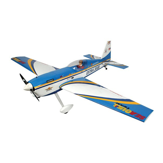
Hand-made Almost Ready to Fly R/C Model Aircraft
Kit features
•
Ready-made—minimal assembly & finishing required.
•
Ready-covered—including decals, trim & covering.
•
Factory-installed pushrods.
•
Factory-installed metal engine mount.
•
Factory-pinned & glued control surface hinges for ultimate safety.
•
Comprehensive hardware pack including wheels, tank, spats,undercarriage& spinner.
•
Photo-illustrated step-by-step Assembly Manual.
•This aicraft has been designed for intermediate level flyers. First time pilot should be a
experienced flyer
( proficient pilot
•This aicraft is desgined to be powered
Installation of engines other it could to lead a seious accident or damage t property.
Made in Vietnam
ASSEMBLY MANUAL
WARNING
).
a 2 stroke .46 engine or a 4 stroke .53
engine.
Advertisement
Table of Contents

Related Manuals for Seagull Models Extra 300S


Summary of Contents for Seagull Models Extra 300S
- Page 1 Hand-made Almost Ready to Fly R/C Model Aircraft ASSEMBLY MANUAL Kit features • Ready-made—minimal assembly & finishing required. • Ready-covered—including decals, trim & covering. • Factory-installed pushrods. • Factory-installed metal engine mount. • Factory-pinned & glued control surface hinges for ultimate safety. •...
-
Page 2: Instruction Manual
Flying the EXTRA 300S is simply a joy. This instruction manual is designed to help you build a great flying aeroplane. Please read this manual thoroughly before starting assembly of your EXTRA 300S . Use the parts listing below to identify all parts. - Page 3 This will ensure proper as- sembly as the EXTRA 300S is made from natural materials and minor ad- justments may have to be made. The paint and plastic parts used in this kit are fuel proof.
-
Page 4: Wing Assembly
EXTRA 300S Instruction Manual the top and bottom as well as the sides of the WING ASSEMBLY dihedral brace. Use enough epoxy to fill any NOTE: We highly recommend using 30 gaps. minute epoxy as it is stronger and provides more working time, allowing ! 4. -
Page 5: Installing The Aileron Servos
EXTRA 300S INSTRUCTION MANUAL INSTALLING THE AILERON SERVOS. Use a small weight (Weighted fuel pick-up) and thread to feed the servo connector through the wing as shown. Small weight Servo (2pcs). Small weight. Thread Thread. ! 1) Remove servo tray from the each panel of wing. -
Page 6: Installing The Aileron Linkage
EXTRA 300S Instruction Manual INSTALLING THE AILERON LINKAGE Thread ! 1) Using a ruler & pen to draw a straight line as below picture. Servo electric wire Servo arm ! 3) Install the aileron servo tray into the servo mount. - Page 7 EXTRA 300S INSTRUCTION MANUAL 3) Position the aileron horn on the bottom side of aileron. The clevis attachment holes should be positioned over the hinge line as shown below. clevis Control Horn Aileron Torque rod Mounting Screws Mounting Plate 4) Using a 1mm drill bit and the control horns as a guide, drill the mounting holes through the aileron halves.
-
Page 8: Installing The Stopper Assembly
EXTRA 300S Instruction Manual ! 5) With the stopper assembly in place, FUEL TANK the weighted pickup should rest away from the rear of the tank and move freely inside the PARTS REQUIRED tank. The top of the vent tube should rest just... -
Page 9: Mounting The Engine
EXTRA 300S INSTRUCTION MANUAL ! 5) Attach the Z-Bend in the pushrod wire to Vent tube the throttle arm on the carburetor. You will need to remove the throttle arm from the car- buretor to be able to attach the Z-bend. When complete, reattach the throttle arm to the car- buretor. -
Page 10: Installing The Main Landing Gear
EXTRA 300S Instruction Manual Landing gear ! ! ! ! ! 2) A drop of C/A glue on the wheel collar screws will help keep them from coming lose during operation. Repeat the process for the other wheel. INSTALLING THE MAIN LANDING GEAR ! ! ! ! ! 1) The blind nuts are already mounted in- side the fuselage. - Page 11 EXTRA 300S INSTRUCTION MANUAL Because of the diameter of the cowl, it may be necessary to use a needle valve ! ! ! ! ! 3) Using the hardware provided, mount extension for the high speed needle valve. the main landing gear to the fuselage.
-
Page 12: Aligning The Horizontal Stabilizer
EXTRA 300S Instruction Manual ALIGNING THE HORIZONTAL STABILIZER ! 1) Using a ruler and a pen, locate the centerline of the horizontal stabilizer, at the trailing edge, and place a mark. Use a tri- angle and extend this mark, from back to front, across the top of the stabilizer. - Page 13 EXTRA 300S INSTRUCTION MANUAL ! 4) Remove the stabilizer. Using the lines you just drew as a guide, carefully remove the covering from between them using a model- alumium plate ing knife. Remove covering 3MM x 12MM Tail gear washer...
-
Page 14: Vertical Stabilizer Installation
EXTRA 300S Instruction Manual VERTICAL STABILIZER INSTALLATION Hinge ! 1) Using a modeling knife, remove the covering from over the precut hinge slot cut into the lower rear portion of the fuselage. This ! 7) When you are sure that everything is slot accepts the lower rudder hinge. - Page 15 EXTRA 300S INSTRUCTION MANUAL ! 6) When you are sure that everything is ! 3) While holding the vertical stabilizer aligned correctly, mix up a generous amount firmly in place, use a pen and draw a line on of Flash 30 Minute Epoxy. Apply a thin layer to...
-
Page 16: Installing The Fuselage Servos
EXTRA 300S Instruction Manual ELEVATOR - RUDDER PUSHROD INSTALLATION. Control Horn Rudder pushrod Mounting Screws Mounting Plate 3) Using a 1.5mm drill bit and the control horns as a guide, drill the mounting holes Elevator pushrod through the elevator halves. - Page 17 EXTRA 300S INSTRUCTION MANUAL ! 2) Using a 3/32” drill bit, drill a hole ) Install adjustable servo connector in through the side of the fuselage, opposite the the servo arm. muffler, even with the switch. ! 3) Make a push-pull lever out of scrap wire.
-
Page 18: Installing The Receiver And Battery
EXTRA 300S Instruction Manual INSTALLING THE RECEIVER AND BATTERY ! ! ! ! ! 1) Plug the five servo leads and the switch lead into the receiver. Plug the battery pack lead into the switch also. ! ! ! ! ! 2) Wrap the receiver and battery pack in... -
Page 19: Flight Preparation
! ! ! ! ! 1) We highly recommend setting up the the elevator stick. The elevator halves should EXTRA 300S using the control throws listed move up. If it they do not, flip the servo re- at right. We have listed control throws for both versing switch on your transmitter to change initial test/sport flying and aerobatic flying. -
Page 20: Preflight Check
2) Check every bolt and every glue joint in the EXTRA 300S to ensure that everything is tight and well bonded. 3) Double check the balance of the air- plane. Do this with the fuel tank empty. -
Page 21: Assembly Manual
Hand-made Almost Ready to Fly R/C Model Aircraft ASSEMBLY MANUAL Kit features • Ready-made—minimal assembly & finishing required. • Ready-covered—including decals, trim & covering. • Factory-installed pushrods. • Factory-installed metal engine mount. • Factory-pinned & glued control surface hinges for ultimate safety. •...
Need help?
Do you have a question about the Extra 300S and is the answer not in the manual?
Questions and answers