Table of Contents
Advertisement
Quick Links
A S S E M B L Y
A S S E M B L Y
A S S E M B L Y
A S S E M B L Y
A S S E M B L Y
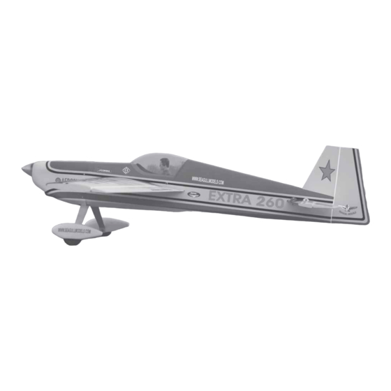
"Graphics and Specfications may change without notice".
Specifications
Wingspan---------------------------------------- 70.9 in---------------------------- 182cm.
Wing area---------------------------------------- 967sq.in-------------------- 62.4 sq.dm.
Approximate flying weight------------------ 12.8-13lbs------------------- 4.8-5.8kg.
Length-------------------------------------------- 64 in----------------------------- 163.5cm.
Recommended engine size--------------- 1.60 cu.in---------------------- 2-stroke.
Radio System required 6 channels with 6 digital servos.
Flying skill level Intermediate/advanced.
Kit features.
•
Ready-made—minimal assembly & finishing required.
•
Ready-covered covering.
•
Photo-illustrated step-by-step Assembly Manual.
Made in Vietnam.
M A N U A L
M A N U A L
M A N U A L
M A N U A L
M A N U A L
1.80 cu.in---------------------- 4-stroke.
MS:58
Advertisement
Table of Contents

Related Manuals for Seagull Models Extra 260


Summary of Contents for Seagull Models Extra 260
- Page 1 MS:58 A S S E M B L Y A S S E M B L Y A S S E M B L Y A S S E M B L Y A S S E M B L Y M A N U A L M A N U A L M A N U A L...
-
Page 2: Instruction Manual
ARTF , yet the design allows the aeroplane to be kept light. You will find that most of the work has been done for you already.Flying the EXTRA 260 is simply a joy. This instruction manual is designed to help you build a great flying aeroplane. Please read this manual thoroughly before starting assembly of your EXTRA 260. -
Page 3: Hinging The Ailerons
Hinge. fit and are aligned properly before gluing! This will ensure proper as- sembly as the EXTRA 260 is made from natural materials and minor ad- 3) Slide the aileron on the wing panel until justments may have to be made. -
Page 4: Installing The Aileron Servos
EXTRA 260. Instruction Manual. 5) Turn the wing panel over and deflect the aileron in the opposite direction from the opposite side. Apply thin C/A glue to each hinge, making sure that the C/A penetrates into both the aileron and wing panel. -
Page 5: Engine Mount
www.seagullmodels.com Attach the thread to the servo lead and carefully thread it though the wing. Once you Plastic tape. have thread the lead throught the wing, remove the string so it can use for the other servo lead. Tape the servo lead to the wing to prevent it from falling back into the wing. - Page 6 EXTRA 260. Instruction Manual. FUEL TANK. Vent tube. Fuel pick up tube. INSTALLING THE STOPPER ASSEMBLY. 1) Using a modeling knife, carefully cut off the rear portion of one of the 3 nylon tubes Fuel fill tube. leaving 1/2” protruding from the rear of the stopper.
- Page 7 www.seagullmodels.com You should mark which tube is the vent and which is the fuel pick up when you attach fuel tubing to the tubes in the stopper. Once the tank is installed inside the fuselage, it may be difficult to determine which is which. 2) Follow diagram below for wheel pant installation: Plywood Washer.
-
Page 8: Installing The Main Landing Gear
EXTRA 260. Instruction Manual. Landing gear. 4) A drop of Thread locker glue on the wheel collar screws will help keep them from coming lose during operation. Repeat the process for the other wheel. Plywood Washer. INSTALLING THE MAIN LANDING GEAR. -
Page 9: Elevator Servo Installation
www.seagullmodels.com Throttle servo. Throttle servo. Rudder servo. Rudder servo. ELEVATOR SERVO INSTALLATION. Locate and cut out the covering film Engine - 4 stroke: from the servo holes in both sides of fuselage. Left side. Servo tray. Remove covering. 2) Install the rubber grommets and brass collets onto the elevator servo. -
Page 10: Mounting The Engine
EXTRA 260. Instruction Manual. MOUNTING THE ENGINE. Engine - 2 stroke: 1) Install the pushrod housing through the predrilled hole in the firewall and into the servo compartment. The pushrod housing should protrude 1/4" out past the front of the firewall. -
Page 11: Installing The Switch
www.seagullmodels.com 1) Slide the fiberglass cowl over the en- gine and line up the back edge of the cowl with the marks you made on the fuselage then trim 1.5mm wire and cut. (needle valve). Slide the cowl back over the engine and secure it in place using four 3 x 10mm 3x10mm. - Page 12 EXTRA 260. Instruction Manual. INSTALLING HORIZONTAL FIN. 1) Remove the covering at the rear tail root of horizontal fin as picture shown below. Switch. THROTTLE SERVO ARM INSTALLATION. 2) Sand the aluminium tube using ) Install adjustable servo connector in sandpaper.
-
Page 13: Vertical Stabilizer Installation
www.seagullmodels.com 2) Slide the vertical stabilizer into the slot 5) Bolt the horizontal fin to the fuselage in the top of the fuselage. The rear edge of side using the 4 machine screws (3x10mm). the stabilizer should be flush with the rear edge Double cheek that all the screws are tight before proceeding. - Page 14 EXTRA 260. Instruction Manual. AILERON CONTROL HORN INSTALLATION. When cutting through the covering to re- move it, cut with only enough pressure to only cut through the covering itself. Cutting into the balsa structure may weaken it. 5) Slide the vertical stabilizer back in place.
- Page 15 www.seagullmodels.com Repeat the procedure for orther wing. ELEVATOR CONTROL HORN INSTALLATION. 1) Elevator control horn: Using the same tectniques used aileron control horn. See picture below. Horizontal fin. Elevator. Rudder control horn. ELEVATOR PUSHROD INSTALLATION. Elevator pushrods assembly follow pictures below.
- Page 16 EXTRA 260. Instruction Manual. Repeat the procedure for wing panel as same as elevator pushrod. Pushrod L= 104mm. Metal Levis. 2) With the radio on, check the operation of the rudder. Adjust the cables so when the rudder servo is centered, the rudder is centered as well.
-
Page 17: Mounting The Tail Wheel
www.seagullmodels.com MOUNTING THE TAIL WHEEL. INSTALLING THE BATTERY-RECEIVER. See picture below 1) Plug the servo leads and the switch lead into the receiver. Plug the battery pack lead into the switch also. 2) Wrap the receiver and battery pack in the protective foam rubber to protect them from vibration. -
Page 18: Control Throws
8.5-9.5cm. CONTROL THROWS. Wing bolt. We highly recommend setting up the EXTRA 260 using the control throws listed at right. We have listed control throws for both Low Rate (initial test flying/sport flying) and High Rate (aerobatic flying). Turn on the radio system, and with the... - Page 19 Rudder: 2 1/2” right and left flying. AEROBATIC FLYING 2) Check every bolt and every glue joint in the EXTRA 260 to ensure that everything is Ailerons: 1” up 7/8” down tight and well bonded. Elevator: 1 1/4”...
- Page 20 EXTRA 260. Instruction Manual. FOR USA MARKET ONLYLY. Warranty Period: Exclusive Warranty- Horizon Hobby, Inc., (Horizon) warranties that the Products purchased (the “Product”) will be free from defects in materials and workmanship at the date of purchase by the Purchaser.
- Page 21 www.seagullmodels.com Non-Warranty Repairs Should your repair not be covered by warranty the repair will be completed and payment will be required without notification or estimate of the expense unless the expense exceeds 50% of the retail purchase cost. By submitting the item for repair you are agreeing to payment of the repair without notification. Repair estimates are available upon request.
Need help?
Do you have a question about the Extra 260 and is the answer not in the manual?
Questions and answers