Table of Contents
Advertisement
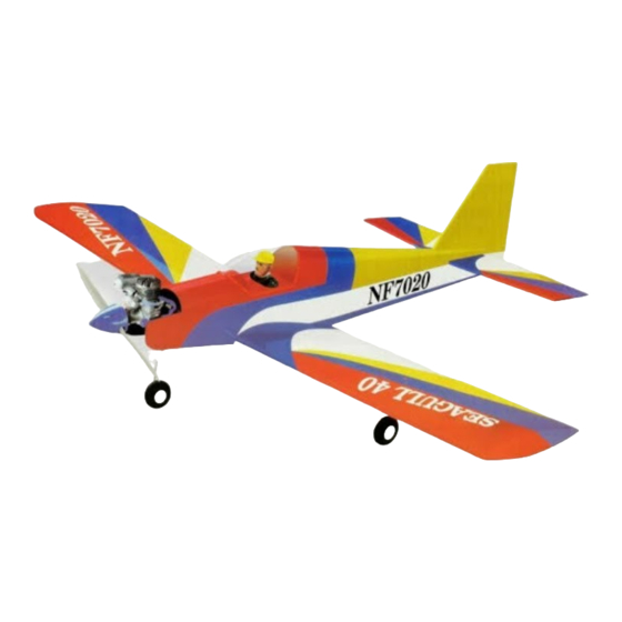
Hand-made Almost Ready to Fly R/C Model Aircraft
"Graphics and specfications may change without notice".
Specifications
Wingspan ------------------------------------------ 60 in/ 153cm.
Wing area ------------------------------------ 620 sq.in/ 40dm
Length -------------------------------------------- 45 in/ 113.7cm.
Approximate flying weight --------- 5.5 - 6.2 lbs/ 2.5-2.8kg.
Recommended engine size - 0.40 -- 0.46 cu. in 2-stroke.
Recommended R/C ------------------- 4 channel minimum.
Flying skill level ----------------------------- Low wing Trainer.
Kit features.
•
Ready-made-minimal assembly & finishing required.
•
Factory-installed pushrod.
•
Photo-illustrated step-by-step Assembly Manual.
SEAGULL 40
LOW WING TRAINER
ASSEMBLY MANUAL
2
.
0.52 cu. in 4-stroke.
Additional items required.
Engine.
4 Channel or greater Radio Control system.
Glues.
Tools.
Starting Equipment.
Made in Vietnam.
MS:10
Advertisement
Table of Contents

Subscribe to Our Youtube Channel
Related Manuals for Seagull Models SEAGULL 40


Summary of Contents for Seagull Models SEAGULL 40
- Page 1 SEAGULL 40 LOW WING TRAINER Hand-made Almost Ready to Fly R/C Model Aircraft MS:10 ASSEMBLY MANUAL “Graphics and specfications may change without notice”. Specifications Additional items required. Wingspan ------------------------------------------ 60 in/ 153cm. Engine. Wing area ------------------------------------ 620 sq.in/ 40dm 4 Channel or greater Radio Control system.
-
Page 2: Wing Assembly
ARTF , yet the design allows the aeroplane to be kept light. You will find that most of the work has been done for you already. Flying the SEAGULL 40 is simply a joy. -
Page 3: Installing The Aileron Servos
www.seagullmodels.com 2) Remove the brace when satisfied with 3) Peel off the backing from the self adhe- its fit ineach wing half. Coat both sides of one sive covering strip. Apply the strip to the centre half of the dihedral brace with 30 minute epoxy. section of the wing starting from the bottom Next, pour some epoxy into the dihedral box in trailing edge. - Page 4 SEAGULL 40 Instruction Manual. LOW WING TRAINER. String. Small weight. Thread. Small weight. Wing bottom. Thread. 4) Tape the servo lead to the wing to pre- vent it from falling back into the wing. Plastic tape. 3) Attach servo lead to the aileron servo.
-
Page 5: Aileron Linkage
www.seagullmodels.com Repeat the procedure for the other wing half. Control Horn. AILERON LINKAGE. 1) Using a ruler & pen to draw a straight line as below picture. Mounting Screws. Mounting Plate. 4) Using a 1mm drill bit and the control horns as a guide, drill the mounting holes through the aileron halves. -
Page 6: Installing The Main Gear Wires
SEAGULL 40 Instruction Manual. LOW WING TRAINER. 3x10mm. Cut. 1) Using a modeling knife, remove the 8) Make a 90-degree bend at the mark covering from over the two main gear mount- and cut off the excess wire leaving 10mm past ing slots located in the bottom of the wing. -
Page 7: Installing The Stopper Assembly
www.seagullmodels.com INSTALLING THE STOPPER ASSEMBLY. Pen. 1) Using a modeling knife, carefully cut off the rear portion of one of the two nylon tubes leaving 1/2” protruding from the rear of the stopper. This will be the fuel pick up tube. 2) Using a modeling knife, cut one length of silicon fuel line (not included) to 2-1/4”... -
Page 8: Mounting The Engine
SEAGULL 40 Instruction Manual. LOW WING TRAINER. 5) Test fit the stopper assembly into the tank. It may be necessary to remove some of the flashing around the tank opening using a modeling knife. If flashing is present, make sure none falls into the tank. -
Page 9: Nose Gear Installation
www.seagullmodels.com 112mm. NOSE GEAR INSTALLATION. 2.5mm. 3x25mm. 5) Bolt the engine to the engine mount using the four machine screws. Double check that all the screws are tight before proceeding. 6) Attach the Z-Bend in the pushrod wire to the throttle arm on the carburetor. Installing steering arm as below. -
Page 10: Installing The Switch
SEAGULL 40 Instruction Manual. LOW WING TRAINER. Install the pushrod wire as shown. Adjustable Connector. INSTALLING THE SWITCH. 1) Install the switch into the precut hole INSTALLING THE SPINNER. in the fuselage side. Use the two screws pro- vided with the switch to secure it in place. -
Page 11: Horizontal Stabilizer
www.seagullmodels.com Secure the servos with the screws pro- vided from your radio system. 2) Position the servos into the servo tray with the output shafts orientated as shown below. Drill 1/16” pilot holes through the tray for each of the mounting screws. Throttle. -
Page 12: Vertical Stabilizer Installation
SEAGULL 40 Instruction Manual. LOW WING TRAINER. 2) Slide the vertical stabilizer into the slot 7) When you are sure that everything is in the top of the fuselage. The rear edge of aligned correctly, mix up a generous amount the stabilizer should be flush with the rear edge of 30 Minute Epoxy. -
Page 13: Control Horn Installation
www.seagullmodels.com When cutting through the covering to re- move it, cut with only enough pressure to only cut through the covering itself. Cutting into the balsa structure may weaken it. 5) Slide the vertical stabilizer back in place. Using a triangle, check to ensure that the vertical stabilizer is aligned 90º... -
Page 14: Installing The Receiver And Battery
SEAGULL 40 Instruction Manual. LOW WING TRAINER. ELEVATOR-RUDDER PUSHROD Antenna wire. INSTALLATION. Elevator pushrod. Control horn. Rudder pushrod. Clevis. Antenna. Battery. Tie wrap. Adjustable Servo connector. Servo arm. Receiver. (1 PCS). (2 PCS). ATTACHMENT WING - FUSELAGE. Thread locker glue. -
Page 15: Flight Preparation
We highly recommend setting up the move up. If it they do not, flip the servo re- SEAGULL 40 using the control throws listed versing switch on your transmitter to change at right. We have listed control throws for both the direction. -
Page 16: Preflight Check
6) Check to ensure the control surfaces 2) Check every bolt and every glue joint are moving the proper amount for both low in the SEAGULL 40 to ensure that everything and high rate settings. is tight and well bonded.
Need help?
Do you have a question about the SEAGULL 40 and is the answer not in the manual?
Questions and answers