Table of Contents
Advertisement
Quick Links
WWW.SEAGULLMODELS.COM
A S S E M B L Y M A N U A L
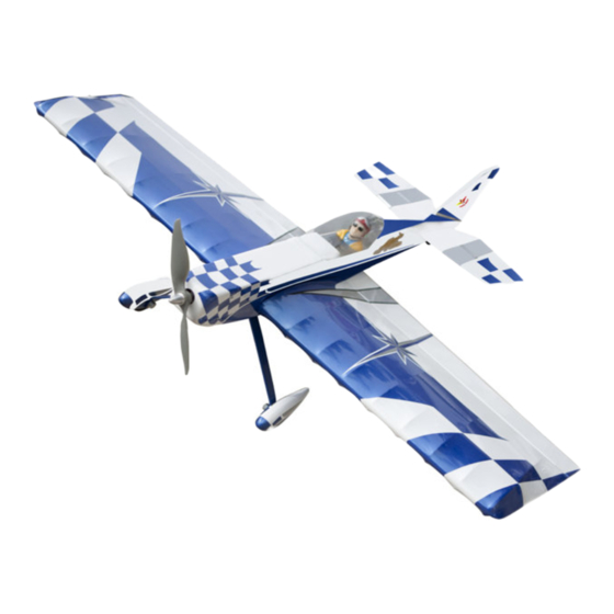
MAGIC STAR 3D ELECTRIC POWER
wingspan 39"
Code: SEAX157
" Graphics and specifications may change without notice " .
Specifications:
Wingspan---------------39 in (99.1 cm).
Wing area---------------432.5 sq.in (27.9 sq.dm).
Weight-------------------1.5-1.9 lbs (0.7-0.85 kg).
Length-------------------33.8 in (85.8 cm).
Motor size---------------450-180 size brushless
----------------------------30-amp brushless ESC
Radio---------------------4 channels with 4 sub -micro servos.
www.seagullmodels.com
1
Advertisement
Table of Contents

Related Manuals for Seagull Models Magic Star 3D EP


Summary of Contents for Seagull Models Magic Star 3D EP
- Page 1 WWW.SEAGULLMODELS.COM A S S E M B L Y M A N U A L MAGIC STAR 3D ELECTRIC POWER wingspan 39” Code: SEAX157 “ Graphics and specifications may change without notice “ . Specifications: Wingspan---------------39 in (99.1 cm). Wing area---------------432.5 sq.in (27.9 sq.dm). Weight-------------------1.5-1.9 lbs (0.7-0.85 kg).
-
Page 2: Kit Contents
The motor mount has been fit- ted and the hinges are pre-installed. Flying the MAGIC STAR 3D EP is simply a joy. This instruction manual is designed to help you build a great flying aeroplane. Please read this manual throughly before starting assembly of your MAGIC STAR 3D EP . -
Page 3: Hinging The Aileron
WWW.SEAGULLMODELS.COM KIT CONTENTS. HINGING THE AILERON. SEAX157 MAGIC STAR 3D EP Note : The control surfaces, including the ai- lerons, elevators, and rudder, are prehinged SEAX15701 Fuselage with hinges installed, but the hinges are not SEAX15702 Wing set glued in place. It is imperative that you prop-... - Page 4 Instruction Manual. MAGIC STAR 3D EP 4) Deflect the aileron and completely satu- 7) Repeat this process with the other wing rate each hinge with thin C/A glue. The ailer- panel, securely hinging the aileron in place. ons front surface should lightly contact the wing during this procedure.
-
Page 5: Installing The Aileron Servos
WWW.SEAGULLMODELS.COM Epoxy. Aileron control horn. INSTALLING THE AILERON SERVOS. 3) A string has been provided in the wing to pull the aileron lead through to the wing root. Remove the string from the wing at the servo location and use the tape to attach it to the servo extension lead. - Page 6 Instruction Manual. MAGIC STAR 3D EP CA glue. 2) Pass the Z-bend pushrod through the hole of the control horn. 3) The pushrod wire will pass through the hole in the micro screw-lock connec- tor. Use side cutters to trim the pushrod so it is past the connector as shown.
- Page 7 WWW.SEAGULLMODELS.COM Repeat steps to install the remaining ai- leron control horn and pushrod. C/A glue. INSTALLING THE MAIN LANDING GEAR TO FUSELAGE. M3x15mm WHEELS AND WHEEL PANTS. 1) Locate the items neccessary to install 1) The blind nuts for securing the land- 2) Follow diagram below for wheel pant ing gear are already mounted inside the installation:...
- Page 8 Instruction Manual. MAGIC STAR 3D EP Wheel collar. Axle. Washer. Wheel. Wheel collar. Wheel. Washer. Axle. nut.-- Wheel Pant. Repeat steps to install remaining wheel C/A glue. Lite-Plywood pants to the landing gear. block. ELECTRIC POWER CONVERSION. 1) Locate the items neccessary to install...
- Page 9 WWW.SEAGULLMODELS.COM Blind nut. 4) Attach the motor to the front of the 3) Attach the motor to the front of the electric motor box using four 4mm blind electric motor box using four 4mm blind nut, four M3x10mm hex head bolts to se- nut, four M3x10mm hex head bolts to se- cure the motor.
- Page 10 Instruction Manual. MAGIC STAR 3D EP 5) Attach the speed control to the side of COWLING. the motor box using hook and loop tape. Connect the appropriate leads from the 1) Slide the fiberglass cowl over the en- speed control to the motor. Make sure the...
-
Page 11: Installing The Propeller
WWW.SEAGULLMODELS.COM 2) While keeping the back edge of the cowl 3) Install the muffler and muffler extension flush with the marks, align the front of the onto the engine and make the cutout in the cowl with the crankshaft of the engine. The cowl for muffler clearance. -
Page 12: Stabilizer Installation
Instruction Manual. MAGIC STAR 3D EP STABILIZER INSTALLATION. 1) Using a ruler and a pen, locate the cen- terline of the horizontal stabilizer, at the trailing edge, and place a mark. Use a tri- angle and extend this mark, from back to front, across the top of the stabilizer. -
Page 13: Vertical Fin Installation
WWW.SEAGULLMODELS.COM 7) Fit the joiner wire into the elevators. Check to make sure the elevators are in alignment with each other by placing the assembly on a flat surface. It may be nec- essary to bend the joiner wire slightly to align both elevator halves. -
Page 14: Rudder And Elevator Installation
Instruction Manual. MAGIC STAR 3D EP Hold the stabilizer in place with T-pins or masking tape and remove any excess epoxy using a paper towel and rubbing alcohol. Al- low the epoxy to fully cure before proceed- ing. Remove the covering... - Page 15 WWW.SEAGULLMODELS.COM 2) Place a T-pin in the center of four CA hinges. Insert the hinges into the elevator as shown. The T-pin will rest on the edge of the bevel of the control surface. Prepare both el- evators at this time. 5) Remove the T-pins from hinges.
-
Page 16: Rudder And Elevator Servo Installation
Instruction Manual. MAGIC STAR 3D EP 7) Break in the hinges by working the stabi- lizer up and down a number of times. This will reduce the initial load on the servo when the servo is connected for the first time. - Page 17 WWW.SEAGULLMODELS.COM CA glue. Elevator control horn. 3) Pass the Z-bend in the elevator push- rod through the hole of the control horn. 2) Locate position elevator control horn. Then, apply 2-3 drops of epoxy to the 4) Slide the pushrod into the hole in the backplate where it contacts control horn pushrod connector.
- Page 18 Instruction Manual. MAGIC STAR 3D EP If you are going to install a pilot figure, Repeat steps to install the rudder servo. please use a sanding bar to sand the base of the figure so that it is flat. 3) Position the pilot figure on the canopy floor as show.
-
Page 19: Wing Installation
WWW.SEAGULLMODELS.COM 2) If all the decals are not precut, please use scissors or a sharp hobby knife to cut the decals from the sheet. Please be cer- tain the model is clean and free from oily fingerprints and dust. Position decal on the model where desired, using the pho- tos on the box and aid in their location. -
Page 20: Control Throws
Instruction Manual. MAGIC STAR 3D EP 4) Do not turn plane upside down. Only low wing models should be turned up- sidedown for balancing. Remove this paragraph, it is not intended for use in 89 mm the instructions. it is a note for you.High Wing models must be balanced upright. - Page 21 WWW.SEAGULLMODELS.COM...
-
Page 22: Flight Preparation
Instruction Manual. MAGIC STAR 3D EP FLIGHT PREPARATION. PREFLIGHT CHECK. Check the operation and direction 1) Completely charge your trans- of the elevator, rudder, ailerons and mitter and receiver batteries before throttle. your first day of flying. 2) Check every bolt and every glue...
Need help?
Do you have a question about the Magic Star 3D EP and is the answer not in the manual?
Questions and answers