Juniper EX9214 Hardware Manual
Ex series
Hide thumbs
Also See for EX9214:
- Hardware manual (350 pages) ,
- Quick start manual (13 pages) ,
- Hardware manual (385 pages)

Related Manuals for Juniper EX9214


Summary of Contents for Juniper EX9214
- Page 1 EX9214 Switch Hardware Guide Modified: 2017-07-17 Copyright © 2017, Juniper Networks, Inc.
- Page 2 END USER LICENSE AGREEMENT The Juniper Networks product that is the subject of this technical documentation consists of (or is intended for use with) Juniper Networks software. Use of such software is subject to the terms and conditions of the End User License Agreement (“EULA”) posted at http://www.juniper.net/support/eula.html.
-
Page 3: Table Of Contents
EX9214 Switch Hardware Overview ........ - Page 4 AC Power Supply Configurations ........47 AC Power Supply LEDs in an EX9214 Switch ......47 DC Power Supply in an EX9214 Switch .
- Page 5 Preparation Overview ..........83 Site Preparation Checklist for an EX9214 Switch ......83 Environmental Requirements and Specifications for EX Series Switches .
- Page 6 Connecting Earth Ground to an EX Series Switch ..... 152 Connecting AC Power to an EX9214 Switch ......154 Powering On an AC-Powered EX9200 Switch .
- Page 7 Removing an AC Power Supply from an EX9214 Switch ....191 Installing a DC Power Supply in an EX9214 Switch ......193 Removing a DC Power Supply from an EX9214 Switch .
- Page 8 Replacing Cable Management Bracket ......247 Installing the Cable Management Bracket in an EX9214 Switch ... . . 247 Removing the Cable Management Bracket from an EX9214 Switch .
- Page 9 FCC Part 15 Statement ......... . 346 Copyright © 2017, Juniper Networks, Inc.
- Page 10 Nonregulatory Environmental Standards ......347 Compliance Statements for Acoustic Noise for EX Series Switches ..348 Copyright © 2017, Juniper Networks, Inc.
- Page 11 Figure 13: Midplane in an EX9214 Switch ....... . .
- Page 12 Preparation Overview ..........83 Figure 37: Airflow Through an EX9214 Switch ......92 Figure 38: Clearance Requirements for Airflow and Hardware Maintenance for an EX9214 Switch with AC Power Supplies .
- Page 13 Figure 59: Installing a Fan Tray in an EX9208 Switch ..... . 184 Figure 60: Installing the Upper Fan Tray in an EX9214 Switch ....185 Figure 61: Removing a Fan Tray from an EX9200 Switch .
- Page 14 Components ........... . 263 Figure 93: Location of the Serial Number ID Label on EX9214 Switch Chassis . . 267 Figure 94: Location of the Serial Number ID Label on an AC Power Supply .
- Page 15 Table 3: Line Cards for EX9214 Switches ........
- Page 16 Table 44: AC Power System Specifications ......97 Table 45: AC Power Cord Specifications for an EX9214 Switch ....97 Table 46: DC Power Supply Specifications for an EX9214 Switch .
- Page 17 Table 67: Viewing System Log Messages ....... 295 Copyright © 2017, Juniper Networks, Inc.
- Page 18 EX9214 Switch Hardware Guide xviii Copyright © 2017, Juniper Networks, Inc.
-
Page 19: About The Documentation
® To obtain the most current version of all Juniper Networks technical documentation, see the product documentation page on the Juniper Networks website at http://www.juniper.net/techpubs/ If the information in the latest release notes differs from the information in the documentation, follow the product Release Notes. -
Page 20: Table 1: Notice Icons
RFC 1997, BGP Communities Attribute Italic text like this Represents variables (options for which Configure the machine’s domain name: you substitute a value) in commands or [edit] configuration statements. root@# set system domain-name domain-name Copyright © 2017, Juniper Networks, Inc. -
Page 21: Documentation Feedback
We encourage you to provide feedback, comments, and suggestions so that we can improve the documentation. You can provide feedback by using either of the following methods: Online feedback rating system—On any page of the Juniper Networks TechLibrary site , simply click the stars to rate the content, http://www.juniper.net/techpubs/index.html and use the pop-up form to provide us with information about your experience. -
Page 22: Requesting Technical Support
7 days a week, 365 days a year. Self-Help Online Tools and Resources For quick and easy problem resolution, Juniper Networks has designed an online self-service portal called the Customer Support Center (CSC) that provides you with the following features: Find CSC offerings: http://www.juniper.net/customers/support/... - Page 23 About the Documentation For international or direct-dial options in countries without toll-free numbers, see http://www.juniper.net/support/requesting-support.html Copyright © 2017, Juniper Networks, Inc. xxiii...
- Page 24 EX9214 Switch Hardware Guide xxiv Copyright © 2017, Juniper Networks, Inc.
-
Page 25: Overview
PART 1 Overview Switch Overview on page 3 Chassis Components and Descriptions on page 15 Cooling System and Airflow on page 43 Power Supplies on page 45 Line Cards on page 55 Copyright © 2017, Juniper Networks, Inc. - Page 26 EX9214 Switch Hardware Guide Copyright © 2017, Juniper Networks, Inc.
-
Page 27: Switch Overview
Layer 3 switching, routing, and security services. Chassis Physical Specifications The EX9214 switch is 16 rack units (16 U) in size. Three EX9214 switches can fit in a standard 48 U rack. Each EX9214 switch is designed to optimize rack space and cabling. -
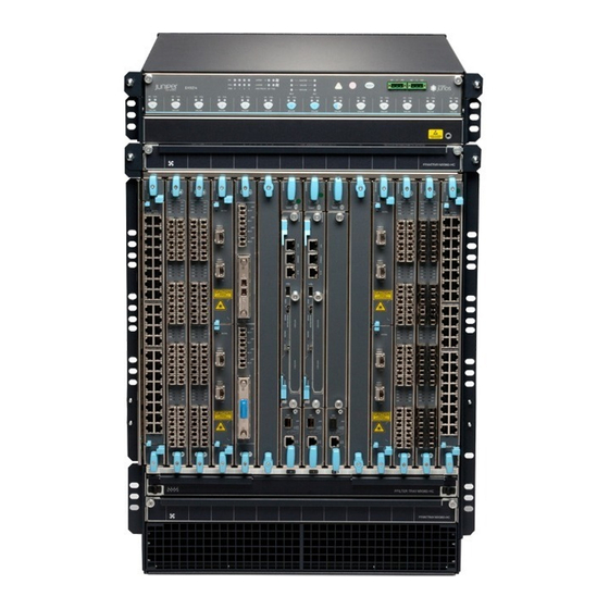
Page 28: Figure 1: Front View Of An Ex9214 Switch
EX9214 Switch Hardware Guide Figure 1: Front View of an EX9214 Switch ESD point Front-mounting Center-mounting Craft interface panel flange bracket Upper fan tray Line card slots SF2/LC6 Line card slots Air filter tray Lower fan tray Air intake Copyright © 2017, Juniper Networks, Inc. -
Page 29: Host Subsystem
Host Subsystem Switching and routing functionality, system management, and system control functions of an EX9214 switch are performed by the host subsystem. The host subsystem consists of a Routing Engine functioning together with a Switch Fabric. Copyright © 2017, Juniper Networks, Inc. -
Page 30: Line Cards
“EX9214 Switch Configurations” on page Line Cards The EX9214 switch has 12 vertical line card slots. The line cards for EX9214 switches combine a Packet Forwarding Engine and Ethernet interfaces in a single assembly. Line cards are field-replaceable units (FRUs) that you can install in the line card slots 1 through... -
Page 31: Cooling System
10-gigabit small form-factor pluggable plus (SFP+) transceivers Cooling System The cooling system in an EX9214 switch is a field-replaceable unit (FRU). It consists of two fully redundant hot-removable and hot-insertable fan trays and an air filter and provides front-to-back chassis cooling. See “Cooling System and Airflow in an EX9214... -
Page 32: Ex9214 Switch Configurations
EX9214 Switch Hardware Guide EX9214 Switch Configurations Table 5 on page 8 lists the three hardware configurations for an EX9214 switch—base (AC) and redundant (AC and DC versions)—and the components included in each configuration. Table 5: EX9214 Switch Hardware Configurations... - Page 33 Chapter 1: Switch Overview Table 5: EX9214 Switch Hardware Configurations (continued) First Junos OS Switch Configuration Configuration Components Release EX9214-REDUND3A-DC Chassis with craft interface and midplane 14.1 Three EX9200-SF2 modules Two EX9200-RE modules Two fan trays Four 4100 W DC power supplies...
-
Page 34: Ex9214 Switch Hardware And Cli Terminology Mapping
EX9214 Switch Hardware Overview on page 3 EX9214 Switch Hardware and CLI Terminology Mapping This topic describes the hardware terms used in EX9214 switch documentation and the corresponding terms used in the Junos OS CLI. See Table 6 on page... - Page 35 Chapter 1: Switch Overview Table 6: CLI Equivalents of Terms Used in Documentation for EX9214 Switches (continued) Hardware Item in Item (CLI) Description (CLI) Value (CLI) Documentation Additional Information Routing One of the following: n is a value in the range 0-1.
- Page 36 EX9214 Switch Hardware Guide Table 6: CLI Equivalents of Terms Used in Documentation for EX9214 Switches (continued) Hardware Item in Item (CLI) Description (CLI) Value (CLI) Documentation Additional Information MIC (n) Abbreviated name of n is a value in the range 0-1.
- Page 37 Chapter 1: Switch Overview Table 6: CLI Equivalents of Terms Used in Documentation for EX9214 Switches (continued) Hardware Item in Item (CLI) Description (CLI) Value (CLI) Documentation Additional Information Fan Tray (n) Fan Tray n is a value in the range 0-1.
- Page 38 EX9214 Switch Hardware Guide Copyright © 2017, Juniper Networks, Inc.
-
Page 39: Chassis Components And Descriptions
Switch Fabric Module LEDs in an EX9200 Switch on page 40 Cable Management Bracket in an EX9214 Switch on page 41 Chassis Physical Specifications of an EX9214 Switch The EX9214 switch chassis is a rigid sheet-metal structure that houses the other switch components. Table 7 on page 15 summarizes the physical specifications of the EX9214 switch chassis. - Page 40 EX9214 Switch Hardware Guide Table 7: Physical Specifications of the EX9214 Switch Chassis (continued) Description Weight Height Width Depth Routing Engine 2.4 lb (1.09 kg) 1.25 in. (3.2 cm) 11 in. (27.9 cm) 7.75 in. (19.7 cm) module (RE module) Switch Fabric 9.6 lb (4.4 kg) (with...
-
Page 41: Figure 4: Ex9214 Switch
Chapter 2: Chassis Components and Descriptions Table 7: Physical Specifications of the EX9214 Switch Chassis (continued) Description Weight Height Width Depth EX9200-40F-M line 14.8 lb (6.7 kg) 1.25 in. (3.2 cm) 17 in. (43.2 cm) 22 in. (55.9 cm) card EX9200-40XS line 17 lb (7.7 kg) -
Page 42: Figure 5: Rear View Of An Ex9214 Switch With Ac Power Supplies
Grounding points ESD point You can mount an EX9214 switch on a standard 19-in. four-post rack or a standard 800-mm enclosed cabinet. You can mount up to three EX9214 switches in a standard 48 rack unit (U) rack. Copyright © 2017, Juniper Networks, Inc. -
Page 43: Field-Replaceable Units In An Ex9200 Switch
Cabinet Requirements on page 91 Mounting an EX9200 Switch on a Rack or Cabinet Using a Mechanical Lift on page 141 Installing and Removing EX9214 Switch Hardware Components on page 144 Field-Replaceable Units in an EX9200 Switch Field-replaceable units (FRUs) are switch components that you can replace at your site. - Page 44 NOTE: Line cards are not part of the base or redundant configuration. You must order them separately. NOTE: If you have a Juniper J-Care service contract, register any addition, change, or upgrade of hardware components at . Failure https://www.juniper.net/customers/support/tools/updateinstallbase/ to do so can result in significant delays if you need replacement parts. This note does not apply if you replace existing components with the same type of component.
-
Page 45: Understanding Ex9214 Switch Component And Functionality Redundancy
To operate, each host subsystem requires a Routing Engine module (RE module) installed directly into in a Switch Fabric module (SF module). You can install up to 12 line cards in an EX9214 switch. You can install either a line card or an SF module in the slot nine (labeled 2 | 6 ). -
Page 46: Craft Interface In An Ex9200 Switch
. See “DC Power Supply in an EX9214 Switch” on page Cooling system—The cooling system in an EX9214 switch consists of two fan trays and one air filter. Each fan tray contains six fans. Under normal operating conditions, the fans in the fan trays run at less than full speed. If one of the fans fails, the host subsystem increases the speed of the remaining fans to provide sufficient cooling for the switch indefinitely. -
Page 47: Figure 8: Craft Interface In An Ex9208 Switch
Switch Fabric LEDs and control buttons 4— Minor alarm LED 9— Line card LEDs and control buttons 5—Major alarm LED Figure 9: Craft Interface in an EX9214 Switch 1— Power supply LEDs 6— Alarm cutoff/lamp test button 2— Fan LEDs 7—... -
Page 48: Host Subsystem Leds
LEDs. Table 10: Fan LEDs on the Craft Interface Label Status Description Green Fan is functioning normally. Unlit Fan is not installed. FAIL Fan has failed. Unlit Fan is not installed or functioning normally. Copyright © 2017, Juniper Networks, Inc. -
Page 49: Power Supply (Pem) Leds
You can turn a line card online or offline by using its control button on the craft interface. Table 13 on page 26 describes the function of the line card LEDs. Copyright © 2017, Juniper Networks, Inc. -
Page 50: Alarm Leds And Alarm Cutoff Button
Minor alarm LED – Deactivates major and minor alarms. Causes all LEDs on the craft interface to light (for testing) when pressed and held. Alarm cutoff/lamp test button Copyright © 2017, Juniper Networks, Inc. -
Page 51: Alarm Relay Contacts
EX9204 Switch Hardware Overview Documentation EX9208 Switch Hardware Overview EX9214 Switch Hardware Overview on page 3 Chassis Component Alarm Conditions on EX9200 Switches on page 284 Midplane in an EX9200 Switch The midplane is located on the rear of the chassis and forms the rear of the card cage. -
Page 52: Figure 11: Midplane In An Ex9204 Switch
EX9214 Switch Hardware Guide Figure 11: Midplane in an EX9204 Switch Midplane Figure 12: Midplane in an EX9208 Switch Midplane Copyright © 2017, Juniper Networks, Inc. -
Page 53: Routing Engine Module In An Ex9200 Switch
In an EX9204, EX9208, or EX9214 switch, you can install one or two RE modules in the Switch Fabric modules (SF modules) that are installed in slots on the front panel of the switch. - Page 54 USB memory card that loads the Junos OS. NOTE: In EX9214 switches, you must install an RE module only in the SF modules installed in slots 7 and 8 labeled If you have installed only one RE module, you must power off the switch before removing the RE module.
-
Page 55: Figure 14: Ex9200-Re Module In An Ex9200 Switch
Status LEDs—Indicate the status of the EX9200-RE module. Each EX9200-RE module has four LEDs labeled MASTER STORAGE ONLINE , and OK/FAIL on the faceplate. Captive screws—Secure the EX9200-RE module in place. Figure 15 on page 32 shows the EX9200-RE2 module in an EX9200 switch. Copyright © 2017, Juniper Networks, Inc. -
Page 56: Figure 15: Ex9200-Re2 Module In An Ex9200 Switch
Also provide secondary storage for log files and memory dump files. button—Reboots the EX9200-RE2 module when pressed. RESET Captive screws—Secure the EX9200-RE2 module in place. For the specifications of the Routing Engine modules, see Table 15 on page Copyright © 2017, Juniper Networks, Inc. -
Page 57: Switch Fabric Module In An Ex9200 Switch
In EX9204 and EX9208 switches, you can add a second SF module to the configuration for host subsystem redundancy. In EX9214 switches, you can add a third SF module to the configuration for host subsystem redundancy. If two SF modules are installed, one SF module functions as the master and the other functions as the backup. -
Page 58: Figure 16: Sf Module Ex9200-Sf
However, you must replace that EX9200-SF module with another EX9200-SF2 module for normal switch operation. See “Upgrading an EX9200-SF to an EX9200-SF2” on page 205. Figure 17 on page 35 shows the high-speed SF module, EX9200-SF2. Copyright © 2017, Juniper Networks, Inc. -
Page 59: Figure 17: Sf Module Ex9200-Sf2
Ethernet switch—Provides 1-Gbps link speeds between the Routing Engine and the line cards External clock interface—Allows BITS or GPS clock source input to the centralized timing circuit, or allows centralized timing to be output to BITS or GPS Copyright © 2017, Juniper Networks, Inc. -
Page 60: Host Subsystem In An Ex9200 Switch
A redundant configuration EX9204 and EX9208 switch has a second host subsystem. You can install either two or three host subsystems in the front panel of an EX9214 switch. A base configuration EX9214 switch has two host subsystems. A redundant configuration EX9214 switch has a third host subsystem. -
Page 61: Network Port Leds On Line Cards In An Ex9200 Switch
The Status LED in 10/100/1000BASE-T RJ-45 Ethernet network port indicates the status of one of the three port parameters—administrative status, speed, and duplex mode status. Table 17 on page 38 describes the Status LED. Copyright © 2017, Juniper Networks, Inc. -
Page 62: Modular Interface Card Led In An Ex9200 Switch
EX9200-40F-M Line Card on page 72 EX9200-40T Line Card on page 69 Table 18 on page 39 describes the MIC LED on line cards for EX9200 switches, its colors and state, and the status it indicates. Copyright © 2017, Juniper Networks, Inc. -
Page 63: Routing Engine Module Leds In An Ex9200 Switch
EX9204 Switch Hardware Overview Documentation EX9208 Switch Hardware Overview EX9214 Switch Hardware Overview on page 3 Routing Engine Module LEDs in an EX9200 Switch Each Routing Engine module (RE module) has LEDs on the module faceplate. Table 19 on page 39... -
Page 64: Switch Fabric Module Leds In An Ex9200 Switch
Removing an RE Module from an EX9200 Switch on page 201 Switch Fabric Module LEDs in an EX9200 Switch The Switch Fabric module (SF module) has three LEDs on the module faceplate. Table 21 on page 41 describes the functions of these LEDs. Copyright © 2017, Juniper Networks, Inc. -
Page 65: Cable Management Bracket In An Ex9214 Switch
Documentation Removing an SF Module from an EX9200 Switch on page 212 Taking the Host Subsystem Offline in an EX9200 Switch on page 203 Cable Management Bracket in an EX9214 Switch The cable management bracket (see Figure 18 on page... - Page 66 You can pull the cable management bracket up and outward to lock it into the maintenance position, so you can access the lower fan tray and the air filter. Related Installing the Cable Management Bracket in an EX9214 Switch on page 247 Documentation Copyright © 2017, Juniper Networks, Inc.
-
Page 67: Cooling System And Airflow
Cooling System and Airflow in an EX9214 Switch on page 43 Cooling System and Airflow in an EX9214 Switch The cooling system in an EX9214 switch consists of two field-replacable unit fan trays and an air filter that provide front-to-rear chassis cooling. -
Page 68: Airflow Direction In The Ex9214 Switch Chassis
See Figure 21 on page Figure 21: Airflow Through the EX9214 Switch Chassis The host subsystem monitors the temperature of switch components. Under normal operating conditions, the fans in the fan tray run at less than full speed. If a fan fails or the ambient temperature rises above the threshold, the speed of the remaining fans is automatically adjusted to keep the temperature within the acceptable range. -
Page 69: Power Supplies
The AC power supplies in EX9214 switches are hot-insertable and hot-removable field-replaceable units (FRUs). You can install either two or four AC power supplies in an EX9214 switch. Power supplies are installed at the rear of the chassis in slots through (left to right). -
Page 70: Figure 22: Ac Power Supply In An Ex9214 Switch
AC input switch and LEDs that indicate the status of the power supply. See Figure 22 on page Figure 22: AC Power Supply in an EX9214 Switch EX9214 switches support 4100 W AC power supply. The AC power supply supports 200–240 VAC AC power configurations. Copyright © 2017, Juniper Networks, Inc. -
Page 71: Ac Power Supply Configurations
AC appliance inlet on the power supply faceplate also. AC Power Supply Configurations EX9214 switches support two or four AC power supplies, installed vertically at the rear of the chassis in slots through... -
Page 72: Table 22: Ac Power Supply Leds In Ex9214 Switches
EX9214 Switch Hardware Guide Table 22: AC Power Supply LEDs in EX9214 Switches LEDs Feed Mode Description AC-1 OK AC-2 OK DC OK PS FAIL One-Feed The power input to the AC appliance inlet Green Green located on the chassis above the power... -
Page 73: Dc Power Supply In An Ex9214 Switch
Power Requirements for EX9200 Switch Components on page 95 DC Power Supply in an EX9214 Switch An EX9214 switch is configurable with four DC power supplies. The power supplies connect to the midplane, which distributes the different output voltages produced by the power supplies to the switch components, depending on their voltage requirements. -
Page 74: Dc Power Supply Description
DC Power Supply Description The DC power supplies in EX9214 switches are hot-insertable and hot-removable field-replaceable units (FRUs). You can install four DC power supplies in an EX9214 switch. Power supplies are installed at the rear of the chassis in slots through (left to right). -
Page 75: Dc Power Supply Configurations
DC power supply rated for at least 125% of the continuous current that the system draws at –40 VDC. DC Power Supply Configurations EX9214 switches support four DC power supplies, installed vertically at the rear of the chassis in slots through... -
Page 76: Table 23: Dc Power Supply Leds In Ex9214 Switches
EX9214 Switch Hardware Guide Table 23: DC Power Supply LEDs in EX9214 Switches LEDs Feed Mode Description INP0 OK INP1 OK DC OK PS FAIL One-Feed The power input to the INP-0 DC power Green Green inlet located on the power supply is... - Page 77 Chapter 4: Power Supplies Related DC Power Supply in an EX9214 Switch on page 49 Documentation Power Requirements for EX9200 Switch Components on page 95 Copyright © 2017, Juniper Networks, Inc.
- Page 78 EX9214 Switch Hardware Guide Copyright © 2017, Juniper Networks, Inc.
-
Page 79: Line Cards
Junos OS release in which the line card was first supported and the Switch Fabric module (SF module) that must be installed in the switch to support each line card. Copyright © 2017, Juniper Networks, Inc. -
Page 80: Table 24: Line Card Models For Ex9200 Switches
MICs: EX9200-10XS-MIC EX9200-20F-MIC EX9200-40T-MIC “EX9200-MPC Line Card” on page 62 EX9200-12QS A line card with six 40-Gigabit 16.1R1 EX9200-SF2 Ethernet rate-selectable ports, each of which can house transceivers “EX9200-12QS Line Card” on page 66 Copyright © 2017, Juniper Networks, Inc. -
Page 81: Ex9200-2C-8Xs Line Card
EX9204 Switch Hardware Overview Documentation EX9208 Switch Hardware Overview EX9214 Switch Hardware Overview on page 3 EX9200-2C-8XS Line Card The line cards in EX9200 switches combine a Packet Forwarding Engine and Ethernet interfaces in a single assembly. Line cards are field-replaceable units (FRUs) that you... -
Page 82: Line Card Models
Two 100-Gigabit Ethernet ports, each of which can house CFP transceivers. These ports support 100GBASE-LR4 and 100GBASE-SR10 transceivers. Eight 10-Gigabit Ethernet ports, each of which can house SFP+ transceivers. These ports support 10GBASE-SR, 10GBASE-LR, 10GBASE-ER, and 10GBASE-ZR transceivers. Copyright © 2017, Juniper Networks, Inc. -
Page 83: Ex9200-4Qs Line Card
Junos OS Release Model Description Required EX9200-4QS A line card with four 40-Gigabit Ethernet ports, 12.3R2 or later each of which can house 40-gigabit quad small form-factor pluggable plus (QSFP+) transceivers Figure 25 on page Copyright © 2017, Juniper Networks, Inc. -
Page 84: Line Card Components
Line cards are hot-insertable and hot-removable: You can remove and replace them without powering off the switch or disrupting switch functions. Copyright © 2017, Juniper Networks, Inc. -
Page 85: Line Card Models
LEDs for the 40-Gigabit Ethernet ports 3— LEDs for the 10-Gigabit Ethernet ports 6— 40-Gigabit Ethernet ports You can use the command to see the version of Junos OS for EX Series show version switches loaded on the switch. Copyright © 2017, Juniper Networks, Inc. -
Page 86: Line Card Components
Line cards are hot-insertable and hot-removable: You can remove and replace them without powering off the switch or disrupting switch functions. Copyright © 2017, Juniper Networks, Inc. -
Page 87: Line Card Models
You can transmit up to 130 gigabits of traffic through the line card without packet drop. Figure 27 on page Figure 27: EX9200-MPC Line Card 1— Ejector lever 3— MIC slots covered by cover panels 2—Line card LED Copyright © 2017, Juniper Networks, Inc. -
Page 88: Line Card Components
MIC indicates the status of the MIC. See “Modular Interface Card LED in an EX9200 Switch” on page 38. The MIC is shipped with 20 dust covers for the 20 ports. See Figure 29 on page Copyright © 2017, Juniper Networks, Inc. -
Page 89: Figure 29: Ex9200-20F-Mic
“Network Port LEDs on Line Cards in an EX9200 Switch” on page Related Line Card Model and Version Compatibility in an EX9200 Switch on page 55 Documentation Pluggable Transceivers Supported on EX9200 Switches on page 105 Copyright © 2017, Juniper Networks, Inc. -
Page 90: Ex9200-12Qs Line Card
“Switch Fabric Module in an EX9200 Switch” on page 33 “Installing an SF Module in an EX9200 Switch” on page 209. Figure 31 on page 67 shows the components of an EX9200-12QS line card. Copyright © 2017, Juniper Networks, Inc. -
Page 91: Line Card Components
Figure 31 on page 67). If a port is configured to operate at 10-Gbps speed, four 10-Gbps interfaces are created and the LEDs labeled , and for that port becomes operational. Each of these Copyright © 2017, Juniper Networks, Inc. -
Page 92: Ex9200-32Xs Line Card
Junos OS Release Model Description Required EX9200-32XS A line card with 32 10-Gigabit Ethernet ports, each 12.3R2 or later of which can house 10-gigabit small form-factor pluggable plus (SFP+) transceivers Figure 32 on page Copyright © 2017, Juniper Networks, Inc. -
Page 93: Line Card Components
(FRUs) that you can install in the line card slots on the front of the switch chassis. Line cards are hot-insertable and hot-removable: You can remove and replace them without powering off the switch or disrupting switch functions. Copyright © 2017, Juniper Networks, Inc. -
Page 94: Line Card Models
LED, the Status LED, which indicates the status of the port parameters. See “Network Port LEDs on Line Cards in an EX9200 Switch” on page Copyright © 2017, Juniper Networks, Inc. -
Page 95: Ex9200-40F Line Card
LEDs for the ports 2— Line card LED 5— 1-Gigabit Ethernet ports 3—MIC LED You can use the command to see the version of Junos OS for EX Series show version switches loaded on the switch. Copyright © 2017, Juniper Networks, Inc. -
Page 96: Line Card Components
Line Card Components on page 73 Line Card Models Table 33 on page 73 shows the model number, description of the line card model, and the Junos OS release in which the line card was first supported. Copyright © 2017, Juniper Networks, Inc. -
Page 97: Line Card Components
LEDs for the ports—One LED on each port, the Link/Activity LED, which indicates the link status and activity on the port. See “Network Port LEDs on Line Cards in an EX9200 Switch” on page Copyright © 2017, Juniper Networks, Inc. -
Page 98: Ex9200-40Xs Line Card
“Switch Fabric Module in an EX9200 Switch” on page 33 “Installing an SF Module in an EX9200 Switch” on page 209. Figure 36 on page 75 shows the components of an EX9200-40XS line card. Copyright © 2017, Juniper Networks, Inc. -
Page 99: Line Card Components
Handling and Storing Line Cards in EX9200 Switches on page 215 Line Card LED in an EX9200 Switch The line cards in EX9200 switches have an LED labeled on the faceplate that OK/FAIL indicates the online status information of line cards. Copyright © 2017, Juniper Networks, Inc. -
Page 100: Port Speeds
EX9204 Switch Hardware Overview Documentation EX9208 Switch Hardware Overview EX9214 Switch Hardware Overview on page 3 Configuring Rate Selectability on an EX9200-12QS Line Card to Enable Different Port Speeds Each of the six ports of PIC 0 and PIC 1 of an EX9200-12QS line card supports port speeds of 10 Gbps and 40 Gbps. - Page 101 10 Gbps or 40 Gbps; and ports 2 and 5 are enabled and the other ports of the PIC disabled if the speed specified is 100 Gbps. Table 36 on page 78 lists the physical ports that are enabled when the statement is configured. number-of-ports Copyright © 2017, Juniper Networks, Inc.
-
Page 102: Configuring Rate Selectability At The Port Level
3 speed 40g NOTE: All the six ports of PIC 0 and PIC 1 of an EX9200-12QS support 10-Gbps and 40-Gbps port speeds. However, only ports 2 and 5 of both the PICs support 100-Gbps speed. Copyright © 2017, Juniper Networks, Inc. -
Page 103: Line Cards
[edit chassis fpc 4 pic 0] user@host# show port 0 { speed 10g; port 1 { speed 10g; port 2 { speed 100g; port 3 { speed 40g; Commit your configuration changes. Reset the PIC. Copyright © 2017, Juniper Networks, Inc. - Page 104 If you configure rate selectability at the port level, logical interfaces are created only on the configured ports. No logical interfaces are created on the other ports. Related EX9200-12QS Line Card on page 66 Documentation Copyright © 2017, Juniper Networks, Inc.
-
Page 105: Site Planning, Preparation, And Specifications
PART 2 Site Planning, Preparation, and Specifications Preparation Overview on page 83 Planning Power Requirements on page 95 Transceiver and Cable Specifications on page 105 Pinout Specifications on page 125 Copyright © 2017, Juniper Networks, Inc. - Page 106 EX9214 Switch Hardware Guide Copyright © 2017, Juniper Networks, Inc.
-
Page 107: Preparation Overview
CHAPTER 6 Preparation Overview Site Preparation Checklist for an EX9214 Switch on page 83 Environmental Requirements and Specifications for EX Series Switches on page 85 General Site Guidelines on page 89 Site Electrical Wiring Guidelines on page 89 Rack Requirements on page 90... - Page 108 Acquire cables and connectors: Determine the number of cables needed based on your planned configuration. Ensure that the distance between hardware components to be connected allows for cable lengths to be within the specified maximum limits. Copyright © 2017, Juniper Networks, Inc.
-
Page 109: Environmental Requirements And Specifications For Ex Series Switches
Complies with Zone 4 degradation up to the relative humidity range temperature range 32° F (0° C) earthquake 5,000 feet 10% through 85% through 104° F (40° C) requirements as per (1524 meters) (noncondensing) GR-63, Issue 4. Copyright © 2017, Juniper Networks, Inc. - Page 110 (3048 meters) (noncondensing) range 32° F (0° C) through GR-63, Issue 4. 113° F (45° C) EX4550-32T switches—Normal operation is ensured in the temperature range 32° F through 104° F (40° C) Copyright © 2017, Juniper Networks, Inc.
- Page 111 10,000 feet 5% through 90% (0° C) through 104° F (40° C) requirements as per (3048 meters) (noncondensing) GR-63. Nonoperating storage temperature in shipping container: –40° F (–40° C) to 158° F (70° C) Copyright © 2017, Juniper Networks, Inc.
- Page 112 Clearance Requirements for Airflow and Hardware Maintenance for an EX8208 Switch Clearance Requirements for Airflow and Hardware Maintenance for an EX8216 Switch Clearance Requirements for Airflow and Hardware Maintenance for an EX9204 Switch Clearance Requirements for Airflow and Hardware Maintenance for an EX9208 Switch Copyright © 2017, Juniper Networks, Inc.
-
Page 113: General Site Guidelines
Chapter 6: Preparation Overview Clearance Requirements for Airflow and Hardware Maintenance for an EX9214 Switch on page 92 General Site Guidelines Efficient device operation requires proper site planning and maintenance and proper layout of the equipment, rack or cabinet (if used), and wiring closet. -
Page 114: Rack Requirements
Mounting bracket hole spacing The holes in the mounting brackets are spaced at 1 U (1.75 in. or 4.45 cm), so that the device can be mounted in any rack that provides holes spaced at that distance. Copyright © 2017, Juniper Networks, Inc. -
Page 115: Cabinet Requirements
The outer edges of the mounting brackets extend the width of the chassis to 19 in. (48.2 cm). The minimum total clearance inside the cabinet is 30 in. (76.2 cm) between the inside of the front door and the inside of the rear door. Copyright © 2017, Juniper Networks, Inc. -
Page 116: Switch
Documentation Clearance Requirements for Airflow and Hardware Maintenance for an EX9214 Switch When planning the site for installing an EX9214 switch, you must allow sufficient clearance around the switch. For the cooling system to function properly, the airflow around the chassis must be unrestricted. -
Page 117: Figure 38: Clearance Requirements For Airflow And Hardware Maintenance For An Ex9214 Switch With Ac Power Supplies
2.8 in. (7.1 cm) between the side of the chassis and any non-heat-producing surface such as a wall. See Figure 38 on page Figure 38: Clearance Requirements for Airflow and Hardware Maintenance for an EX9214 Switch with AC Power Supplies 31.08 (78.94 cm) 24" (61 cm) 26.85"... - Page 118 30 in. (72.6 cm) in front of the rack and 24 in. (61.0 cm) behind the rack. Related Rack-Mounting and Cabinet-Mounting Warnings on page 310 Documentation Rack Requirements on page 90 Cabinet Requirements on page 91 Cooling System and Airflow in an EX9214 Switch on page 43 Copyright © 2017, Juniper Networks, Inc.
-
Page 119: Planning Power Requirements
Power Requirements for EX9200 Switch Components on page 95 AC Power Supply Specifications for EX9214 Switches on page 96 AC Power Cord Specifications for an EX9214 Switch on page 97 DC Power Supply Specifications for EX9214 Switches on page 99... -
Page 120: Ac Power Supply Specifications For Ex9214 Switches
AC Power Supply Specifications for EX9214 Switches Table 43 on page 96 lists the power supply specifications for an AC power supply used in EX9214 switches. Table 43: AC Power Supply Specifications for an EX9214 Switch Item Specifications AC input voltage Operating range: 200–240 VAC... -
Page 121: Ac Power Cord Specifications For An Ex9214 Switch
AC Power Supply in an EX9214 Switch on page 45 Documentation AC Power Supply LEDs in an EX9214 Switch on page 47 AC Power Cord Specifications for an EX9214 Switch on page 97 AC Power Cord Specifications for an EX9214 Switch Each AC power supply has a single AC appliance inlet located on the power supply that requires a dedicated AC power feed. -
Page 122: Figure 40: Ac Plug Types
EX9214 Switch Hardware Guide Table 45: AC Power Cord Specifications for an EX9214 Switch (continued) Country Electrical Specification Plug Type Japan 220 VAC, 50 or 60 Hz AC NEMA L6-20P North America 250 VAC, 60 Hz AC NEMA L6-20P United Kingdom... -
Page 123: Dc Power Supply Specifications For Ex9214 Switches
AC power cord cables through the power cord tray provided with the switch. Related AC Power Supply in an EX9214 Switch on page 45 Documentation AC Power Electrical Safety Guidelines on page 330 AC Power Disconnection Warning on page 331... -
Page 124: Grounding Cable And Lug Specifications For Ex9200 Switches
DC Power Supply in an EX9214 Switch on page 49 Documentation DC Power Supply LEDs in an EX9214 Switch on page 51 Grounding Cable and Lug Specifications for EX9200 Switches To ensure proper operation and to meet safety and electromagnetic interference (EMI) requirements, you must connect an EX9200 switch to earth ground before you connect power to the switch. -
Page 125: Grounding Points Specifications For An Ex9200 Switch
The same cable lug is used for the DC power cables. Grounding Cable Specifications for an EX9200 Switch The grounding cable that you provide must meet the specifications in Table 48 on page 102. Copyright © 2017, Juniper Networks, Inc. -
Page 126: Calculating The Ex Series Switch Fiber-Optic Cable Power Budget
), minimum 60°C wire, or one that complies with the by the local code For DC-powered EX9214 switches, the 48 VDC facility must be equipped with a circuit breaker rated 40 A (–48 VDC), or 60 A (–48 VDC), and the grounding cable must be minimum 10 AWG, or one that complies with the by the local code. -
Page 127: Calculating The Ex Series Switch Fiber-Optic Cable Power Margin
Multimode—None, if product of 0 dBm bandwidth and distance is less than 0 dBm 500 MHz/km Single mode—None Connector 0.5 dBm This example assumes 5 connectors. Loss for 5 connectors: (5) * (0.5 dBm) = 2.5 dBm Copyright © 2017, Juniper Networks, Inc. - Page 128 Calculating the EX Series Switch Fiber-Optic Cable Power Budget on page 102 Documentation Understanding EX Series Switches Fiber-Optic Cable Signal Loss, Attenuation, and Dispersion on page 123 Pluggable Transceivers Supported on EX Series Switches on page 106 Copyright © 2017, Juniper Networks, Inc.
-
Page 129: Transceiver And Cable Specifications
You can find the list of transceivers supported on EX9208 switches and information about those transceivers at the Hardware Compatibility Tool page for EX9208 You can find the list of transceivers supported on EX9214 switches and information about those transceivers at the Hardware Compatibility Tool page for EX9214... -
Page 130: Pluggable Transceivers Supported On Ex Series Switches
EX9214 Switch Hardware Guide replace it with an equivalent Juniper Networks optic or cable that is qualified for the device. The Gigabit Ethernet SFP, SFP+, and QSFP+ transceivers and the 100GBASE-LR4 CFP transceivers installed in EX9200 switches support digital optical monitoring (DOM): You... - Page 131 (JTAC) can help you diagnose the source of the problem. Your JTAC engineer might recommend that you check the third-party optic or cable and potentially replace it with an equivalent Juniper Networks optic or cable that is qualified for the device.
- Page 132 EX4300—Optional uplink modules for EX4300 switches support SFP, SFP+, and QSFP+ transceivers. You can find the list of transceivers supported on EX4300 switches and information about those transceivers at the Hardware Compatibility Tool page for EX4300 Copyright © 2017, Juniper Networks, Inc.
- Page 133 EX4600 switches and information about those transceivers at the Hardware Compatibility Tool page for EX4600 EX6200—Uplink ports on the Switch Fabric and Routing Engine (SRE) module and line cards in EX6200 switches support SFP and SFP+ transceivers. You can find the Copyright © 2017, Juniper Networks, Inc.
-
Page 134: Sfp+ Direct Attach Copper Cables For Ex Series Switches
You can find the list of transceivers supported on EX9208 switches and information about those transceivers at the Hardware Compatibility Tool page for EX9208 You can find the list of transceivers supported on EX9214 switches and information about those transceivers at the Hardware Compatibility Tool page for EX9214... -
Page 135: Cable Specifications
EX4200-24PX, EX4200-24F, EX4200-24F-DC, EX4200-48T, EX4200-48T-DC, EX4200-48P, and EX4200-48PX switches EX4200-24F-S and Junos OS Release 12.3R4 3 ft (1 m), 10 ft (3 m), 16 ft (5 m), and 23 ft (7 m) EX4200-48T-S switches Copyright © 2017, Juniper Networks, Inc. - Page 136 3 ft (1 m), 10 ft (3 m), and 23 ft (7 m) line cards (EX8200-40XS) Junos OS Release 11.1 16 ft (5 m) NOTE: We recommend that you use only SFP+ DAC cables purchased from Juniper Networks with your Juniper Networks device. Copyright © 2017, Juniper Networks, Inc.
-
Page 137: Table 51: Sfp+ Direct Attach Copper Cable Specifications
(JTAC) can help you diagnose the source of the problem. Your JTAC engineer might recommend that you check the third-party optic or cable and potentially replace it with an equivalent Juniper Networks optic or cable that is qualified for the device. - Page 138 30 AWG Minimum cable bend radius 1 in. (2.54 cm) Cable characteristic impedance 100 ohms Crosstalk between pairs 2% maximum Time delay 1.31 nsec/ft Length 9.9 ft (3 m) Support for Virtual Chassis configuration Copyright © 2017, Juniper Networks, Inc.
- Page 139 24 AWG Minimum cable bend radius 1 in. (2.54 cm) Cable characteristic impedance 100 ohms Crosstalk between pairs 2% maximum Time delay 1.31 nsec/ft Length 16.4 ft (5 m) Support for Virtual Chassis configuration Copyright © 2017, Juniper Networks, Inc.
-
Page 140: Standards Supported By These Cables
Electrical interface standard SFF-8432—see ftp://ftp.seagate.com/sff/SFF-8432.PDF SFP+ Multi-Source Alliance (MSA) standards Related Pluggable Transceivers Supported on EX Series Switches on page 106 Documentation Installing a Transceiver on page 235 Removing a Transceiver on page 237 Copyright © 2017, Juniper Networks, Inc. -
Page 141: Qsfp+ Direct Attach Copper Cables For Ex Series Switches
EX Series switches for Junos OS releases. Table 52: Software Support for QSFP+ Passive Direct Attach Copper Cables for EX Series Switches Switch Software Support Added DAC Model Number EX3400 switches Junos OS Release 15.1X53-D50 EX-QSFP-40GE-DAC-50CM QFX-QSFP-DAC-1M QFX-QSFP-DAC-3M JNP-QSFP-DAC-5M Copyright © 2017, Juniper Networks, Inc. - Page 142 (JTAC) can help you diagnose the source of the problem. Your JTAC engineer might recommend that you check the third-party optic or cable and potentially replace it with an equivalent Juniper Networks optic or cable that is qualified for the device.
-
Page 143: Table 53: Qsfp+ Direct Attach Copper Cable Specifications
30 AWG Minimum cable bend radius 2.54 cm (1 in.) Cable characteristic impedance 100 ohms Crosstalk between pairs 1% maximum Time delay 4.3 nsec/ft Length 1.6 ft (0.5 m) Support for Virtual Chassis configuration Copyright © 2017, Juniper Networks, Inc. - Page 144 30 AWG Minimum cable bend radius 2.54 cm (1 in.) Cable characteristic impedance 100 ohms Crosstalk between pairs 1% maximum Time delay 4.3 nsec/ft Length 3.28 ft (1 m) Support for Virtual Chassis configuration Copyright © 2017, Juniper Networks, Inc.
- Page 145 30 AWG Minimum cable bend radius 2.54 cm (1 in.) Cable characteristic impedance 100 ohms Crosstalk between pairs 1% maximum Time delay 4.3 nsec/ft Length 9.84 ft (3 m) Support for Virtual Chassis configuration Copyright © 2017, Juniper Networks, Inc.
-
Page 146: Management Cable Specifications
CAT5e UTP (unshielded RJ-45 Connecting a Device to a twisted pair) cable Management Console by Using an RJ-45 Connector Management ( – – Connecting a Device to a MGMT Ethernet port (10/100/1000) Network for Out-of-Band Management Copyright © 2017, Juniper Networks, Inc. -
Page 147: Understanding Ex Series Switches Fiber-Optic Cable Signal Loss, Attenuation
Although attenuation is significantly lower for optical fiber than for other media, it still occurs in both multimode and single-mode transmission. An efficient optical data link must transmit enough light to overcome attenuation. Copyright © 2017, Juniper Networks, Inc. - Page 148 (including those from dispersion), and a safety margin for unexpected losses. Related Calculating the EX Series Switch Fiber-Optic Cable Power Budget on page 102 Documentation Calculating the EX Series Switch Fiber-Optic Cable Power Margin on page 103 Copyright © 2017, Juniper Networks, Inc.
-
Page 149: Pinout Specifications
RJ-45 to DB-9 Serial Port Adapter Pinout Information on page 127 Console Port Connector Pinout Information The console port on a Juniper Networks device is an RS-232 serial interface that uses an RJ-45 connector to connect to a console management device. The default baud rate for the console port is 9600 baud. -
Page 150: Usb Port Specifications For An Ex Series Switch
Documentation Configuring the Console Port Type (CLI Procedure) USB Port Specifications for an EX Series Switch The following Juniper Networks USB flash drives have been tested and are officially supported for the USB port on all EX Series switches: RE-USB-1G-S... -
Page 151: Rj-45 Management Port Connector Pinout Information
Booting an EX Series Switch Using a Software Package Stored on a USB Flash Drive RJ-45 Management Port Connector Pinout Information Table 56 on page 127 provides the pinout information for the RJ-45 connector for the management port on Juniper Networks devices. Table 56: RJ-45 Management Port Connector Pinout Information Signal Description... -
Page 152: Table 57: Rj-45 To Db-9 Serial Port Adapter Pinout Information
RJ-45 to DB-9 serial port adapter. Table 57: RJ-45 to DB-9 Serial Port Adapter Pinout Information RJ-45 Pin Signal DB-9 Pin Signal Related Connecting a Device to a Management Console by Using an RJ-45 Connector Documentation Copyright © 2017, Juniper Networks, Inc. -
Page 153: Initial Installation And Configuration
Unpacking the Switch on page 131 Installing the Switch on page 137 Connecting the Switch to Power on page 147 Connecting the Switch to the Network on page 165 Performing Initial Configuration on page 171 Copyright © 2017, Juniper Networks, Inc. - Page 154 EX9214 Switch Hardware Guide Copyright © 2017, Juniper Networks, Inc.
-
Page 155: Unpacking The Switch
Unpacking the EX9200 Switch on page 131 Unpacking a Line Card Used in an EX9200 Switch on page 132 Parts Inventory (Packing List) for an EX9214 Switch on page 134 Registering Products—Mandatory for Validating SLAs on page 136 Unpacking the EX9200 Switch The switch is shipped in a wooden crate. -
Page 156: Unpacking A Line Card Used In An Ex9200 Switch
Unpacking a Line Card Used in an EX9200 Switch The line cards for EX9200 switches are rigid sheet-metal structures that house the line card components including network ports. The line cards are shipped in a cardboard carton, secured with foam packing material. Copyright © 2017, Juniper Networks, Inc. -
Page 157: Figure 45: Unpacking A Line Card Used In An Ex9200 Switch
Figure 45: Unpacking a Line Card Used in an EX9200 Switch Related Installing a Line Card in an EX9200 Switch on page 220 Documentation EX9204 Switch Hardware Overview EX9208 Switch Hardware Overview EX9214 Switch Hardware Overview on page 3 Copyright © 2017, Juniper Networks, Inc. -
Page 158: Parts Inventory (Packing List) For An Ex9214 Switch
EX9214 Switch Hardware Guide Parts Inventory (Packing List) for an EX9214 Switch The EX9214 switches are shipped in a cardboard carton, secured with foam packing material. The carton also contains an accessory box. The switch shipment includes a packing list. Check the parts you receive in the switch shipping crate against the items on the packing list. -
Page 159: Table 59: Accessory Box Parts List
Chapter 10: Unpacking the Switch Table 58: Parts List for Different EX9214 Switch Configurations (continued) Redundant Configuration Component Base Configuration Quantity Quantity Cover panels for slots without Cover panels for empty line Cover panels for empty line installed components card slots: 12... -
Page 160: Registering Products-Mandatory For Validating Slas
Documentation EX9214 Switch Hardware Overview on page 3 Registering Products—Mandatory for Validating SLAs Register all new Juniper Networks hardware products and changes to an existing installed product using the Juniper Networks website to activate your hardware replacement service-level agreements (SLAs). -
Page 161: Installing The Switch
Installing the Switch Installing and Connecting an EX9214 Switch on page 137 Installing a Mounting Shelf in a Rack or Cabinet for an EX9214 Switch on page 138 Moving the Mounting Brackets for Center-Mounting an EX9200 Switch on page 140... -
Page 162: Installing A Mounting Shelf In A Rack Or Cabinet For An Ex9214 Switch
Installing a Mounting Shelf in a Rack or Cabinet for an EX9214 Switch The EX9214 switch can be installed in a four-post rack or cabinet or in an open-frame rack. You must install the mounting shelf, which is included in the shipping container, on the rack before installing the switch because the weight of a fully loaded chassis can be up to 350 lb (158.8 kg). - Page 163 Hang the shelf over the mounting screws by using the keyhole slots located near the top of the shelf flanges. Partially insert screws into the open holes in the flanges of the mounting shelf. See Figure 46 on page 140. Copyright © 2017, Juniper Networks, Inc.
-
Page 164: Moving The Mounting Brackets For Center-Mounting An Ex9200 Switch
Two removable mounting brackets are attached to the mounting holes closest to the front of the chassis. You can move the pair of brackets to another position on the side of the chassis for center-mounting the switch. Copyright © 2017, Juniper Networks, Inc. -
Page 165: Mounting An Ex9200 Switch On A Rack Or Cabinet Using A Mechanical Lift
Installing a Mounting Shelf in a Rack or Cabinet for an EX9208 Switch Installing a Mounting Shelf in a Rack or Cabinet for an EX9214 Switch on page 138 Mounting an EX9200 Switch on a Rack or Cabinet Using a Mechanical Lift Because of the size and weight of the switch, we strongly recommend using a mechanical lift to install the switch. - Page 166 Mounting Shelf in a Rack or Cabinet for an EX9204 Switch, Installing a Mounting Shelf in a Rack or Cabinet for an EX9208 Switch, or “Installing a Mounting Shelf in a Rack or Cabinet for an EX9214 Switch” on page 138. Review chassis lifting guidelines described in Chassis Lifting Guidelines for EX9200 Switches.
- Page 167 Figure 47 on page 144 shows installing an EX9208 switch in an open-frame rack. The procedure is the same for all EX9200 switches. Copyright © 2017, Juniper Networks, Inc.
-
Page 168: Installing And Removing Ex9214 Switch Hardware Components
Powering On a DC-Powered EX9200 Switch on page 162 Connecting and Configuring an EX9200 Switch (CLI Procedure) on page 172 Installing and Removing EX9214 Switch Hardware Components The field-replaceable units (FRUs) in an EX9214 switch are: Routing Engine module (RE module) Switch Fabric module (SF module) - Page 169 “Removing a Line Card from an EX9200 Switch” on page 222. To install an AC power supply in an EX9214 switch, follow instructions in “Installing an AC Power Supply in an EX9214 Switch” on page 189. To remove a power supply from an EX9214 switch, follow instructions in “Removing an AC Power Supply from an EX9214...
- Page 170 EX9214 Switch Hardware Guide Copyright © 2017, Juniper Networks, Inc.
-
Page 171: Connecting The Switch To Power
Connecting the Switch to Power Connecting Earth Ground to an EX Series Switch on page 147 Connecting AC Power to an EX9214 Switch on page 154 Powering On an AC-Powered EX9200 Switch on page 156 Connecting DC Power to an EX9214 Switch on page 158... -
Page 172: Parts And Tools Required For Connecting An Ex Series Switch To Earth Ground
Phillips (+) of the minimum 90°C LCC10-14BWL or screws with #10 number 2 chassis wire, or as equivalent— split-lock washer— permitted by the not provided not provided local code Two #10 flat washers— not provided Copyright © 2017, Juniper Networks, Inc. - Page 173 LCD2-14A-Q or screws with #¼” number 2 chassis (on same gage as the equivalent split-washer lower left power feed cables —provided —provided side) and as permitted Two #¼” flat by the local code. washers— provided Copyright © 2017, Juniper Networks, Inc.
- Page 174 #¼” number 2 “Grounding chassis 60°C wire, or one equivalent— split-washer— Cable and that complies with provided provided the local code Specifications Two #¼” flat for EX9200 washers— Switches” on provided page 100. Copyright © 2017, Juniper Networks, Inc.
-
Page 175: Special Instructions To Follow Before Connecting Earth Ground To A
Switch Special Instructions EX3200 NOTE: Some early variants of EX3200 switches for which the Juniper Networks model number on the label next to the protective earthing terminal is from 750-021xxx through 750-030xxx require 10-24x.25 in. screws. EX4200 NOTE: Some early variants of EX4200 switches for which the Juniper Networks model number on the label next to the protective earthing terminal is from 750-021xxx through 750-030xxx require 10-24x.25 in. -
Page 176: Connecting Earth Ground To An Ex Series Switch
Figure 49: Connecting a Grounding Cable to an EX Series Switch Secure the grounding lug to the protective earthing terminal with the washers and screws. Dress the grounding cable and ensure that it does not touch or block access to other switch components. Copyright © 2017, Juniper Networks, Inc. - Page 177 Connecting AC Power to an EX9208 Switch Connecting DC Power to an EX9208 Switch Connecting AC Power to an EX9214 Switch on page 154 Connecting DC Power to an EX9214 Switch on page 158 General Safety Guidelines and Warnings on page 299 Grounded Equipment Warning on page 314 Copyright ©...
-
Page 178: Connecting Ac Power To An Ex9214 Switch
EX9214 Switch Hardware Guide Connecting AC Power to an EX9214 Switch You can install up to four AC power supplies in EX9214 switches. CAUTION: Do not mix different types of power supplies (AC and DC) in the same chassis. NOTE: Each power supply must be connected to a dedicated AC power source outlet and a dedicated customer site circuit breaker. - Page 179 Ensure that the power supply is fully inserted and latched securely in the chassis. See “Installing an AC Power Supply in an EX9214 Switch” on page 189. Rotate the metal cover next to the appliance inlet on the power supply faceplate away to expose the input mode switch.
-
Page 180: Powering On An Ac-Powered Ex9200 Switch
Powering On an AC-Powered EX9200 Switch on page 156 Documentation AC Power Supply in an EX9214 Switch on page 45 AC Power Supply LEDs in an EX9214 Switch on page 47 Powering On an AC-Powered EX9200 Switch Before you power on the switch, ensure that: You have installed all required switch components. - Page 181 Switch, Connecting AC Power to an EX9208 Switch, or “Connecting AC Power to an EX9214 Switch” on page 154. On the external management device, monitor the startup process to ensure that the system boots properly. Copyright © 2017, Juniper Networks, Inc.
-
Page 182: Connecting Dc Power To An Ex9214 Switch
Installing an AC Power Supply in an EX9204 Switch Documentation Installing an AC Power Supply in an EX9208 Switch Installing an AC Power Supply in an EX9214 Switch on page 189 Connecting DC Power to an EX9214 Switch You can install four DC power supplies in EX9214 switches. - Page 183 ESD grounding strap DC power source cables (not provided) with the cable lugs (provided) attached. The provided cable lugs in an EX9214 switch are sized for 6 AWG (13.3 mm ) power source cables. The DC power source cables that you provide must be 6 AWG (13.3 mm minimum 60°C wire.
- Page 184 Ensure that each nut is properly threaded onto the terminal stud. You must be able to spin the nuts freely with your fingers when they are placed onto the terminal stud Copyright © 2017, Juniper Networks, Inc.
- Page 185 B. This configuration provides the commonly deployed A/B feed redundancy for the system. For information about connecting to DC power sources, see “DC Power Supply Specifications for EX9214 Switches” on page Verify that the LED on the power supply are lit green steadily. If...
-
Page 186: Powering On A Dc-Powered Ex9200 Switch
Powering On a DC-Powered EX9200 Switch on page 162 Documentation DC Power Supply in an EX9214 Switch on page 49 DC Power Supply LEDs in an EX9214 Switch on page 51 Powering On a DC-Powered EX9200 Switch Before you power on the switch, ensure that: You have installed all required switch components. - Page 187 ) position if you move the breaker too quickly. If any of the status LEDs indicates that the power supply is not functioning normally, repeat the installation and cabling procedures. See Connecting DC Power to an EX9204 Copyright © 2017, Juniper Networks, Inc.
- Page 188 Related Installing a DC Power Supply in an EX9204 Switch Documentation Installing a DC Power Supply in an EX9208 Switch Installing a DC Power Supply in an EX9214 Switch on page 193 Copyright © 2017, Juniper Networks, Inc.
-
Page 189: Connecting The Switch To The Network
Routing Engine module (RE module) installed in the switch. For the location of the Ethernet management port, see Figure 53 on page 166. Connect the other end of the Ethernet cable to the management device. Copyright © 2017, Juniper Networks, Inc. -
Page 190: Figure 53: Ethernet Management Port On The Re Module In Ex9200 Switches
RJ-45 to DB-9 female adapter supplied with the device and a USB to DB-9 male adapter. You must provide the USB to DB-9 male adapter. To connect the device to a management console or auxiliary device: Turn off the power to the console or auxiliary device. Copyright © 2017, Juniper Networks, Inc. -
Page 191: Connecting The Ex9200 Switch To An External Alarm-Reporting Device
With the small screws on its side facing left, insert wires into the slots in the front of the block based on the wiring for the external device. Tighten the screws to secure the wire. Copyright © 2017, Juniper Networks, Inc. -
Page 192: Switch
Insert the replacement wires into the slots in the front of the block. Use the screwdriver to tighten the screws and secure the wire. Attach an ESD grounding strap to your bare wrist, and connect the strap to one of the ESD points on the chassis. Copyright © 2017, Juniper Networks, Inc. -
Page 193: Connecting A Fiber-Optic Cable
If the fiber-optic cable connector is covered with a rubber safety cap, remove the cap. Save the cap. Remove the rubber safety cap from the optical transceiver. Save the cap. Insert the cable connector into the optical transceiver (see Figure 58 on page 170). Copyright © 2017, Juniper Networks, Inc. -
Page 194: Figure 58: Connecting A Fiber-Optic Cable To An Optical Transceiver Installed
Related Disconnecting a Fiber-Optic Cable from a Device on page 244 Documentation Installing a Transceiver on page 235 Maintaining Fiber-Optic Cables on page 245 Copyright © 2017, Juniper Networks, Inc. -
Page 195: Performing Initial Configuration
This topic shows the factory default configuration file of an EX9200 switch: system { arp { aging-timer 5; syslog { user * { any emergency; file messages { any notice; authorization info; file interactive-commands { interactive-commands any; protocols { lldp { interface all; Copyright © 2017, Juniper Networks, Inc. -
Page 196: Connecting And Configuring An Ex9200 Switch (Cli Procedure)
Understanding Configuration Files for EX Series Switches EX9204 Switch Hardware Overview EX9208 Switch Hardware Overview EX9214 Switch Hardware Overview on page 3 Connecting and Configuring an EX9200 Switch (CLI Procedure) The EX9200 switch is shipped with the Junos OS preinstalled and ready to be configured when the switch is powered on. - Page 197 Configure the name of the switch. If the name includes spaces, enclose the name in quotation marks (“ ”). [edit] root@# set system host-name host-name Create a user account. [edit] root@# set system login user user-name authentication plain-text-password New password: password Retype new password: password Copyright © 2017, Juniper Networks, Inc.
- Page 198 (Optional) Display the configuration to verify that it is correct. [edit] root@# show system { host-name host-name; domain-name domain-name; root-authentication { authentication-method (password | public-key); name-server { address; interfaces { fxp0 { unit 0 { family inet { address address/prefix-length; Copyright © 2017, Juniper Networks, Inc.
- Page 199 If the switch boots from an alternate boot device, Junos OS displays a message indication this when you log in to the switch. Related EX9204 Switch Hardware Overview Documentation EX9208 Switch Hardware Overview EX9214 Switch Hardware Overview on page 3 Copyright © 2017, Juniper Networks, Inc.
- Page 200 EX9214 Switch Hardware Guide Copyright © 2017, Juniper Networks, Inc.
-
Page 201: Installing, Maintaining, And Replacing Components
Replacing Alarm Relay Wire on page 241 Maintaining and Replacing Fiber-Optic Cable on page 243 Replacing Cable Management Bracket on page 247 Routine Maintenance on page 251 Contacting Customer Support and Returning the Chassis or Components on page 263 Copyright © 2017, Juniper Networks, Inc. - Page 202 EX9214 Switch Hardware Guide Copyright © 2017, Juniper Networks, Inc.
-
Page 203: Removing The Switch
Routing Engine, issue the command.) request system halt For more information about these commands, see the Junos OS Operational Mode Commands. Wait until a message appears on the console confirming that the operating system has halted. Copyright © 2017, Juniper Networks, Inc. -
Page 204: Removing An Ex9200 Switch From A Rack Or Cabinet Using A Mechanical Lift
Connecting AC Power to an EX9208 Switch Connecting DC Power to an EX9208 Switch Connecting AC Power to an EX9214 Switch on page 154 Connecting DC Power to an EX9214 Switch on page 158 Removing an EX9200 Switch from a Rack or Cabinet Using a Mechanical Lift Considering the size and weight of the switch, we strongly recommend you use a mechanical lift to remove the switch. - Page 205 Carefully slide the switch from the adjustable mounting brackets attached to the rack onto the lift. Use the lift to transport the switch to its new location. Related Mounting an EX9200 Switch on a Rack or Cabinet Using a Mechanical Lift on page 141 Documentation Copyright © 2017, Juniper Networks, Inc.
- Page 206 EX9214 Switch Hardware Guide Copyright © 2017, Juniper Networks, Inc.
-
Page 207: Replacing Cooling System Component
Grasp the fan tray handle, and insert it straight into the chassis. Note the correct orientation by the label on the top surface of the fan tray. This side up Tighten the captive screws using a screwdriver on the fan tray faceplate to secure it in the chassis. Copyright © 2017, Juniper Networks, Inc. -
Page 208: Figure 59: Installing A Fan Tray In An Ex9208 Switch
EX9208 switch. The procedure and orientation of the fan tray are the same for EX9204. The procedure is the same for EX9214 switch; however, the orientation of the fan try is different—it is installed horizontally into... -
Page 209: Figure 60: Installing The Upper Fan Tray In An Ex9214 Switch
Chapter 16: Replacing Cooling System Component Figure 60: Installing the Upper Fan Tray in an EX9214 Switch NOTE: If you have a Juniper J-Care service contract, register any addition, change, or upgrade of hardware components at https://www.juniper.net/customers/support/tools/updateinstallbase/ . Failure to do so can result in significant delays if you need replacement parts. This note does not apply if you replace existing components with the same type of component. -
Page 210: Removing A Fan Tray From An Ex9200 Switch
EX9204. The procedure is the same for EX9214 switch; however, the orientation of the fan try is different— it is installed horizontally into the top and bottom of the chassis (see Figure 62 on page 188). -
Page 211: Figure 61: Removing A Fan Tray From An Ex9200 Switch
Chapter 16: Replacing Cooling System Component Figure 61: Removing a Fan Tray from an EX9200 Switch Copyright © 2017, Juniper Networks, Inc. -
Page 212: Figure 62: Removing The Upper Fan Tray In An Ex9214 Switch
EX9214 Switch Hardware Guide Figure 62: Removing the Upper Fan Tray in an EX9214 Switch Related Installing a Fan Tray in an EX9200 Switch on page 183 Documentation Cooling System and Airflow in an EX9204 Switch Cooling System and Airflow in an EX9208 Switch... -
Page 213: Replacing Power Supply
Removing a DC Power Supply from an EX9214 Switch on page 196 Installing an AC Power Supply in an EX9214 Switch The AC power supply in an EX9214 switch is a hot-insertable and hot-removable field-replaceable unit (FRU) installed in the rear panel. Up to four AC power supplies can be installed in an EX9214 switch. -
Page 214: Figure 63: Installing An Ac Power Supply In An Ex9214 Switch
Figure 63 on page 190). Ensure that the power supply faceplate is flush with any adjacent power supply faceplates or power supply cover panels. Figure 63: Installing an AC Power Supply in an EX9214 Switch Copyright © 2017, Juniper Networks, Inc. -
Page 215: Removing An Ac Power Supply From An Ex9214 Switch
Field-Replaceable Units in an EX9200 Switch on page 19 Removing an AC Power Supply from an EX9214 Switch The AC power supply in an EX9214 switch is a hot-removable and hot-insertable field-replaceable unit (FRU) installed in the rear panel. CAUTION: Before you remove a power supply, ensure that you have power supplies sufficient to power the switch that remains in the chassis. - Page 216 Do not leave the power supply slot empty for a long time while the switch is operational. Either replace the power supply promptly or install a cover panel over the empty slot. To remove an AC power supply from an EX9214 switch (see Figure 64 on page 193): Switch off the dedicated customer site circuit breaker for the power supply and remove the power cord from the AC power source.
-
Page 217: Installing A Dc Power Supply In An Ex9214 Switch
AC Power Supply in an EX9214 Switch on page 45 Installing a DC Power Supply in an EX9214 Switch The DC power supply in an EX9214 switch is a hot-insertable and hot-removable field-replaceable unit (FRU) installed in the rear panel. Up to four DC power supplies can be installed in an EX9214 switch. - Page 218 Ensure that you have the following parts and tools available: ESD grounding strap Phillips (+) screwdriver, number 1 To install a DC power supply in an EX9214 switch: Attach the ESD grounding strap to your bare wrist, and connect the strap to the ESD point on the chassis.
-
Page 219: Figure 65: Installing A Dc Power Supply In An Ex9214 Switch
Chapter 17: Replacing Power Supply Figure 65: Installing a DC Power Supply in an EX9214 Switch While firmly pushing the handle of the power supply with one hand, use the other hand to pull the spring-loaded locking pin in the release lever away from the chassis and turn the release lever in the clockwise direction until it stops. -
Page 220: Removing A Dc Power Supply From An Ex9214 Switch
Field-Replaceable Units in an EX9200 Switch on page 19 Removing a DC Power Supply from an EX9214 Switch The DC power supply in an EX9214 switch is a hot-removable and hot-insertable field-replaceable unit (FRU). You remove DC power supplies from the front of the chassis. - Page 221 Chapter 17: Replacing Power Supply To remove a DC power supply from an EX9214 switch: Switch off the dedicated customer site circuit breaker for the power supply being removed. Follow your site's procedures for ESD. Make sure that the voltage across the DC power source cable leads is 0 V and that there is no chance that the cables might become active during the removal process.
-
Page 222: Figure 66: Removing A Dc Power Supply From An Ex9214 Switch
Do not touch the connector on the top of the power supply. Pull the power supply straight out of the chassis. Related Installing a DC Power Supply in an EX9214 Switch on page 193 Documentation DC Power Supply in an EX9214 Switch on page 49... -
Page 223: Replacing Routing Engine (Re) Module
Each RE module is installed horizontally in a Switch Fabric module (SF module) installed in the switch. NOTE: In an EX9214 switch, you must install an RE module only in the SF modules installed in slots 7 and 8 labeled CAUTION: Do not lift the RE module by holding the ejector handles. - Page 224 Routing show chassis routing-engine Engines. Figure 67 on page 201 shows installing an RE module in an EX9204 switch. The procedure is the same for all EX9200 switches. Copyright © 2017, Juniper Networks, Inc.
-
Page 225: Removing An Re Module From An Ex9200 Switch
Chapter 18: Replacing Routing Engine (RE) Module Figure 67: Installing an RE Module in an EX9200 Switch module NOTE: If you have a Juniper J-Care service contract, register any addition, change, or upgrade of hardware components at https://www.juniper.net/customers/support/tools/updateinstallbase/ . Failure to do so can result in significant delays if you need replacement parts. - Page 226 Place the RE module in the antistatic bag or on the antistatic mat. CAUTION: Do not stack hardware components on one another after you remove them. Place each component on an antistatic mat resting on a stable, flat surface. Copyright © 2017, Juniper Networks, Inc.
-
Page 227: Taking The Host Subsystem Offline In An Ex9200 Switch
If the host subsystem is functioning as the master, switch it to backup using the request chassis routing-engine master switch command. Copyright © 2017, Juniper Networks, Inc. - Page 228 5 minutes after the request system halt command has been issued. Related Maintaining Host Subsystem in EX9200 Switches on page 257 Documentation Host Subsystem in an EX9200 Switch on page 36 Copyright © 2017, Juniper Networks, Inc.
-
Page 229: Upgrading And Replacing Switch Fabric (Sf) Module
Verify that the system runs Junos OS Release 14.1 or later by issuing the show version command on the switch. user@switch> show version Model: ex9208 Junos Base OS Software Suite [14.1-yyyymmdd]; NOTE: The EX9200-SF2 is supported only on Junos OS Release 14.1 or later. Copyright © 2017, Juniper Networks, Inc. -
Page 230: Powering Off The Switch
To replace the existing EX9200-SF with the EX9200-SF2: Attach an electrostatic discharge (ESD) grounding strap to your bare wrist and connect the strap to one of the ESD points on the chassis. Remove and replace the offline EX9200-SF with the EX9200-SF2. Copyright © 2017, Juniper Networks, Inc. -
Page 231: Installing A Routing Engine Into An Ex9200-Sf2
Tighten the captive screws on the top and bottom of the Routing Engine. Connect the management device cables to the Routing Engine. Powering On the Switch “Powering On an AC-Powered EX9200 Switch” on page 156 “Powering On a DC-Powered EX9200 Switch” on page 162. Copyright © 2017, Juniper Networks, Inc. -
Page 232: Completing The Ex9200-Sf2 Upgrade
PS 1.4-2.52kW; 90-264V AC in Routing Engine 0 REV 02 740-049603 9009153805 RE-S-EX9200-1800X4 Routing Engine 1 REV 02 740-049603 9009153993 RE-S-EX9200-1800X4 CB 0 REV 08 750-048307 CABC6474 EX9200-SF2 CB 1 REV 10 750-048307 CABH8948 EX9200-SF2 Copyright © 2017, Juniper Networks, Inc. -
Page 233: Installing An Sf Module In An Ex9200 Switch
Rotate the ejector handles to a vertical position. Align the sides of the SF module with the guides inside the chassis. Ensuring that the module remains correctly aligned, slide the SF module into the chassis until you feel resistance. Copyright © 2017, Juniper Networks, Inc. - Page 234 2.5 V 2520 mV 3.3 V 3319 mV 5.0 V 5059 mV 5.0 V RE 4969 mV 12.0 V 12258 mV 12.0 V RE 12239 mV Power 2 4.6 V bias MidPlane 4840 mV Copyright © 2017, Juniper Networks, Inc.
-
Page 235: Figure 69: Installing An Sf Module In An Ex9200 Switch
SF module in an EX9208 switch. The procedure is the same for all EX9200 switches. Figure 69: Installing an SF Module in an EX9200 Switch NOTE: If you have a Juniper J-Care service contract, register any addition, change, or upgrade of hardware components at . Failure https://www.juniper.net/customers/support/tools/updateinstallbase/ to do so can result in significant delays if you need replacement parts. -
Page 236: Removing An Sf Module From An Ex9200 Switch
Attach the ESD grounding strap to your bare wrist and connect the strap to the ESD point on the chassis. Rotate the ejector handles simultaneously counterclockwise to unseat the SF module. Grasp the ejector handles and slide the SF module about halfway out of the chassis. Copyright © 2017, Juniper Networks, Inc. -
Page 237: Figure 70: Removing An Sf Module From An Ex9200 Switch
Ejectors Related Installing an SF Module in an EX9200 Switch on page 209 Documentation Switch Fabric Module in an EX9200 Switch on page 33 Routing Engine Module in an EX9200 Switch on page 29 Copyright © 2017, Juniper Networks, Inc. - Page 238 EX9214 Switch Hardware Guide Copyright © 2017, Juniper Networks, Inc.
-
Page 239: Maintaining And Replacing Line Card
Top edge—Edge at the top of the line card when the line card is vertical. Bottom edge—Edge at the bottom of the line card when the line card is vertical. CAUTION: Failure to handle line cards as specified in these procedures can cause irreparable damage to them. Copyright © 2017, Juniper Networks, Inc. -
Page 240: Holding A Line Card
Line card components are fragile. Never hold or grasp the line card anywhere except the places mentioned in these procedures. In particular, never grasp the connector edge. See Figure 72 on page 217. Copyright © 2017, Juniper Networks, Inc. -
Page 241: Figure 72: Do Not Grasp The Connector Edge
Figure 73: Do Not Rest the Edge of a Line Card on a Hard Surface If you must rest a line card temporarily on an edge, place a cushion between the edge and the surface. Copyright © 2017, Juniper Networks, Inc. -
Page 242: Storing A Line Card
Components in the line cards are fragile. To extend the lives of your line card cables and to avoid problems that can result from cable damage, follow these procedures: To maintain line card cables in switches: Copyright © 2017, Juniper Networks, Inc. -
Page 243: Unpacking A Line Card Used In An Ex9200 Switch
Pull out the packing material, which holds the line card in place. Remove the line card from the antistatic bag. Save the shipping carton and packing materials in case you need to move or ship the line card later. Copyright © 2017, Juniper Networks, Inc. -
Page 244: Installing A Line Card In An Ex9200 Switch
Documentation EX9204 Switch Hardware Overview EX9208 Switch Hardware Overview EX9214 Switch Hardware Overview on page 3 Installing a Line Card in an EX9200 Switch EX9200 switches have field-replaceable unit (FRU) line cards that can be installed in the line card slots on the front of the switch chassis. The line cards are hot-insertable and hot-removable: You can remove and replace them without powering off the switch or disrupting switch functions. - Page 245 EX9204 switch. The procedure and orientation of the line card are the same for EX9208. The procedure is the same for EX9214 switch; however, the orientation of the line card is different—it is installed vertically in the chassis.
-
Page 246: Removing A Line Card From An Ex9200 Switch
NOTE: If you have a Juniper J-Care service contract, register any addition, change, or upgrade of hardware components at . Failure https://www.juniper.net/customers/support/tools/updateinstallbase/ to do so can result in significant delays if you need replacement parts. This note does not apply if you replace existing components with the same type of component. - Page 247 Place one hand around the faceplate of the line card and the other hand under the line card to support it. Taking care not to touch line card components, pins, leads, or Copyright © 2017, Juniper Networks, Inc.
-
Page 248: Figure 76: Removing A Line Card From An Ex9200 Switch
EX9204 switch. The procedure and orientation of the line card are the same for EX9208. The procedure is the same for EX9214 switch; however, the orientation of the line cards is different—it is installed vertically into the top and bottom of the chassis. -
Page 249: Replacing A Mic In An Ex9200-Mpc Line Card
(ESD) damage (see “Prevention of Electrostatic Discharge Damage” on page 329). Ensure that you know how to handle and store the line card (see “Handling and Storing Line Cards in EX9200 Switches” on page 215). Copyright © 2017, Juniper Networks, Inc. - Page 250 Insert a screw each into the holes labeled on the bottom surface of the line card and tighten the screws by using the screwdriver. Copyright © 2017, Juniper Networks, Inc.
-
Page 251: Figure 77: Installing The Septum
WARNING: Do not look directly into a fiber-optic transceiver or into the ends of fiber-optic cables. Fiber-optic transceivers and fiber-optic cable connected to a transceiver emit laser light that can damage your eyes. Copyright © 2017, Juniper Networks, Inc. - Page 252 Bring the MIC online by pressing the power button on the MIC until the OK/FAIL on the MIC is lit green. You can also bring the MIC online by issuing the following CLI command: user@host> request chassis mic fpc-slot slot-number mic-slot slot-number online Copyright © 2017, Juniper Networks, Inc.
-
Page 253: Figure 79: Installing An Ex9200-10Xs-Mic Or Ex9200-20F-Mic
Chapter 21: Replacing a MIC in an EX9200-MPC Line Card Figure 79: Installing an EX9200-10XS-MIC or EX9200-20F-MIC Copyright © 2017, Juniper Networks, Inc. -
Page 254: Removing A Mic From An Ex9200-Mpc Line Card
The MICs are hot-insertable and hot-removable field replaceable units (FRUs): You can remove and replace them without powering off the switch or disrupting switch functions. However, if you remove a MIC, the interface for that MIC ceases to function. Copyright © 2017, Juniper Networks, Inc. - Page 255 MIC and pull it outward until the MIC is fully unseated (see Figure 81 on page 233). If you are removing an EX9200-40T-MIC, grasp the MIC ejector levers on either side of the faceplate of the Copyright © 2017, Juniper Networks, Inc.
- Page 256 EX9200-10XS-MIC or EX9200-20F-MIC. Do this to protect the interior of the line card and the switch chassis from dust or other foreign substances and to ensure that the airflow inside the line card and the switch chassis is not disrupted. Copyright © 2017, Juniper Networks, Inc.
-
Page 257: Figure 81: Removing An Ex9200-10Xs-Mic Or Ex9200-20F-Mic
Chapter 21: Replacing a MIC in an EX9200-MPC Line Card Figure 81: Removing an EX9200-10XS-MIC or EX9200-20F-MIC Copyright © 2017, Juniper Networks, Inc. -
Page 258: Figure 82: Removing An Ex9200-40T-Mic
EX9214 Switch Hardware Guide Figure 82: Removing an EX9200-40T-MIC Related EX9200-MPC Line Card on page 62 Documentation Installing a MIC in an EX9200-MPC Line Card on page 225 Copyright © 2017, Juniper Networks, Inc. -
Page 259: Replacing Transceiver
(JTAC) can help you diagnose the source of the problem. Your JTAC engineer might recommend that you check the third-party optic or cable and potentially replace it with an equivalent Juniper Networks optic or cable that is qualified for the device. - Page 260 Slide the transceiver in gently until it is fully seated. If you are installing a CFP transceiver, tighten the captive screws on the transceiver by using your fingers. Remove the rubber safety cap when you are ready to connect the cable to the transceiver. Copyright © 2017, Juniper Networks, Inc.
-
Page 261: Removing A Transceiver
Documentation Connecting a Fiber-Optic Cable on page 169 Removing a Transceiver The transceivers for Juniper Networks devices are hot-removable and hot-insertable field-replaceable units (FRUs): You can remove and replace them without powering off the device or disrupting device functions. NOTE:... - Page 262 Remove the cable connected to the transceiver (see “Disconnecting a Fiber-Optic Cable from a Device” on page 244). Cover the transceiver and the end of each fiber-optic cable connector with a rubber safety cap immediately after disconnecting the fiber-optic cables. Copyright © 2017, Juniper Networks, Inc.
-
Page 263: Figure 84: Removing An Sfp, Sfp+, Xfp, Or A Qsfp+ Transceiver
Figure 84: Removing an SFP, SFP+, XFP, or a QSFP+ Transceiver 1— Ejector lever By using your fingers, grasp the body of the transceiver and pull it straight out of the port. Copyright © 2017, Juniper Networks, Inc. - Page 264 Place the transceiver in the antistatic bag or on the antistatic mat placed on a flat, stable surface. Place the dust cover over the empty port. Related Installing a Transceiver on page 235 Documentation Copyright © 2017, Juniper Networks, Inc.
-
Page 265: Replacing Alarm Relay Wire
ESD points on the chassis. Plug the terminal block into the relay contact, and use the screwdriver to tighten the screws on the face of the block. Attach the other end of the wires to the external device. Copyright © 2017, Juniper Networks, Inc. -
Page 266: Switch
Figure 86: Alarm Relay Contacts Alarm relay contacts Craft Interface panel Related Connecting the EX9200 Switch to an External Alarm-Reporting Device on page 167 Documentation Craft Interface in an EX9200 Switch on page 22 Copyright © 2017, Juniper Networks, Inc. -
Page 267: Maintaining And Replacing Fiber-Optic Cable
If the fiber-optic cable connector is covered with a rubber safety cap, remove the cap. Save the cap. Remove the rubber safety cap from the optical transceiver. Save the cap. Insert the cable connector into the optical transceiver (see Figure 58 on page 170). Copyright © 2017, Juniper Networks, Inc. -
Page 268: Disconnecting A Fiber-Optic Cable From A Device
Maintaining Fiber-Optic Cables on page 245 Disconnecting a Fiber-Optic Cable from a Device Juniper Networks devices have field-replaceable unit (FRU) optical transceivers to which you can connect fiber-optic cables. Before you begin disconnecting a fiber-optic cable from an optical transceiver, ensure that you have taken the necessary precautions for safe handling of lasers. -
Page 269: Maintaining Fiber-Optic Cables
Removing a Transceiver on page 237 Maintaining Fiber-Optic Cables on page 245 Maintaining Fiber-Optic Cables Fiber-optic cables connect to optical transceivers that are installed in Juniper Networks devices. To maintain fiber-optic cables: When you unplug a fiber-optic cable from a transceiver, place rubber safety caps over the transceiver and on the end of the cable. - Page 270 Opptex Cletop-S Fiber Cleaner. Follow the directions in the cleaning kit you use. Related Connecting a Fiber-Optic Cable on page 169 Documentation Laser and LED Safety Guidelines and Warnings on page 318 Copyright © 2017, Juniper Networks, Inc.
-
Page 271: Replacing Cable Management Bracket
CHAPTER 25 Replacing Cable Management Bracket Installing the Cable Management Bracket in an EX9214 Switch on page 247 Removing the Cable Management Bracket from an EX9214 Switch on page 248 Installing the Cable Management Bracket in an EX9214 Switch You can install the cable management bracket below the line card and SF module slots on the front panel. -
Page 272: Removing The Cable Management Bracket From An Ex9214 Switch
EX9214 Switch Hardware Guide Figure 88: Installing the Cable Management Bracket in an EX9214 Switch Related Removing the Cable Management Bracket from an EX9214 Switch on page 248 Documentation Cable Management Bracket in an EX9214 Switch on page 41 Removing the Cable Management Bracket from an EX9214 Switch The cable management bracket is installed below the line card and SF module slots on the front panel. -
Page 273: Figure 89: Removing The Cable Management Bracket
Grasp the bottom of the cable management bracket and pull it straight out from the studs on the chassis. Related Installing the Cable Management Bracket in an EX9214 Switch on page 247 Documentation Cable Management Bracket in an EX9214 Switch on page 41... - Page 274 EX9214 Switch Hardware Guide Copyright © 2017, Juniper Networks, Inc.
-
Page 275: Routine Maintenance
Components in the line cards are fragile. To avoid damaging the line cards, follow the procedures in this topic. The procedures use the following terms to describe the four edges of the line cards (see Figure 71 on page 215): Copyright © 2017, Juniper Networks, Inc. -
Page 276: Holding A Line Card
Place the other hand at the bottom edge of the line card. If the line card is horizontal before you grasp it, place your left hand around the faceplate and your right hand along the bottom edge. Copyright © 2017, Juniper Networks, Inc. -
Page 277: Figure 91: Do Not Grasp The Connector Edge
Figure 91: Do Not Grasp the Connector Edge Never carry the line card while holding the faceplate with only one hand. Do not rest any edge of a line card directly against a hard surface. See Figure 73 on page 217. Copyright © 2017, Juniper Networks, Inc. -
Page 278: Storing A Line Card
To insert a line card into an antistatic bag: Hold the line card in the horizontal position with the faceplate facing you. Slide the opening of the bag over the line card connector edge. Copyright © 2017, Juniper Networks, Inc. -
Page 279: Maintaining Line Card Cables In Ex9200 Switches
On a regular basis: Check the status of the power supplies by issuing the show chassis environment pem command. The output is similar to the following: user@switch> show chassis environment pem PEM 0 status: State Online Temperature Copyright © 2017, Juniper Networks, Inc. -
Page 280: Maintaining The Air Filter In Ex9200 Switches
Related EX9204 Switch Hardware Overview Documentation EX9208 Switch Hardware Overview EX9214 Switch Hardware Overview on page 3 Maintaining the Air Filter in EX9200 Switches Purpose For optimum cooling, verify the condition of the air filters. Action Regularly inspect the air filter. A dirty air filter restricts airflow in the unit, producing a negative effect on the ventilation of the chassis. -
Page 281: Maintaining Host Subsystem In Ex9200 Switches
Backup (default) Temperature 33 degrees C / 91 degrees F CPU temperature 31 degrees C / 87 degrees F DRAM 3313 MB (16384 MB installed) Memory utilization 28 percent CPU utilization: User 6 percent Copyright © 2017, Juniper Networks, Inc. - Page 282 3325 mV 5.0 V 5053 mV 5.0 V RE 4969 mV 12.0 V 12239 mV 12.0 V RE 12239 mV Power 2 4.6 V bias MidPlane 4840 mV 11.3 V bias PEM 11176 mV Copyright © 2017, Juniper Networks, Inc.
- Page 283 For more information about using the CLI, see the Junos OS documentation. Related Craft Interface in an EX9200 Switch on page 22 Documentation EX9204 Switch Hardware Overview EX9208 Switch Hardware Overview EX9214 Switch Hardware Overview on page 3 Copyright © 2017, Juniper Networks, Inc.
-
Page 284: Maintaining The Fan Tray In Ex9200 Switches
FPC 2 Exhaust B 34 degrees C / 93 degrees F FPC 2 LU 0 TCAM TSen 40 degrees C / 104 degrees F FPC 2 LU 0 TCAM Chip 40 degrees C / 104 degrees F Copyright © 2017, Juniper Networks, Inc. - Page 285 The output is of an EX9208 switch. The output is similar for all EX9200 switches. Related Routine Maintenance Procedures for EX9200 Switches on page 251 Documentation Installing a Fan Tray in an EX9200 Switch on page 183 Copyright © 2017, Juniper Networks, Inc.
- Page 286 EX9214 Switch Hardware Guide Copyright © 2017, Juniper Networks, Inc.
-
Page 287: Components
Packing an EX9200 Switch or Component on page 271 Returning an EX9200 Switch or Component for Repair or Replacement If you need to return a switch or hardware component to Juniper Networks for repair or replacement, follow this procedure: Determine the serial number of the chassis if you need to return the switch. If you need to return one or more components, determine the serial number for each component. -
Page 288: Locating The Serial Number On An Ex9214 Switch Or Component
EX9214 Switch Hardware Overview on page 3 Locating the Serial Number on an EX9214 Switch or Component If you are returning a switch or hardware component to Juniper Networks for repair or replacement, you must locate the serial number of the switch or component. You must provide the serial number to the Juniper Networks Technical Assistance Center (JTAC) when you contact them to obtain Return Materials Authorization (RMA). - Page 289 MIC 1 REV 08 750-036233 CAAR2137 2X40GE QSFP PIC 2 BUILTIN BUILTIN 2X40GE QSFP Xcvr 0 REV 01 740-038624 MOC13046240132 QSFP+-40G-CU3M Xcvr 1 REV 01 740-038624 MOC13046240248 QSFP+-40G-CU3M FPC 10 710-013699 CAAS4789 EX9200 32x10G SFP Copyright © 2017, Juniper Networks, Inc.
-
Page 290: Locating The Serial Number Id Label On An Ex9214 Switch Chassis
ACAF1742 Enhanced Fan Tray Locating the Serial Number ID Label on an EX9214 Switch Chassis The serial number ID label is located on the side of the chassis on an EX9214 switch. See Figure 93 on page 267. Copyright © 2017, Juniper Networks, Inc. -
Page 291: Locating Serial Number Id Labels On Fru Components
Chapter 27: Contacting Customer Support and Returning the Chassis or Components Figure 93: Location of the Serial Number ID Label on EX9214 Switch Chassis Serial number ID label Locating Serial Number ID Labels on FRU Components The power supplies, fan trays, Routing Engine modules (RE modules), Switch Fabric modules (SF modules), and line cards installed in an EX9200 switch are field-replaceable units (FRUs). -
Page 292: Figure 94: Location Of The Serial Number Id Label On An Ac Power Supply
AC Power supply—The serial number ID label is on the top of the AC power supply. See Figure 94 on page 268. Also see “Removing an AC Power Supply from an EX9214 Switch” on page 191. Figure 94: Location of the Serial Number ID Label on an AC Power Supply DC Power supply—The serial number ID label is on the top of the DC power supply. -
Page 293: Figure 96: Location Of The Serial Number Id Label On The Sf Module
Fan tray—The serial number is located on the top left-hand corner of the fan tray, near the captive thumbscrew (see Figure 98 on page 270). See “Removing a Fan Tray from an EX9200 Switch” on page 186. Copyright © 2017, Juniper Networks, Inc. -
Page 294: Contacting Customer Support To Obtain Return Material Authorization
Returning an EX9200 Switch or Component for Repair or Replacement on page 263 Contacting Customer Support to Obtain Return Material Authorization If you are returning a device or hardware component to Juniper Networks for repair or replacement, obtain a Return Material Authorization (RMA) number from Juniper Networks Technical Assistance Center (JTAC). -
Page 295: Packing An Ex9200 Switch Or Component
Packing EX9200 Switch Components for Shipping on page 273 Packing an EX9200 Switch If you need to transport the switch to another location or return the switch to Juniper Networks, you need to pack the switch securely in its original packaging to prevent damage during transportation. - Page 296 Replace the accessory box on top of the packing foam. Securely tape the box closed or place the crate cover over the switch. Write the RMA number on the exterior of the box to ensure proper tracking. Copyright © 2017, Juniper Networks, Inc.
-
Page 297: Packing Ex9200 Switch Components For Shipping
Returning an EX9200 Switch or Component for Repair or Replacement on page 263 Documentation Parts Inventory (Packing List) for an EX9204 Switch Parts Inventory (Packing List) for an EX9208 Switch Parts Inventory (Packing List) for an EX9214 Switch on page 134 Copyright © 2017, Juniper Networks, Inc. - Page 298 EX9214 Switch Hardware Guide Copyright © 2017, Juniper Networks, Inc.
-
Page 299: Troubleshooting
PART 5 Troubleshooting Troubleshooting Procedures on page 277 Alarms and System Log Messages on page 283 Copyright © 2017, Juniper Networks, Inc. - Page 300 EX9214 Switch Hardware Guide Copyright © 2017, Juniper Networks, Inc.
-
Page 301: Troubleshooting Procedures
The temperature of the switch exceeds the temperature hot threshold (major alarm and automatic shutdown of the power supplies). Related Maintaining the Air Filter in EX9200 Switches on page 256 Documentation Maintaining the Fan Tray in EX9200 Switches on page 260 Copyright © 2017, Juniper Networks, Inc. -
Page 302: Troubleshooting Power Supplies In An Ex9200 Switch
CLI or display. Check that the DC circuit breaker or AC input switch is in the on position and (—) that the power supply is receiving power. Copyright © 2017, Juniper Networks, Inc. -
Page 303: Troubleshooting Line Cards In Ex9200 Switches
Replace the power supply with a spare. Related EX9204 Switch Hardware Overview Documentation EX9208 Switch Hardware Overview EX9214 Switch Hardware Overview on page 3 Troubleshooting Line Cards in EX9200 Switches Problem Description: Line card is not functioning normally. Solution Monitor the LED labeled on the craft interface as soon as a line card is seated in an operating switch. - Page 304 Total CPU DRAM 2048 MB Total RLDRAM 331 MB Total DDR DRAM 1536 MB Start time: 2013-02-22 22:30:10 PST Uptime: 2 days, 3 hours, 48 minutes, 43 seconds Max Power Consumption 239 Watts Slot 5 information: Copyright © 2017, Juniper Networks, Inc.
-
Page 305: Troubleshooting Traffic Drops On Ex9200-6Qs Line Cards
IRB logical interface configured on an EX9200-6QS line card as part of a VLAN. Solution Upgrade Junos OS to the release specified in TSB16659 Related EX9200-6QS Line Card on page 60 Documentation Copyright © 2017, Juniper Networks, Inc. - Page 306 EX9214 Switch Hardware Guide Copyright © 2017, Juniper Networks, Inc.
-
Page 307: Alarms And System Log Messages
This topic applies only to the J-Web Application package. Alarms alert you to conditions that might prevent normal operation of the switch. Before monitoring alarms on a Juniper Networks EX Series Ethernet switch, become familiar with the terms defined in Table 63 on page 283. -
Page 308: Chassis Component Alarm Conditions On Ex9200 Switches
EX9200 Switches. Table 64: Chassis Component Alarm Conditions on EX9200 Switches Chassis Alarm Component Alarm Condition Severity Remedy Air filters Change air filter. Minor Replace the air filter. (yellow) Copyright © 2017, Juniper Networks, Inc. - Page 309 Replace the fan tray. not spinning or is spinning (red) below required speed. A higher-cooling capacity Minor Upgrade to a high-capacity fan tray. fan tray is required when (yellow) an MPC is installed on the chassis. Copyright © 2017, Juniper Networks, Inc.
- Page 310 AC and DC power supplies Major Do not mix AC and DC power are installed. (red) supplies. Inadequate number of Major Install an additional power supply. power supplies. (red) Copyright © 2017, Juniper Networks, Inc.
- Page 311 Remedy Switch Fabric An SF module has been Minor Install an SF module in the empty removed. (yellow) slot. Module (SF module) An SF module has failed. Major Replace the failed SF module. (red) Copyright © 2017, Juniper Networks, Inc.
- Page 312 Replace the failed Routing Engine. list. (red) Routing Engine failed to Major Replace the failed Routing Engine. boot. (red) The Ethernet Major management interface (red) (fxp0 or em0) on the Routing Engine is down. Copyright © 2017, Juniper Networks, Inc.
- Page 313 Minor Install the required license for the license or the license for (yellow) feature specified in the alarm. For the feature usage has more information, see Understanding expired. Software Licenses for EX Series Switches. Copyright © 2017, Juniper Networks, Inc.
-
Page 314: Backup Routing Engine Alarms
Routing Engine. NOTE: Because the failure occurs on the backup Routing Engine, alarm severity for some events (such as Ethernet interface failures) is yellow instead of red. Copyright © 2017, Juniper Networks, Inc. -
Page 315: Table 65: Backup Routing Engine Alarms
United States). Hard Disk Error in reading or writing Minor Reformat hard disk and install hard disk on the backup (yellow) bootable image. If this fails, replace Routing Engine. failed backup Routing Engine. Copyright © 2017, Juniper Networks, Inc. -
Page 316: Monitoring System Log Messages
Lists the names of all the system log files that you configure. Select to include Include archived files archived files in the search. By default, a log file, , is included in messages directory. /var/log/ Copyright © 2017, Juniper Networks, Inc. - Page 317 To apply the filter and display messages, matching messages. click Search Reset Resets all the fields in the Events Filter box. To reset the field values that are listed in the Events Filter box, click Reset Copyright © 2017, Juniper Networks, Inc.
- Page 318 25 events, with severity levels highlighted in different colors. After you specify the filters, Event Summary displays the events matching the specified filters. Click the First Next Prev , and Last links to navigate through messages. Copyright © 2017, Juniper Networks, Inc.
-
Page 319: Table 67: Viewing System Log Messages
—Indicates a condition or occurrence that does Event not generally require corrective action. Event Displays a more detailed explanation of the message. Description Time Displays the time at which the message was logged. Copyright © 2017, Juniper Networks, Inc. - Page 320 Starting in Junos OS Release 14.1X53, a Formatted Report can be generated from event log messages being loaded in an Events Detail table. Related Checking Active Alarms with the J-Web Interface Documentation Understanding Alarm Types and Severity Levels on EX Series Switches on page 283 Copyright © 2017, Juniper Networks, Inc.
-
Page 321: Safety And Compliance Information
Radiation and Laser Safety Guidelines and Warnings on page 317 Maintenance and Operational Safety Warnings on page 321 Electrical Safety Guidelines and Warnings on page 327 Agency Approvals and Compliance Statements on page 343 Copyright © 2017, Juniper Networks, Inc. - Page 322 EX9214 Switch Hardware Guide Copyright © 2017, Juniper Networks, Inc.
-
Page 323: General Safety Guidelines And Warnings
Operate the device only when it is properly grounded. Ensure that the separate protective earthing terminal provided on this device is permanently connected to earth. Replace fuses only with fuses of the same type and rating. Copyright © 2017, Juniper Networks, Inc. -
Page 324: Definitions Of Safety Warning Levels
Before you work on any equipment, be aware of the hazards involved with electrical circuitry and be familiar with standard practices for preventing accidents. Waarschuwing Dit waarschuwingssymbool betekent gevaar. U verkeert in een situatie die lichamelijk letsel kan veroorzaken. Voordat u aan enige Copyright © 2017, Juniper Networks, Inc. - Page 325 Innan du utför arbete på någon utrustning måste du vara medveten om farorna med elkretsar och känna till vanligt förfarande för att förebygga skador. Related General Safety Guidelines and Warnings on page 299 Documentation Copyright © 2017, Juniper Networks, Inc.
-
Page 326: Qualified Personnel Warning
General Safety Guidelines and Warnings on page 299 Documentation General Electrical Safety Guidelines and Warnings on page 327 AC Power Electrical Safety Guidelines on page 330 DC Power Electrical Safety Guidelines for Switches on page 332 Copyright © 2017, Juniper Networks, Inc. -
Page 327: Warning Statement For Norway And Sweden
The equipment must be connected to an earthed mains socket-outlet. Advarsel Apparatet skal kobles til en jordet stikkontakt. Varning! Apparaten skall anslutas till jordat nätuttag. Related General Safety Guidelines and Warnings on page 299 Documentation Copyright © 2017, Juniper Networks, Inc. - Page 328 EX9214 Switch Hardware Guide Copyright © 2017, Juniper Networks, Inc.
-
Page 329: Fire Safety Requirements
In addition, you should establish procedures to protect your equipment in the event of a fire emergency. Juniper Networks products should be installed in an environment suitable for electronic equipment. We recommend that fire suppression equipment be available in the event of a fire in the vicinity of the equipment and that all local fire, safety, and electrical codes and ordinances be observed when you install and operate your equipment. - Page 330 To keep warranties effective, do not use a dry chemical fire extinguisher to control a fire at or near a Juniper Networks device. If a dry chemical fire extinguisher is used, the unit is no longer eligible for coverage under a service agreement.
-
Page 331: Installation Safety Guidelines And Warnings
Advarsel Les installasjonsinstruksjonene før systemet kobles til strømkilden. Aviso Leia as instruções de instalação antes de ligar o sistema à sua fonte de energia. ¡Atención! Ver las instrucciones de instalación antes de conectar el sistema a la red de alimentación. Copyright © 2017, Juniper Networks, Inc. -
Page 332: Chassis Lifting Guidelines
Waarschuwing Dit toestel is bedoeld voor installatie op plaatsen met beperkte toegang. Een plaats met beperkte toegang is een plaats waar toegang slechts door servicepersoneel verkregen kan worden door middel van een speciaal instrument, een slot en sleutel, of een ander veiligheidsmiddel, en welke Copyright © 2017, Juniper Networks, Inc. - Page 333 Varning! Denna enhet är avsedd för installation i områden med begränsat tillträde. Ett område med begränsat tillträde får endast tillträdas av servicepersonal med ett speciellt verktyg, lås och nyckel, eller annan säkerhetsanordning, och kontrolleras av den auktoritet som ansvarar för området. Copyright © 2017, Juniper Networks, Inc.
-
Page 334: Ramp Warning
Uneven mechanical loading could lead to a hazardous condition. WARNING: To prevent bodily injury when mounting or servicing the device in a rack, take the following precautions to ensure that the system remains stable. The following directives help maintain your safety: Copyright © 2017, Juniper Networks, Inc. - Page 335 De onderstaande richtlijnen worden verstrekt om uw veiligheid te verzekeren: De Juniper Networks switch moet in een stellage worden geïnstalleerd die aan een bouwsel is verankerd. Dit toestel dient onderaan in het rek gemonteerd te worden als het toestel het enige in het rek is.
- Page 336 EX9214 Switch Hardware Guide Le rack sur lequel est monté le Juniper Networks switch doit être fixé à la structure du bâtiment. Si cette unité constitue la seule unité montée en casier, elle doit être placée dans le bas. Si cette unité est montée dans un casier partiellement rempli, charger le casier de bas en haut en plaçant l'élément le plus lourd dans le bas.
- Page 337 Chapter 32: Installation Safety Guidelines and Warnings Juniper Networks switch må installeres i et stativ som er forankret til bygningsstrukturen. Denne enheten bør monteres nederst i kabinettet hvis dette er den eneste enheten i kabinettet. Ved montering av denne enheten i et kabinett som er delvis fylt, skal kabinettet lastes fra bunnen og opp med den tyngste komponenten nederst i kabinettet.
-
Page 338: Grounded Equipment Warning
Följande riktlinjer ges för att trygga din säkerhet: Juniper Networks switch måste installeras i en ställning som är förankrad i byggnadens struktur. Om denna enhet är den enda enheten på ställningen skall den installeras längst ned på... - Page 339 Varning! Denna utrustning är avsedd att jordas. Se till att värdenheten är jordad vid normal användning. Related General Safety Guidelines and Warnings on page 299 Documentation AC Power Electrical Safety Guidelines on page 330 DC Power Electrical Safety Guidelines for Switches on page 332 Copyright © 2017, Juniper Networks, Inc.
- Page 340 EX9214 Switch Hardware Guide Copyright © 2017, Juniper Networks, Inc.
-
Page 341: Radiation And Laser Safety Guidelines And Warnings
åpning når det ikke er tilkoblet en fiberkabel. Aviso Dada a possibilidade de emissão de radiação invisível através do orifício da via de acesso, quando esta não tiver nenhum cabo de fibra conectado, Copyright © 2017, Juniper Networks, Inc. -
Page 342: Laser And Led Safety Guidelines And Warnings
Grounded Equipment Warning on page 314 Laser and LED Safety Guidelines and Warnings Juniper Networks devices are equipped with laser transmitters, which are considered a Class 1 Laser Product by the U.S. Food and Drug Administration and are evaluated as a Class 1 Laser Product per EN 60825-1 requirements. -
Page 343: Class 1 Laser Product Warning
Aviso Produto de classe 1 com LED. ¡Atención! Aviso sobre producto LED de Clase 1. Varning! Lysdiodprodukt av klass 1. Laser Beam Warning WARNING: Do not stare into the laser beam or view it directly with optical instruments. Copyright © 2017, Juniper Networks, Inc. - Page 344 Varning! Rikta inte blicken in mot strålen och titta inte direkt på den genom optiska instrument. Related General Safety Guidelines and Warnings on page 299 Documentation Radiation from Open Port Apertures Warning on page 317 Installation Instructions Warning on page 307 Grounded Equipment Warning on page 314 Copyright © 2017, Juniper Networks, Inc.
-
Page 345: Maintenance And Operational Safety Warnings
Attention Danger d'explosion si la pile n'est pas remplacée correctement. Ne la remplacer que par une pile de type semblable ou équivalent, recommandée par le fabricant. Jeter les piles usagées conformément aux instructions du fabricant. Copyright © 2017, Juniper Networks, Inc. -
Page 346: Jewelry Removal Warning
Metalliesineet kuumenevat, kun ne ovat yhteydessä sähkövirran ja maan kanssa, ja ne voivat aiheuttaa vakavia palovammoja tai hitsata metalliesineet kiinni liitäntänapoihin. Attention Avant d'accéder à cet équipement connecté aux lignes électriques, ôter tout bijou (anneaux, colliers et montres compris). Lorsqu'ils sont branchés Copyright © 2017, Juniper Networks, Inc. -
Page 347: Lightning Activity Warning
Waarschuwing Tijdens onweer dat gepaard gaat met bliksem, dient u niet aan het systeem te werken of kabels aan te sluiten of te ontkoppelen. Varoitus Älä työskentele järjestelmän parissa äläkä yhdistä tai irrota kaapeleita ukkosilmalla. Copyright © 2017, Juniper Networks, Inc. -
Page 348: Operating Temperature Warning
6 in. (15.2 cm) of clearance around the ventilation openings. Waarschuwing Om te voorkomen dat welke switch van de Juniper Networks router dan ook oververhit raakt, dient u deze niet te bedienen op een plaats waar de maximale aanbevolen omgevingstemperatuur van 40°... -
Page 349: Product Disposal Warning
15,2 cm à volta das aberturas de ventilação. ¡Atención! Para impedir que un encaminador de la serie Juniper Networks switch se recaliente, no lo haga funcionar en un área en la que se supere la temperatura ambiente máxima recomendada de 40°... - Page 350 AC Power Electrical Safety Guidelines on page 330 DC Power Electrical Safety Guidelines for Switches on page 332 Laser and LED Safety Guidelines and Warnings on page 318 Installation Instructions Warning on page 307 Grounded Equipment Warning on page 314 Copyright © 2017, Juniper Networks, Inc.
-
Page 351: Electrical Safety Guidelines And Warnings
(ESD) grounding strap to an ESD point and place the other end of the strap around your bare wrist. Failure to use an ESD grounding strap could result in damage to the device. Copyright © 2017, Juniper Networks, Inc. -
Page 352: Action To Take After An Electrical Accident
Use caution. Be aware of potentially hazardous conditions that could cause further injury. Disconnect power from the device. If possible, send another person to get medical aid. Otherwise, assess the condition of the victim, then call for help. Copyright © 2017, Juniper Networks, Inc. -
Page 353: Prevention Of Electrostatic Discharge Damage
(see Figure 99 on page 330). If you are returning a component, place it in an antistatic bag before packing it. Copyright © 2017, Juniper Networks, Inc. -
Page 354: Ac Power Electrical Safety Guidelines
Do not circumvent this safety feature. Equipment grounding must comply with local and national electrical codes. You must provide an external certified circuit breaker rated minimum 20 A in the building installation. Copyright © 2017, Juniper Networks, Inc. -
Page 355: Ac Power Disconnection Warning
Warnung Bevor Sie an einem Chassis oder in der Nähe von Netzgeräten arbeiten, ziehen Sie bei Wechselstromeinheiten das Netzkabel ab bzw. Avvertenza Prima di lavorare su un telaio o intorno ad alimentatori, scollegare il cavo di alimentazione sulle unità CA. Copyright © 2017, Juniper Networks, Inc. -
Page 356: Dc Power Electrical Safety Guidelines For Switches
This topic applies to hardware devices in the EX Series product family, which includes EX Series switches and the XRE200 External Routing Engine. This topic also applies to hardware devices in the QFX Series and to OCX1100 switches. Copyright © 2017, Juniper Networks, Inc. - Page 357 For personal safety, connect the green and yellow wire to safety (earth) ground at both the device and the supply side of the DC wiring. Copyright © 2017, Juniper Networks, Inc.
- Page 358 Connecting DC Power to an EX9204 Switch Connecting DC Power to an EX9208 Switch Connecting DC Power to an EX9214 Switch on page 158 Connecting DC Power to an OCX1100 Switch Connecting DC Power to an XRE200 External Routing Engine...
-
Page 359: Dc Power Disconnection Warning
Aviso Antes de executar um dos seguintes procedimentos, certifique-se que desligou a fonte de alimentação de energia do circuito de corrente contínua. Para se assegurar que toda a corrente foi DESLIGADA, localize o disjuntor no Copyright © 2017, Juniper Networks, Inc. -
Page 360: Dc Power Grounding Requirements And Warning
Varoitus Laitetta asennettaessa on maahan yhdistäminen aina tehtävä ensiksi ja maadoituksen irti kytkeminen viimeiseksi. Attention Lors de l'installation de l'appareil, la mise à la terre doit toujours être connectée en premier et déconnectée en dernier. Copyright © 2017, Juniper Networks, Inc. -
Page 361: Dc Power Wiring Sequence Warning
–48 V varten – 48 V, +RTN varten +RTN, maajohto maajohtoon. Attention Câblez l'approvisionnement d'alimentation CC En utilisant les crochets appropriés à l'extrémité de câblage. En reliant la puissance, l'ordre approprié de câblage est rectifié pour rectifier, +RTN à +RTN, puis –48 V à Copyright © 2017, Juniper Networks, Inc. - Page 362 –48 V. Korrekt kopplas kopplingssekvens ar –48 V till –48 V, +RTN till +RTN, jord till jord. Related General Safety Guidelines and Warnings on page 299 Documentation General Electrical Safety Guidelines and Warnings on page 327 DC Power Electrical Safety Guidelines for Switches on page 332 Copyright © 2017, Juniper Networks, Inc.
-
Page 363: Dc Power Wiring Terminations Warning
Aviso Quando forem requeridas montagens de instalação eléctrica de cabo torcido, use terminações de cabo aprovadas, tais como, terminações de cabo em circuito fechado e planas com terminais de orelha voltados para cima. Copyright © 2017, Juniper Networks, Inc. -
Page 364: Multiple Power Supplies Disconnection Warning
DC Power Electrical Safety Guidelines for Switches on page 332 TN Power Warning WARNING: The device is designed to work with a TN power system. Waarschuwing Het apparaat is ontworpen om te functioneren met TN energiesystemen. Copyright © 2017, Juniper Networks, Inc. - Page 365 TN-typ. Related General Safety Guidelines and Warnings on page 299 Documentation General Electrical Safety Guidelines and Warnings on page 327 Grounded Equipment Warning on page 314 Multiple Power Supplies Disconnection Warning on page 340 Copyright © 2017, Juniper Networks, Inc.
- Page 366 EX9214 Switch Hardware Guide Copyright © 2017, Juniper Networks, Inc.
-
Page 367: Agency Approvals And Compliance Statements
EN 60825-1 Safety of Laser Products - Part 1: Equipment classification and requirements FCC 47CFR Part 15 Class A (USA) EN 55022 Class A Emissions (Europe) ICES-003 Class A VCCI Class A (Japan) AS/NZS CISPR 22 Class A (Australia/New Zealand) CISPR 22 Class A Copyright © 2017, Juniper Networks, Inc. -
Page 368: Compliance Statements For Emc Requirements For Ex Series Switches
This topic describes the EMC requirements for these hardware devices for: Canada on page 345 European Community on page 345 Israel on page 345 Japan on page 346 Korea on page 346 United States on page 346 Copyright © 2017, Juniper Networks, Inc. -
Page 369: Canada
This precaution might be particularly important in rural areas. European Community This is a Class A device. In a domestic environment this device might cause radio interference, in which case the user needs to take adequate measures. Israel Copyright © 2017, Juniper Networks, Inc. -
Page 370: Japan
Part 15 of the FCC Rules. These limits are designed to provide reasonable protection against harmful interference in a residential installation. This equipment generates, uses, and can radiate radio frequency energy and, if not installed Copyright © 2017, Juniper Networks, Inc. - Page 371 All EX8200 switches These switches meet the following NEBS compliance standards: SR-3580 NEBS Criteria Levels (Level 4 Compliance) GR-1089-CORE: EMC and Electrical Safety for Network Telecommunications Equipment GR-63-CORE: NEBS, Physical Protection Copyright © 2017, Juniper Networks, Inc.
-
Page 372: Compliance Statements For Acoustic Noise For Ex Series Switches
The emitted sound pressure is below 70 dB(A) per EN ISO 7779. Related Agency Approvals for EX Series Switches on page 343 Documentation Compliance Statements for EMC Requirements for EX Series Switches on page 344 Copyright © 2017, Juniper Networks, Inc.
Need help?
Do you have a question about the EX9214 and is the answer not in the manual?
Questions and answers