Juniper EX9214 Quick Start Manual
Hide thumbs
Also See for EX9214:
- Hardware manual (350 pages) ,
- Hardware manual (372 pages) ,
- Hardware manual (385 pages)
Table of Contents
Advertisement
Quick Links
Quick Start Guide
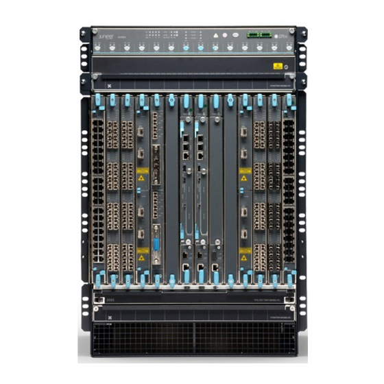
EX9214
IN THIS GUIDE
Step 1: Begin | 1
Step 2: Up and Running | 9
Step 3: Keep Going | 12
Step 1: Begin
IN THIS SECTION
Install the Large Mounting Shelf in an Open-Frame Rack | 3
Mount the EX9214 | 4
Connect Power to the EX9214 | 5
To install and perform initial configuration of a Juniper Networks EX9214 Ethernet Switch, you need:
One large mounting shelf (provided)
Mounting screws. The following mounting screws are provided:
Eight 12-24, ½-in. screws to mount the large mounting shelf on the rack
Sixteen 10-32, ½-in. screws to mount the switch on the rack
Two ¼-20, ½-in. screws to attach the grounding cable lug to the switch
Phillips (+) screwdrivers, numbers 1 and 2 (not provided)
7/16-in. (11-mm) torque-controlled driver or socket wrench (not provided)
One mechanical lift (not provided)
Advertisement
Table of Contents

Related Manuals for Juniper EX9214


Summary of Contents for Juniper EX9214
- Page 1 Mount the EX9214 | 4 Connect Power to the EX9214 | 5 To install and perform initial configuration of a Juniper Networks EX9214 Ethernet Switch, you need: One large mounting shelf (provided) Mounting screws. The following mounting screws are provided: Eight 12-24, ½-in.
- Page 2 Electrostatic discharge (ESD) wrist strap with cable (provided) 2.5-mm flat-blade (–) screwdriver (not provided) Power cord with a plug appropriate for your geographical location for each power supply (not provided) Ethernet cable with an RJ-45 connector attached (provided)
- Page 3 RJ-45 to DB-9 serial port adapter (provided) Management host, such as a PC, with an Ethernet port (not provided) Install the Large Mounting Shelf in an Open-Frame Rack Before front-mounting the router in an open-frame rack, install the large mounting shelf on the rack. The following table specifies the holes in which you insert screws to install the mounting hardware in an open-frame rack (an X indicates a mounting hole location).
- Page 4 2. Ensure that the rack is properly secured to the building in its permanent location. Ensure that the installation site allows adequate clearance for both airflow and maintenance. For details, see the Complete Hardware Guide for EX9214 Switches. 3. Ensure that the mounting shelf is installed to support the weight of the switch.
- Page 5 13. Connect the ground wire to the grounding points. 14. Reinstall the switch components. Ensure that all empty slots are covered with a blank panel. Connect Power to the EX9214 IN THIS SECTION Connecting EX9214 to AC power | 6 Connecting EX9214 to DC power | 7...
- Page 6 This procedure requires at least two AC nominal 220 VAC 20 amp (A) power cords. See the AC Power Cord Specifications for the EX9214 Switches to identify the power cord with the type of plug appropriate for your geographical location.
- Page 7 Power supply ejectors Grounding points ESD point Connecting EX9214 to DC power For each power supply: WARNING: Ensure that the input circuit breaker is open so that the cable leads will not become active while you are connecting DC power.
- Page 8 Cable with low resistance (indicating a closed circuit) to chassis ground is RTN. CAUTION: You must ensure that power connections maintain the proper polarity. The power source cables might be labeled (+) and (–) to indicate their polarity. There is no standard color coding for DC power cables.
-
Page 9: Step 2: Up And Running
For information about connecting to DC power sources, see DC Power Supply Electrical Specifications for the EX9214 switch. 12. Verify that the INPUT 0 OK or INPUT 1 OK LEDs on the power supply are lit green steadily. If using two feeds, verify that both INPUT 0 OK and INPUT 1 OK LEDs on the power supply are lit steadily. -
Page 10: Perform The Initial Configuration
Perform the Initial Configuration Configure the software: 1. Login as a root user. 2. Start the CLI and enter the configuration mode. root# cli root@> configure [edit] root@# 3. Set the root authentication password. [edit] root@# set system root-authentication plain-text-password New password: password Retype new password: password You can also set an encrypted password or an SSH public key string (DSA or RSA) instead of a clear-text password. - Page 11 root@# set system domain-name domain-name 8. Configure the IP address and prefix length for the Ethernet interface on the switch. [edit] root@# set interfaces fxp0 unit 0 family inet address address/prefix-length 9. Configure the IP address of a DNS server. [edit] root@# set system name-server address 10.
-
Page 12: Safety Warnings Summary
Power Cable Warning (Japanese) | 13 Contacting Juniper Networks | 13 See the complete EX9214 documentation at https://www.juniper.net/documentation/product/en_US/ex9214. Safety Warnings Summary This is a summary of safety warnings. For a complete list of warnings, including translations, see the EX9208 documentation at https://www.juniper.net/documentation/product/en_US/ex9208. -
Page 13: Power Cable Warning (Japanese)
For technical support, see: http://www.juniper.net/support/requesting-support.html Juniper Networks, the Juniper Networks logo, Juniper, and Junos are registered trademarks of Juniper Networks, Inc. in the United States and other countries. All other trademarks, service marks, registered marks, or registered service marks are the property of their respective owners.
Need help?
Do you have a question about the EX9214 and is the answer not in the manual?
Questions and answers