Sartorius Cubis Series User Manual
Precision and analytical balances msu models
Hide thumbs
Also See for Cubis Series:
- User instructions (36 pages) ,
- Operating instructions manual (121 pages) ,
- Operating instructions manual (94 pages)
Table of Contents
Advertisement
Quick Links
Advertisement
Table of Contents

Related Manuals for Sartorius Cubis Series


Summary of Contents for Sartorius Cubis Series
- Page 1 User Manual Sartorius Cubis Series Precision and Analytical Balances MSU Models...
-
Page 2: Table Of Contents
Contents Contents Notes on Using This Manual..... . . 3 DKD Measurement Uncertainty....101 Second Tare Memory (Preset Tare) . -
Page 3: Notes On Using This Manual
Read the safety precautions carefully. This manual is part of the product. Keep it in a safe and easily accessible location. If the manual should be lost or misplaced, please contact Sartorius for a replacement or download the latest manual from our website: www.sartorius.com... -
Page 4: Safety Instructions
Installation note: The operator shall be solely responsible for any modifications to the equipment and for connecting any cables or equipment not supplied by Sartorius. Information on operational quality is available upon request from Sartorius. You should only use peripherals and options available from Sartorius. - Page 5 Do not open the balance housing. If the seal is broken, this will result in forfeiture of all claims under the manufacturer’s warranty. The device should only be opened by specialized personnel trained by Sartorius. Disconnect the balance from the wall outlet prior to moving the device.
-
Page 6: Intended Use
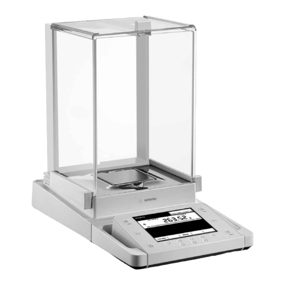
Safety Instructions Intended Use Cubis models are high-resolution precision and analytical balances. They were specially developed for exact determination of material mass in liquid, paste, powder, or solid form. Appropriate containers must be used for each type of sample material. Cubis models are designed specially for use in research, educational, and day-to-day laboratory tasks in science, technology, and industry. -
Page 7: Overview Of Equipment
Overview of Equipment Overview of Equipment Pos. Designation Upper draft shield panel/handle Rear panel Weighing pan Pan support (not for MSx225.../MSx125... models) Shield plate Pan retainer Right sliding panel/handle SD card slot (for MSU, MSA models) Leveling foot Display Display and control unit Draft shield/shield disk (only for models with a readability of 1 mg and 10 mg) Below-balance weighing port... -
Page 8: Getting Started
Getting Started Getting Started Unpacking the Balance Open the box. Use both hands to lift the balance, with the packaging, out of the cardboard box. Place the packaging with the balance on the floor. Remove the top part of the packaging. Cubis MSU User Manual... - Page 9 Getting Started Balance with Draft Shield Remove the packages (containing draft shield panels, weighing pan, pan sup- port, AC adaptor, etc.) from the lower packaging and place them to one side. Use both hands to lift the balance out of the packaging. Exercise caution to avoid glass breakage.
-
Page 10: Equipment Supplied
Getting Started Equipment Supplied After unpacking the device and all parts, check it immediately for any visible damage as a result of rough handling during shipment. If you detect any damage, proceed as directed in Section “Care and Maintenance” under “Safety Inspection”. Save the box and all parts of the packaging for any future transport. - Page 11 Getting Started Assembly Installing the Analytical Draft Shield; Balance Assembly (Draft Shield Identification: DA, DI, and DU) Fit parts onto the balance as shown in the picture. 1. Shield plate 2. Pan support (not for MSx225.../MSx125... models) 3. Weighing pan Slide the upper draft shield panel into the guide rails from the rear.
- Page 12 Getting Started Installing the Draft Shield on Milligram Balances, Balance Assembly (Draft Shield Identification: DE) Fit parts onto the balance as shown in the picture. 1. Shield plate 2. Pan support 3. Weighing pan Assembly of Milligram Balances without Glass Draft Shield (DR Option): Balance Assembly Fit all components listed below onto the balance in the order given: 1.
- Page 13 Getting Started Slide the upper draft shield panel into the guide rails from the rear while pressing the locking tab. Slide the side draft shield panel into the guide rails from the rear while pressing the locking tab. 1. Right draft shield panel 2.
- Page 14 Getting Started Place the pan support diagonally and press down lightly. 1. Pan support Carefully turn the pan support clockwise until the two buttons engage. The pan support is now attached. 2. Insert the shield plate/draft shield. 3. Place the weighing pan on the pan support. y This completes the balance assembly.
-
Page 15: Moving The Balance
Getting Started Moving the Balance Moving the Balance over Short Distances Always use both hands to carry the balance. Lift it up evenly either from the front and back from the sides. Exercise caution to avoid glass breakage. Never lift and carry the balance by its draft shield. Storage and Shipping Conditions –... -
Page 16: Installation Instructions
– If the stated supply voltage or the plug design of the power cord does not comply with your country’s standard, please inform the nearest Sartorius representative or your dealer. –... - Page 17 Getting Started Analytical and precision balances: 1. Plug the DC power supply cable into the balance and tighten the threaded fitting. Semi-microbalances (MSx1225..., MSx125... models): 1. Plug the DC supply cable into the electronics module and tighten the threaded fitting. 2.
- Page 18 Getting Started Leveling the Balance, Setting the Level Indicator Leveling the balance compensates for slant or unevenness at the place of installation. The balance must be perfectly horizontal to ensure con- sistent, reproducible weighing results. All models are equipped with an electronic tilt angle detection feature.
-
Page 19: Anti-Theft Locking Device
Getting Started Equipment Downtime Press the A key to switch the equipment to standby mode when it will not be in use for a short period of time. For longer periods of time, the device should be disconnected from the power supply. - Page 20 Getting Started Modifying the Balance Setting Up the Display and Control Unit at the Place of Use The display and control unit can be removed from all models and set-up wherever desired to enable the operator to customize the work space. Removing the Retainer with the Display and Control Unit Remove all items (such as weights) from the draft shield.
- Page 21 Getting Started Remove the upper draft shield panel. Models with the analytical draft shield (left figure): 1. Press on the locking tab. 2. Remove the panel. Models with the milligram draft shield (right figure): 1. Press on the locking tab. 2.
- Page 22 Getting Started Replace the upper and side shield panel. 1. Upper draft shield panel 2. Right draft shield panel 3. Left draft shield panel Level the balance. Leveling the balance compensates for slant or unevenness at the place of installation. The balance must be perfectly horizontal to ensure consistent, reproducible weighing results.
- Page 23 Getting Started Remove the two retaining screws. Remove the display and re-insert both screws back into their holes. Carefully pull the cable connected between the display and control unit from the retainer. Determine the required cable length. Return the balance to an upright position and fit the parts onto the balance. 1.
- Page 24 Getting Started Semi-microbalances: Attaching the Display and Control Unit to the Electronics Module (MSx225.../MSx125... models) The display and control unit can also be attached to the electronics module if required for operation. Turn over the balance and place on a soft surface. Remove the connection cable from the cable channel: Remove two screws from beneath the weigh cell and detach the plate.
- Page 25 Getting Started tAttach the display and control unit to the electronics module: Reattach the two retaining screws. Open the slot for the connection cable on the electronics module: Remove two screws from beneath the electronics module and detach the plate. Connect the display and control unit to the electronics module: Plug in the connection cable.
-
Page 26: Below-Cell Weighing
Getting Started Below-Cell Weighing A port for a below-cell weighing hanger is located on the bottom of the balance. 1. Remove the hook for below-cell weighing from the clip on the bottom of the balance. 2. Push the cover of the below-cell weighing port to one side. 3. - Page 27 Getting Started Using the Cable Opening of the Draft Shield Models with an analytical draft shield have an opening for passing a cable (for example, for a temperature sensor) through to the interior of the weighing chamber. 1. Lift the locking tab on the rear panel of the analytical draft shield. 2.
- Page 28 Getting Started Removing the Side Draft Shield Panels for Milligram Balances The side draft shield panels on milligram balances can be removed and stored at the back of the analytical draft shield. This can be useful, for example, when perform- ing continuous weighing or filling operations.
-
Page 29: Using The Balance
Getting Started Using the Balance Turning the Balance On/Off Make sure the balance has been installed and put into operation in accordance with the installation instructions. Press the on/off key A on the control unit. y The start screen appears briefly on the display, and then the user interface appears. -
Page 30: Using The Display And Control Unit
Using the Balance System Settings (MENU) contains all basic settings and parameters which used to operate the balance, affect the entire operation of the balance, and can also be used for creating new tasks. Wizard You can choose between two display types in several menus: The overview lists all parameters with their set options. -
Page 31: Setting The Language
Using the Balance Display and Control Unit The tilt angle of the display and control unit can be set as desired to enable optimal readability for changing working conditions. The color and brightness of the display can also be changed to match the illumination in the room. (see “User Management”... -
Page 32: Display In Operating Mode
Using the Balance Display The display varies depending on whether the application software is in operating mode or a menu is currently open (setup mode). Display in Operating Mode Function display: Current task (here: step 1 of 2) Verified balances feature the Metrology line: Left: weighing capacity (max);... -
Page 33: Display In Setup Mode
Using the Balance Display in Setup Mode Interactive area with instructions on how to proceed Orientation line showing your current location Working area with selectable options Toolbar with the available buttons Symbol indicating which menu (TASK, USER, or MENU) is currently open Scroll bar to view entire selection area Operating the Display Unit Equipment may be damaged by objects with points or sharp edges... -
Page 34: Activating/Switching Users
Using the Balance Entering Text and Numbers A keyboard will appear whenever you have to enter text and numbers. A cursor appears in the entry line above the keyboard. Select the character you would like to insert using the cursor softkeys. To accept the character, confirm with y The character will appear in the entry line. -
Page 35: System Settings (Menu)
System Settings (Menu) System Settings (Menu) This menu contains all balance settings relevant to the device. Basic settings can be made here that immediately affect the device. Changed settings do not affect previously defined tasks and user profiles. All system settings are applied to all user profiles. As long as a task is active and/or a user has been selected, several basic settings cannot be changed. -
Page 36: Level The Balance (Q-Level)
System Settings (Menu) Level the Balance (Q-Level) It is essential for exact weighing results that the balance is absolutely level. The front leveling feet can be used to level out small tilts in the floor. Depending on the model, the balance is equipped with either motorized or manually operated leveling feet. -
Page 37: Calibration/Adjustment Data
System Settings (Menu) Calibration/Adjustment Data Settings are divided into the following submenus: – Define calibration/adjustment functions – Define external calibration weights – Set fully autom. adjustment function isoCAL Configure the settings for all submenus. To save the settings, select Save Factory settings are marked with an asterisk (*). -
Page 38: Configure Timer Controlled Actions
System Settings (Menu) Configure Timer Controlled Actions You can program the following actions so that they run automatically at preset times: – Show message and execute command (see example below) – Execute command – Show message (e.g., a prompt as a reminder) The available actions are displayed. - Page 39 System Settings (Menu) Enter the text you want to be displayed when the action is being performed (e.g., “Timer-controlled adjustment”). Enter the time when the action should be performed for the first time. Define the time interval at which you want the action to be repeated (e.g., one day for daily occurrence).
-
Page 40: Device Information
System Settings (Menu) The programmed action is displayed in the list of actions. You can edit them again at any time here. Device Information You can view various information here. Select the information that you want to view. Display Device Information Here you can find all information about the manufacturer, model, serial number, host name, and IP address used. -
Page 41: View Alibi Data
System Settings (Menu) View Alibi Data The alibi memory contains (stores) weighing results with date, time, and process number. This takes place every time a print job is requested [e.g., by pressing P]. Tare and input values are also saved. The alibi memory can therefore Print be used as a replacement for a log printer. - Page 42 System Settings (Menu) Search for Records in the Alibi Memory (by Date) Select the search function. y An overview appears on the display. Limit the search by selecting the year, month, or day. Select Next y The desired records are displayed. Using the buttons, you can view more data records from the Prev.
- Page 43 System Settings (Menu) y The desired data record appears on the display. Show Available Memory (Information about the Alibi Memory and Available Memory Space) All important status information for the alibi memory is shown here. You can view the percentage of memory space in use and an estimate of how many data records can still be stored.
-
Page 44: Device Parameters
System Settings (Menu) Device Parameters Here you can update the software and change the following device settings. Settings are applied to all user profiles. – Configure balance parameters – Configure data output – Set date/time – Configure display and control unit properties –... - Page 45 System Settings (Menu) Leveler Configuration (Q-Level) You can configure the leveling function here. Leveling Notice : Leveling prompt is disabled. Off, no indication : As soon as leveling is required, Display status Level me! appears and flashes. : As soon as leveling is required, Alarm message, leveling required Level me! appears and flashes.
- Page 46 System Settings (Menu) Configure Data Output (Print Parameters) Here you can configure all settings for printing and data output. Several of these settings depend on the interface configuration (see Section “Interfaces”). Factory settings are marked with an asterisk (*). In order to view detailed information about individual settings, select Info. : Options: COM A, B, C (file/SD memory card), D Printout interface : Options: Print / SBI / xBPI / Web services / SICS / Second display.
- Page 47 System Settings (Menu) Ports (Configure Ports and Network Settings) Here you can configure interfaces (serial ports and network) and settings for the network. A detailed description of the connection options and data interface ports can be found in Section Interfaces. Configure Serial Ports The available ports are displayed.
- Page 48 System Settings (Menu) Network Ports Setup (Ethernet) For more information on network operation, see “Network Interface” in Section Interfaces. Select operating mode for the network interface. (expanded Sartorius communication / (Sartorius standard No function xBPI protocol) / Printer output SICS protocol Select connection type.
- Page 49 System Settings (Menu) Select the connected hardware device or control function. During checkweighing, the control outputs have no function when set to: – Foot switch YPE01RC – Control inputs Configure the settings for the control inputs and outputs. Options: Off, no function / TARE key / PRINT key / Cal./Adj. key / Zeroing / Taring To save the settings, select Save...
- Page 50 System Settings (Menu) Restore Factory Settings You can reset all settings individually to the factory settings at any time. Use the cursor softkeys to navigate through the sub- Device parameters menu to Restore factory settings Mark any settings you wish to reset and select Next.
- Page 51 System Settings (Menu) Configure the automatic mode for the draft shield. : Automatic mode is off. Off, no function : The draft shield doors are closed in automatic mode Close -> function -> open while the function is executed, and then the doors re-open. : The draft shield doors are closed in automatic mode while Close >...
- Page 52 System Settings (Menu) Define how long an ionization routine should take. in seconds: 3 to 15 sec., *8 sec. Operating time Define the intensity of the ionization. Soft intensity Normal intensity Strong intensity Check and correct all settings as required. To save the settings, select Save Cubis MSU User Manual...
-
Page 53: Task Management
Task Management (TASK) Task Management In the Task Management menu (TASK), you can: – Start a task – Configure a new task – Edit an existing task (modify, copy, delete) For task configuration, there are numerous applications available, e. g., weighing, parts counting, calculation. -
Page 54: Using Applications With The Factory Settings
Task Management (TASK) Using Applications with the Factory Settings Each application comes with specific factory settings. If you want to apply these settings unchanged, you can do this quickly during configuration: Open Task Management and select Edit Select Create. y An application list is displayed. Select the application you want to assign to the new task. - Page 55 Task Management (TASK) The basic procedure for configuring a task is: 1. Create new task. 2. Select application. 3. Review all of the following prompts and configure your own settings as required. 4. Perform steps 2 and 3 for additional applications if you would like to combine multiple applications.
- Page 56 Task Management (TASK) Example: Creating a Task Open Task Management and select Edit y The list of options is displayed. To define a new task, select Create y The list of applications is displayed. Use the cursor softkeys to view all applications. Select the application you want to assign to the new task.
-
Page 57: Configuring Printouts
Task Management (TASK) Configuring Printouts You will be prompted for the printer settings with every new task you create and can modify them as each task requires. The options for printouts depend on the how the ports and their operating modes are configured. - Page 58 Task Management (TASK) Initial Printout Parameters when the Balance Is Delivered When the balance is first delivered, two ports are configured: The peripheral port (ComA) is configured for one printout; the USB port (ComB) is configured for data exchange with a PC via SBI protocol. Printout interface: Com A (peripheral port) and ComB (USB/PC) Protocol to Com A: Print (preset by the port configuration) Standard printout to ComA: Standard 1 (measured value only)
- Page 59 Task Management (TASK) Example Automatic Printout to Peripheral Port, Second Display Operating Mode At a preset interval, automatic printouts should be sent to the connected peripheral device as a second display. Printout interface: Com A (peripheral port) Protocol: Remote display (toggling to port configuration possible) SBI output: Automatic printout Criterion: Without stability, at stability, or after weight change Format: 22 characters (for applications)
- Page 60 Task Management (TASK) Print Events You can define one or several events that trigger a printout. The number of selectable print events depends on the selected application. Basic Weighing: PRINT key Starting a task End of task , after calibration/adjustment Calibration/adjustment result For calculating applications the following events are also possible: Initialization of an application...
- Page 61 Task Management (TASK) Automatic Tare after Printing Should the balance be tared automatically after each printout? Off, no tare On (automatic tare after print request) Settings for SBI Output SBI Output Mode How should SBI printout be printed? : Printout generated by pressing the PRINT P key or by ESC Single print command via the interface : Printout generated automatically in the weighing cycle...
-
Page 62: Combining Applications Into One Task
Task Management (TASK) Combining Applications into One Task You can combine applications that are saved in the balance into one task. The following rules need to be followed (see table below): – An application can only be combined with applications from different groups. –... -
Page 63: Executing Tasks
Task Management (TASK) Executing Tasks After all required settings have been configured, you can now start and execute a task. If you haven’t already done so, go to Task Management. y The task selection is displayed. Select the desired task. If the desired task is already marked (dark background and arrow on left), select Start... -
Page 64: Weighing
Task Management (TASK) Weighing Purpose: Weight determination within the scope of the device-specific weighing capacity (see “Specifications”) Combination options: Mass unit conversion, second tare memory, and individual identifiers (SQmin function, DKD measurement uncertainty) Configuring a Task: My Weighing Weighing without combining with any other application: The settings for Weighing are displayed. -
Page 65: Mass Unit Conversion
Mass Unit Conversion Mass Unit Conversion Purpose: The weight value can be displayed in up to a maximum of five different units in succession (see table below). However, the desired weight units must be assigned beforehand (1 through 5). Combination options: Second tare (SQmin function, DKD measurement uncertainty) Not all units can be selected on balances used for legal metrology. - Page 66 Mass Unit Conversion Configuring a Task: Mass Unit Conversion Select the desired number of units (max. 5) to be used to display the weighing results. Now you will be prompted to enter the display accuracy and weight units of all the desired units one by one. Select the (e.g., gram, kilogram, carat, pound) for the first unit.
- Page 67 Mass Unit Conversion Executing a Task: Mass Unit Conversion If you haven’t already done so, go to Application Management. y The task selection is displayed. Select the desired task. If the desired task is already marked, select Start Follow the instructions on the display. To change the displayed unit, select Toggle Select the unit to be used to display the weighing results.
-
Page 68: Sqmin Minimum Weighing
SQmin Minimum Weighing SQmin Minimum Weighing Purpose: This application is used to compare the measured weight value directly with the defined minimum sample quantity (SQmin = sample quantity minimum). This ensures that weighing results are within tolerances defined by your quality assur- ance system. - Page 69 SQmin Minimum Weighing Executing a Task: SQmin Minimum Weighing If you haven’t already done so, go to Application Management. y The task selection is displayed. Select the desired task. If the desired task is already marked, select Start When you start a task with the SQmin function, the defined SQmin value is shown on the display.
-
Page 70: Individual Identifiers
Individual Identifiers Individual Identifiers Purpose: You can define identifiers for the following print jobs: – Printout by pressing PRINT – Starting a task – End of task – Initialization (for calculating applications only) – Result (for calculating applications only) – Component (for logging applications only) –... - Page 71 Individual Identifiers In the example, a unique title has been defined for each identifier. Enter the desired value (text) for each identifier . Select the identifiers that can be entered for executing the task. Select whether or not the variable identifiers should be counted up automatically.
- Page 72 If the desired task is already marked, select Start The defined identifiers are displayed (cf. example above). Select Next The predefined lines are printed when the task starts: Company: Sartorius Street: Weender Landstr. City: Goettingen Place the sample on the weighing pan and press the PRINT key The identifier for the printout is displayed and can be changed if necessary.
-
Page 73: Density Determination
You can determine the density and volume of liquid, solid, or pasty materials. Combination options: Checkweighing, statistics, second tare, or individual identifiers Requirements: You require the Sartorius YDK01MS density determination kit or your own customer-specific set. The basic calculations for density determination are described at the end of this section. Features... - Page 74 Select the method that you want to use: buoyancy or displacement. Select the density kit you want to use. For measuring with the YDK kit YDK-xxx density kit from Sartorius: : If you want to use another kit Other density kit : If you do not want to use any kit.
- Page 75 Density Determination Configuring a Task: Determining Density of Liquid Select Determine density of liquid Select the measurement conditions. : Measurement takes place under standard laboratory Air density at 20° conditions (20°C room and material temperature). : If the measurement is to take place under deviating conditions. User input Enter the required values.
- Page 76 Density Determination Check all settings in the overview and change individual parameters as required. A message asks whether you would like to add another application. If required, select additional applications to be combined. Now you will be prompted to configure the weighing and printing functions. Check all settings and change as required.
- Page 77 Density Determination Calculation Basis for Density Determination The density determination application is based on the equations: Density of sample (ρ) ρ Density of buoyancy liquid Weight of sample in air Weight of sample in liquid (when determining liquid density, buoyancy and displacement) Weight of fill medium (for pycnometer) Weight of sample and fill medium (for pycnometer)
-
Page 78: Statistics
Statistics Statistics Purpose: Saving and statistical analysis of weight values and other calculated values. The values are generated as results: – Transaction counter – Sum of all values – Average value – Standard deviation – Lowest value (minimum) – Highest value (maximum) –... - Page 79 Statistics Define when the number of measurements (items) will be set. : The item number is defined beforehand. Enter fixed quantity : Enter the item number Quantity can be changed during the process when you execute the task. Define whether or not automatic taring should take place after storing the value.
- Page 80 Statistics Place the next sample on the weighing pan and select Next Continue with all other samples in the same way. You can remove each last value from the statistics by selecting Corr. During the task, you view the result at any time by selecting Calc.
-
Page 81: Calculation
Calculation Calculation Purpose: This application is used to calculate the weight value using an algebraic formula that you define yourself. You can define a fixed formula or one that you can change while carrying out the task. For balances used in legal metrology, follow the directions in Section “Executing Tasks.”... - Page 82 Calculation Enter a name for the event printout, e.g., “Area” (max.6characters). Define how many decimal points should be used for the results: none, *1 ... 7 digits Enter the unit to be used for the results (max. six characters, e.g., cm An overview of all settings is displayed.
- Page 83 Calculation Examples of Calculation Formulae 1) Determination of diameter for cylindrical bodies Definition: Diameter = 2 * V (W / (π * l * Rho)) with: V = Square root W = weight value in g π = 3.145 l = length of sample in cm Rho = density of sample in g/cm (e.g., 8.30000 g/cm Input: 2...
- Page 84 Calculation Executing a Task: Calculation If you haven’t already done so, go to Application Management. y The task selection is displayed. Select the desired task. If the desired task is already marked, select Start If you want to work with a variable formula, you can now enter or change the formula.
-
Page 85: Averaging
Averaging Averaging Purpose: This application is used for moving samples (e. g., live animals) and for weighing in unstable environments. A measurement cycle is automatically carried out with a defined number of measurements for each object to be weighed. The individual measurements are averaged, and this average is displayed as the result. - Page 86 Averaging Enter the range of instability for the start of the measurement: 0.1%, 0.2%, 0.5% ... *10% ... 50% from measured object This entry estimates the strength of the instability that is caused by the activity (e. g., animal movement). You can use the rough estimation or a more detailed estimation using percentages.
- Page 87 Averaging Define whether or not the weighing results should be calculated with an addi- tional factor and how this factor should be applied. No factor You must now enter this factor. Enter fixed factor: : You must enter this factor when Factor can be changed during process you execute the task.
- Page 88 Averaging Executing a Task: Averaging with Manual Start If you haven’t already done so, go to Application Management. y The task selection is displayed. Select the desired task. If the desired task is already marked, select Start If you are using a variable number of measurements, enter the desired number. If you are weighing live animals, place the container (cage) on the weighing pan and tare the balance.
- Page 89 Averaging Executing a Task: Averaging with Automatic Start If you haven’t already done so, go to Application Management. y The task selection is displayed. Select the desired task. If the desired task is already marked, select Start If you are using a variable number of measurements, enter the desired number. If you are weighing live animals, place the container (cage) on the weighing pan and tare the balance.
-
Page 90: Formulation
Formulation Formulation Purpose: This application is used to weigh while adding several components consecutively. The balance is tared automatically after each component. The weight values of all individual components as well as the total weighing results are recorded and can be logged. The weight values and the component counter are saved in pro- tected memory so that an interrupted formulation process can be continued after the balance has been turned off or after a power failure. - Page 91 Formulation For all formulations, the following applies: – The individual components can be stored manually or automatically (first reproducible value). – If automatic storage of values was selected, the minimum load is determined when the task is created. – After weighing the first component, the option is displayed.
- Page 92 Formulation Once you configure the components, define the unit: (Formulation 1) *Amount in weight unit (Formulations 2 and 3) Default in percent, sum = 100% (Formulations 4 and 5) Default in percent, sum <> 100% Select Next Enter the number of components. An overview of all settings is displayed (here, Formulation 2 as an example).
- Page 93 Formulation The evaluation is displayed as soon as all components of the formulation have been added and weighed. You can also see the complete list here using the cursorsoftkeys. To delete the last component, select Corr. To go to the parameter page, select Param.
-
Page 94: Weighing In Percent
Weighing in Percent Weighing in Percent Purpose: This application is used to determine the percentage share or the percentage difference of the sample related to a reference weight. Options: You can enter a fixed reference weight or a reference percentage. Combination options: Checkweighing, timer-controlled functions, totalizing, statistics, formulation, second tare, individual identifiers (SQmin function, DKD measurement uncertainty) - Page 95 Weighing in Percent Define which percent calculation should be used. Example: Weight value = 10 g, reference weight = 50 g : The result is the percentage share of the weight value of the reference *Residue weight (residue: weight value / reference weight * 100%; in this example: 20%) : The result is the percentage loss between the weight value and the reference Loss weight (loss: weight value - reference weight / reference weight * 100%;...
- Page 96 Weighing in Percent Executing a Task: Weighing in Percent If you haven’t already done so, go to Application Management. y The task selection is displayed. Select the desired task. If the desired task is already marked, select Start If required, enter the reference percentage (e. g., 100%) or the reference weight. Place the sample on the weighing pan.
-
Page 97: Timer-Controlled Functions
Timer-controlled Functions Timer-controlled Functions Purpose: This application is used to trigger individual balance functions automatically at a specific time or after specific time intervals. The trigger time or interval must occur within 24 hours (1 day). Options: You can select the following functions: - Acoustic signal - Hold display (freeze) - Automatic printout of the display value... - Page 98 Timer-controlled Functions Specify whether or not there should be an automatic restart after the timer-controlled function has been triggered. *Off , no restart The timer is restarted as soon as the On (restart automatically): timer-controlled function has been carried out. An overview of all settings is displayed.
-
Page 99: Totalizing
Totalizing Totalizing Purpose: Adding up weight values and calculating values. The weight values of all individual components are recorded and can be logged. The weight values and the component counter are saved in protected memory so that an interrupted totalization process can be continued after the balance has been turned off or after a power failure. - Page 100 Totalizing Define when the number of measurements (items) will be set. The quantity of items is defined beforehand. Enter fixed quantity: Quantity can be changed during the process Enter the quantity of items when you execute the task. Define whether or not automatic taring should take place after storing the value.
-
Page 101: Dkd Measurement Uncertainty
DKD Measurement Uncertainty DKD Measurement Uncertainty Purpose: This application is used to ensure that the measurement uncertainty is displayed dynamically so that it conforms to the data documented on the DKD calibration certificate. Requirements: The function can only be used when the balance has been prepared for this before- hand by a service technician. - Page 102 DKD Measurement Uncertainty An overview of all settings is displayed. Check all settings and change as required. A message asks whether you would like to add another application. If required, select additional applications to be combined. Now you will be prompted to configure the weighing and printing functions. Check all settings and change as required.
-
Page 103: Second Tare Memory (Preset Tare)
Second tare memory Second Tare Memory (Preset Tare) Purpose: This application is used to define the second tare value. As soon as a second tare value is used, appears on the display for the respective net value. Net1 Options: You can either use a weight value or enter a numerical value as a second tare value. Combination options: Mass unit conversion, individual identifiers (SQmin function, DKD measurement uncertainty) - Page 104 Second tare memory The stored weight value is displayed as the second tare value. is also Net 1 displayed next to the current weight value. To delete the tare memory, select Clr T1 Entering a Numerical Value as a Second Tare Enter the tare value for T1 (e.g., 20).
-
Page 105: Parts Counting
Parts Counting Parts Counting Purpose: This application is used to determine the number of objects which each have approximately equal weight. This saves you from having to count individual parts. Options: You can calculate or enter the piece weight of individual objects. Combination options: Checkweighing, timer-controlled functions, totalizing, statistics, formulation, mass unit conversion, second tare memory, individual identifiers (SQmin function,... - Page 106 Parts Counting Define the accuracy to be used for the weight value. : As displayed *Normal resolution With one decimal place more than on the display 10-fold (+ 1 dec. place): With two decimal places more than on the display 100-fold (+2 dec.
- Page 107 Parts Counting The weight value for the reference objects is displayed. To determine the average piece weight, select Start The reference piece count and the average piece weight are displayed. You can now begin with the parts counting of unknown amounts. Place any amount of the objects on the weighing pan.
- Page 108 Parts Counting Executing a Task: Parts Counting by Entering the Piece Weight If you haven’t already done so, go to Application Management. y The task selection is displayed. Select the desired task. If the desired task is already marked, select Start The last used piece weight wRef is displayed.
-
Page 109: Checkweighing
Checkweighing Checkweighing Purpose: This application is used to check a weight value using preset control values. Options: Control values can be exact target values or tolerance range limit values within which the check value must lie. The check results are shown on the display. They can also be used for further electronic editing by activating the control ports at the data output. - Page 110 Checkweighing Define how the ports should be activated depending on the check results *Ports not active : Ports are only activated when the results Within checkweighing range are within the checkweighing range. The ports are always activated with each weight value. Ports always activated: : The ports are only activated When stable and in checkweighing range...
- Page 111 Checkweighing Executing a Task: Checkweighing If you haven’t already done so, go to Application Management. y The task selection is displayed. Select the desired task. If the desired task is already marked, select Start Define check values by entry: Select the input field Setp and enter the target. Select the input field Min or Max and enter the minimum or maximum check values.
- Page 112 Checkweighing The weighing result is displayed. It is also possible to see the weighing result on a graphic scale for a set target range. It can be seen immediately on the graphic scale if the result is outside of the tolerance. To switch the display to check mode, select Check The display will now show whether the weighing result has gone over upper...
-
Page 113: Importing/Exporting Data
Import/Export Data Importing/Exporting Data You can use an SD memory card to move and exchange data (import/export). This card is required when you want to save data externally or when you want to exchange data with other balances. For example, you can easily copy user pro- files to several balances. - Page 114 Import/Export Data Select the menu item. Import/export data Insert the SD card into the slot as shown in the picture. Select whether you wish to export or import data. Export Mark the data you wish to export and select Next Edit the name of the export folder, if desired, and select Next.
- Page 115 Next All previous data will be saved in the new format. Check your settings after importing the data (Menu, TASK, and USER). If the XML files continue to cause problems, contact your local Sartorius Service Center. Cubis MSU User Manual...
-
Page 116: Calibration And Adjustment
Calibration/Adjustment Calibration and Adjustment Background During calibration, a calibration weight is used to determine how much the displayed value deviates from the actual measurement value. This deviation is compared with an entered target value and is then eliminated by a subsequent adjustment of the balance. -
Page 117: Calibration/Adjustment Using External Calibration Weight
Calibration/Adjustment y The procedure will be executed. Wait until calibration/adjustment has been completed. y The results are displayed after the procedure is completed. To return to operating mode, select Back. Calibration/Adjustment Using External Calibration Weight An external calibration weight is required for this function. Please note the tolerance of the calibration weight being used. - Page 118 Calibration/Adjustment y Lastly, the results are shown on the display. To return to operating mode, select Back Cubis MSU User Manual...
-
Page 119: User Management
User Management (USER) User Management You can configure the following settings in this menu: – Creating new user profiles (only possible as administrator) – Editing user profiles (modify, copy, delete, change and delete passwords, depending on user rights) – Activating users User Management The user administration allows for defining of users with distinct sets of rights: the administrator and multiple users. - Page 120 Step 1: Select Language Select the desired language. Additional languages can be downloaded from the Sartorius “Cubis” website (e. g., Chinese or Croatian). To import these languages to the balance, see Importing Data in Section “System Settings.”...
- Page 121 The adminis- trator can remove the password protection so that a new password can be set, if desired. If the administrator forgets the password, please contact your Sartorius Service Center. Step 7: Check All Settings To see all settings, page down with the cursor softkeys.
-
Page 122: Activating Users
User Management (USER) y The program switches to user selection. The newly created user profile is placed at the end of the list. If you would like to activate the new user profile, select it here. y The program switches to the operating mode and the selected user is activated. To create additional user profiles, select and repeat the procedure Edit... -
Page 123: Editing User Profiles
User Management (USER) Editing User Profiles If you have not already done so, open the User Management menu by touching the USER H key. To open the menu for editing profiles, select from the user selection Edit screen. y The selection of edit functions is displayed. Which options for editing user profiles are available depends on whether or not you have administrator rights. - Page 124 User Management (USER) Deleting User Profiles This function can only be carried out by an administrator. Select Delete y All available user profiles are displayed. Mark each profile that you wish to delete and select Next To delete all profiles, select y All profiles selected for deletion are displayed in a security prompt.
-
Page 125: Interfaces
For data exchange, the interfaces are configured with the following protocols: – Printer output – SBI (Sartorius Balance Interface): Sartorius standard protocol for output to a PC or control unit. This simple ASCII-based protocol allows you to use ESC commands from your PC to control the basic weighing functions. –... -
Page 126: Usb Port (Pc)
Interfaces USB Port (PC) Purpose Any Cubis balance can be connected to a PC equipped with a USB port. A virtual serial interface (virtual COM port) is set up as a device type at the USB port. This virtual serial interface is identified und operated by the application program. The protocols xBPI, SBI, and SICS can be transmitted via the USB port. -
Page 127: Ps2 Interfaces For Barcode Scanner Or Keyboard
Interfaces ® Open the setting for the USB serial port in the Windows Control Panel: – START > My Computer > Control Panel – System > Hardware > Device Manager Open the Connections submenu. Double-click on USB Serial Port. Select Port Settings > Advanced. Changing Latency Time Open the settings for the USB serial port, following the above instructions. -
Page 128: Interfaces (Rs-232) 25-Pin And 9-Pin
Interface: RS-232 cables purchased from other manufacturers often have incorrect pin assign- ments for use with Sartorius devices. Failure to do so may damage or destroy your weighing system and/or peripheral devices! Be sure to check the pin assignments before you connect cables purchased from other manufacturers. - Page 129 Interfaces Pin Assignment Chart for Connecting Peripherals Purpose: For Sartorius peripheral devices Female Interface Connector: 25-pin D-Sub (DB25S) with screw connection Required Male Connector (Recommended): 25-pin D-Sub, DB25S, with integrated shielded cable clamp and shield plate assembly (Amp type 826 985-1C) and fastening screws (Amp type 164...
- Page 130 Interfaces Wiring Diagram for 25-pin Interface Diagram for connecting a computer or other peripheral device to the balance using the RS-232/V24 standard and cables up to 15 m (50 ft.) long Do not connect any other pins to the cable connector of the balance! Waage Computer Stecker...
-
Page 131: Configuring Serial Ports
Interfaces Configuring Serial Ports The available ports are displayed. Select the port you want to configure. Configure all settings for this port. To save the settings, select Save Configuration Options for the Serial Ports The following operating modes are available for this port: –... - Page 132 Interfaces Configuration Options for Printer Output Operating Mode You can modify all settings for this operating mode depending on the configured printer type. – Printer type: YDP10-0CE YDP20-0CE YDP03-0CE Universal YDP04IS-0CEUV – Selected protocol: Hardware handshake – Baud rate: 300 to 19200 baud (*9600) –...
- Page 133 Interfaces Explanations for the Setting Parameters Selected Protocol/Handshake The SBI (Sartorius Balance Interface) has transmit and receive buffers. Data trans- mission can be operated with a hardware or software handshake. Hardware Handshake (CTS/DTR): With a hardware handshake (4-wire interface) protocol, the handshake is controlled via the CTS and DTR lines.
-
Page 134: Bluetooth ® Interface (Com C, Optional)
Interfaces Bluetooth ® Interface (COM C, Optional) How to assemble the Bluetooth ® module is described in the supplied installation instructions. In order to transmit data via the Bluetooth module, the interface must first be configured. ® Configuring the Bluetooth Interface If appropriate, toggle to the System Settings menu. - Page 135 Make sure that the printer to which you wish to connect is ready to operate. Select the as the device. Sartorius BT printer To establish the connection, select Scan The balance will now search for the Bluetooth device. This process may take time.
-
Page 136: Network Interface (Ethernet)
Interfaces Network Interface (Ethernet) Purpose This interface lets you integrate your balance into a TCP/IP-based network. System Requirements The person configuring the Ethernet interface should have basic knowledge of TCP/IP-base networks and network technologies in general. The Ethernet interface is connected to the local network via the RJ45 slot. Features Transfer rate: 10Mbs/sec (10BASE-T, Ethernet) and 100Mbs/sec... - Page 137 Interfaces Remove the cover plate (3). Insert the Ethernet cable plug (4) so that it clicks audibly into place. Reattach the cover plate (5). Turn the locking lever back to its locked position. Exercise caution to avoid glass breakage for models with a draft shield. Turn over the balance and place it on a soft surface.
- Page 138 Interfaces Configuring Network Operation (Ethernet) Preparation: Before you can start with the configuration, you will require some information about your network. Please contact your network administrator. The important question is whether your network supports DHCP or not. DHCP With DHCP, you can automatically link a (new) balance to an existing network without having to configure it manually.
- Page 139 Examples: For the connection type Balance = Server you only need to enter the local TCP port (e. g., for working with the Sartorius SartoCollect software for data communi- cation). For the connection type Balance = Client, you have to enter the server TCP port and the server IP address (e.
-
Page 140: Data Output
Interfaces Data Output You can define the data output parameter so that output is activated either when a print command is received or automatically synchronized with the display or at defined intervals (see application programs and autoprint settings). Data Output by Print Command The print command can be transmitted by pressing P or by a software com- mand (EscP). - Page 141 Interfaces Special Outputs Position 1 10 11 12 13 14 15 16 – – CR LF CR LF CR LF and only upon request with ESC w0 (no print command): CR LF CR LF Spaces A = C: Calibration/Adjustment AB = – –: Final readout Draft shield status (optional): A = H:...
- Page 142 Interfaces Data Output Format with 22 Characters When data is output in this format, ID codes with 6 characters will precede data with a 16-character format. These six characters identify the subsequent value. Normal Operation 1 2 3 4 5 6 7 8 9 10 11 12 13 14 15 16 17 18 19 20 21 22 K K K K K K + A A A A A A A A A E E E CR LF –...
- Page 143 Interfaces ID Code Character K Individual Identifiers The ID is based on model type, P-ID1 Print ID1 e.g., not all units and IDs are T-ID1 Task start ID1 available for balances used in legal I-ID1 Initialization ID1 metrology. R-ID1 Result output ID1 C-ID1 Component ID1 E-ID1 Evaluation ID1 Device Information, Basic Data...
- Page 144 Interfaces Totalizing ID Code Character K (Continued) nDef Default number of items Comp Weight value start Calculation Comp Current weight value Form Formula Number of the item Results using equations CompC Weight value start: calculat- Variable X ed components Variable Y CompC Current weight value: calcu- Variable a lated components...
-
Page 145: Data Input
Interfaces Data Input SBI Commands (Data Input Format) The computer connected via the data port can send control commands to the balance to control balance and application program functions. These control commands may have different formats and contain up to 26 charac- ters. - Page 146 Interfaces Overview of SBI Commands Format Command Action/Function Comments ESC P Print to the interface where the prompt originated Corresp. to menu, with/without stability ESC T “TARE“ key taring and zeroing ESC K Filter “Very stable conditions” ESC L Filter “Stable conditions” ESC M Filter “Unstable conditions”...
- Page 147 Assign/prompt for function of multiple softkey lines RM38 Activate RM36-assigned softkey lines RM39 Activate/deactivate RM30-assigned softkey functions Additional Sartorius commands Command Action/Function Send weight value at stability and store in alibi memory (with optional label) Execute application command Query parameter...
-
Page 148: Updating The Software
Purpose: To better serve our customers, Sartorius constantly improves its balance software. Sartorius makes the latest software versions available online so that you can quickly and easily remain up-to-date. Sartorius, however, makes no guarantee regarding the use of this software. - Page 149 All previous data will be saved in the new format. After updating your software, check your settings (Menu, TASK and USER). If the XML files continue to cause problems, contact your local Sartorius Service Center. After a version check is run, the versions of the current and the new software are displayed.
-
Page 150: Error And Status Messages
Error messages are shown on the display for two seconds or must be acknowledged by pressing a key. The error text provides direct suggestions on how to proceed. If the error cannot be resolved by following the suggestions, please contact Sartorius customer service. Cubis MSU User Manual... -
Page 151: Gpl License
The licensing conditions of the Free Software Foundation, Inc. are available in English on the included CD-ROM. You can purchase the GPL source text from Sartorius AG on CD under the VF no. VF 4043 for a shipping cost of ¤ 20.00. -
Page 152: Care And Maintenance
Care and Maintenance Care and Maintenance Service Regular servicing by a Sartorius technician will extend the service life of your balance and ensure its continued weighing accuracy. Sartorius offers its customers service contracts with regular maintenance intervals ranging from 1 month to 2 years. - Page 153 Care and Maintenance Carefully remove any sample residue/spilled powder using a brush or hand-held vacuum. If necessary, remove the weighing pan, shield plate, and pan support. 1. Weighing pan 2. Shield plate/draft shield 3. Pan support Clean parts with a cloth or brush. Then replace the parts.
- Page 154 Insulation resistance >7ΜOhm as measured with a constant voltage of at least 500 volts at a 500 kOhm load. The duration and number of checks should be determined by a qualified Sartorius service technician on site based on specific ambient and operating conditions (once a year as a minimum).
-
Page 155: Shipping The Balance
Shipping the Balance If repairs are required, use the original packaging to transport the balance. To ensure adequate protection for safe shipment, Sartorius products have been packaged to the extent necessary using environmentally friendly materials. Only the original packaging provides optimum protection for the equipment. - Page 156 Shipping the Balance Transporting the Parts (Large Analytical Draft Shield) Get the box ready for the individual parts of the balance. Get the foam and cardboard inserts ready. Place the flat foam pieces in the box. Place the other foam pieces in the box. Cubis MSU User Manual...
- Page 157 Shipping the Balance Place the panels in the packaging. 1. Place the upper draft shield panel into the packaging (handle upwards). 2. Place the side draft shield panel into the packaging (handle upwards). 3. Place the side draft shield panel into the packaging (handle downwards). Insert the front foam pieces into the box, wedging the panels into the back foam pieces.
- Page 158 Shipping the Balance Place the shield plate/draft shield into the opening. Close the box. Transporting the Parts (Small Analytical Draft Shield) Get the box ready for the individual parts of the balance. Get the foam pieces ready. Place the balance parts on top of each other. 1.
- Page 159 Shipping the Balance Slide the parts into the foam. Place the panels in the packaging. 1. Place the side draft shield panel into the packaging (handle downwards). 2. Place the side draft shield panel into the packaging (handle downwards). Place the foam piece in front of the parts. Place the package into the box.
- Page 160 Shipping the Balance Slide the shield plate into the packaging. Close the box. Place the box into the packaging. Place the top part on to the packaging. Insert the balance into the box with cushioning. Send the packaged balance. Cubis MSU User Manual...
-
Page 161: Disposal
Member States to collect electrical and electronic equipment and disposed of it separately from other unsorted municipal waste so that it may be recycled. In Germany and several other countries, Sartorius AG itself assumes responsibility for the return and conformant disposal of its electronic and electrical products. -
Page 162: Specifications
(IEC/EN60320-1/C14) for connection to the power supply Other data See label on the adaptor or the user manual on accompanying CD Balance Power supply Only via Sartorius adaptor 6971987 Input voltage 15 VDC, ± 5% Power consumption 15 W (max.) - Page 163 Specifications Model-specific Data Semi-microbalances 0.01 mg Model MSU225S MSU225P MSU125P Readability 0.01 0.01/0.02/0.05 0.01/0.1 Weighing capacity 60/120/220 60/120 Tare range (subtractive) – 220 – 220 – 120 Repeatability <±mg 0 to 60 g: 0.015 0 to 60 g: 0.015 0 to 60 g: 0.015 60 to 220g: 0.025 60 to 220g: 0.04 60 to 120g: 0.06...
- Page 164 Specifications Model-specific Data Precision balances Models MSU5203S MSU5203P MSU3203S MSU3203P Readability 1/2/5 1/10 Weighing capacity 5200 1200/2400/5200 3200 1010/3200 Tare range (subtractive) - 5200 - 5200 – 3200 – 3200 Repeatability <±mg 1 Linearity <±mg 5 Corner load (test load [g]) 2 (2000) 2 (2000) 2 (1000)
- Page 165 Specifications Model-specific Data Precision balances Models MSU623S MSU623P MSU323S Readability 1/2/5 Weighing capacity 150/300/620 Tare range (subtractive) – 620 – 620 – 320 Repeatability <±mg 0.7 1/2/4 Linearity <±mg 2 Corner load (test load [g]) 2 (200) 4 (200) 2 (200) Min.
- Page 166 Specifications Model-specific Data Precision balances Models MSU6202S MSU6202P MSU5202S MSU4202S Readability 10/20/50 Weighing capacity 6200 1500/3000/ 5200 4200 6200 Tare range (subtractive) – 6200 – 6200 - 5200 – 4200 <±mg 7 Repeatability 7/20/40 Linearity <±mg 20 Corner load (test load [g]) 20 (2000) 50 (2000) 10 (2000)
- Page 167 Specifications Model-specific Data Verified models with EC Type-Approval Certificate: Semi-microbalances 0.01 mg Model MSU225S-0CE MSU225P-0CE MSU125P-0CE Accuracy class* For verified models: EC Type-Approval Certificate D09-09-015, Type: MSX Scale interval d* 0.01 0.01/0.02/0.05 0.01/0.1 Weighing capacity max* 60/120/220 60/120 Calibration value e* Min.
- Page 168 Specifications Model-specific Data Verified models with EC Type-Approval Certificate: Precision balances Models MSU5203S-0CE MSU5203P-0CE MSU3203S-0CE MSU3203P-0CE Accuracy class* For verified models: EC Type-Approval Certificate D09-09-015, Type: MSX Scale interval d* 1/2/5 1/10 Weighing capacity max* 5200 1200/2400/5200 3.200 1010/3200 Calibration value e* Min.
- Page 169 Specifications Model-specific Data Verified models with EC Type-Approval Certificate: Precision balances Models MSU623S-0CE MSU623P-0CE MSU323S-0CE Accuracy class* For verified models: EG-Type-Approval Certificate D09-09-015, Type: MSX Scale interval d* 1/2/5 Weighing capacity max* 150/300/620 Calibration value e* Min. load min* Tare equalization range (subtractive) <...
- Page 170 Specifications Model-specific Data Verified models with EC Type-Approval Certificate: Precision balances Models MSU6202S- MSU6202P- MSU5202S- MSU4202S- Accuracy class* For verified models: EC Type-Approval Certificate D09-09-015, Type: MSX Scale interval d* 0.01 0.01/0.02/0.05 0.01 0.01 Weighing capacity max* 6200 1500/3000/ 5200 4200 6200 Calibration value e*...
-
Page 171: Balance Dimensions
Balance Dimensions Balance Dimensions Semi-microbalances with Motorized Draft Shield All dimensions are given in millimeters Cubis MSU User Manual... - Page 172 Balance Dimensions Semi-micro and Analytical Balances with Manual DU Draft Shield All dimensions are given in millimeters Cubis MSU User Manual...
- Page 173 Balance Dimensions Precision Balances with a Readability of 1 mg and Manual DE Draft Shield All dimensions are given in millimeters Cubis MSU User Manual...
- Page 174 Balance Dimensions Precision Balances with a Readability of 1 mg and Framed DR Draft Shield All dimensions are given in millimeters Cubis MSU User Manual...
- Page 175 Balance Dimensions Precision Balances with No Draft Shield All dimensions are given in millimeters Cubis MSU User Manual...
-
Page 176: Accessories
The brand name and logo for Bluetooth® wireless technology are owned by Bluetooth SIG Inc. The use of this brand name and trademark by Sartorius AG is under license. Other brand names and trade names belong to their respective owners. -
Page 177: Declarations Of Conformity
Body registered at the Commission of the European Community for performing such verification. The legal basis for Sartorius to perform the EC verification is EC Directive No. 2009/23/EC for non-automatic weighing instruments. This Council Directive has that has been in effect since January 1, 1993 within the EU. The further legal... - Page 178 Declarations of Conformity Cubis MSU User Manual...
- Page 179 Declarations of Conformity Cubis MSU User Manual...
-
Page 180: Ec Type-Approval Certificate
EC Type-Approval Certificate Cubis MSU User Manual... -
Page 181: Plates And Markings
Plates and Markings Cubis MSU User Manual... - Page 182 Plates and Markings Cubis MSU User Manual...
- Page 183 Plates and Markings Cubis MSU User Manual...
- Page 184 Sartorius AG. The status of the information, specifications, and illustrations in this manual is indicated by the date given below. Sartorius AG reserves the right to make changes to the technology, features, specifications and design of the equipment without notice. Status:...
Need help?
Do you have a question about the Cubis Series and is the answer not in the manual?
Questions and answers