Sartorius Cubis MCA Series Operating Instructions Manual
Micro balances
Hide thumbs
Also See for Cubis MCA Series:
- Operating instructions manual (126 pages) ,
- Operating instructions manual (92 pages) ,
- Operating instructions manual (94 pages)

Subscribe to Our Youtube Channel
Related Manuals for Sartorius Cubis MCA Series


Summary of Contents for Sartorius Cubis MCA Series
- Page 1 Operating Instructions Original Operating Instructions Cubis ® MCA Models Micro Balances 1000047994...
-
Page 3: Table Of Contents
Contents Contents 1 About these Instructions . . . . . . . . . . . . . . . . . . . . . . . . . . . . 5 4 .10 Displays in the Operating Display . - Page 4 17 Sartorius Service . . . . . . . . . . . . . . . . . . .
-
Page 5: About These Instructions
About these Instructions About these Instructions Scope These instructions are part of the device . These instructions apply to the device in the following versions: Device Model Ultramicrobalance and microbalance MCA10 .6S . . .-M | MCA2 .7S . . .-M | with motorized draft shield MCA3 .6P . -
Page 6: Target Groups
About these Instructions Target Groups These instructions are addressed to the following target groups . The target groups must possess the specified knowledge . Target group Knowledge and responsibilities User The user is familiar with the operation of the device and the associated work processes . -
Page 7: Safety Instructions
The actions described are addressed to the “User” target group . If individual actions must be carried out by other target groups or by Sartorius Service personnel: The qualification required will be indicated in the description of the action . -
Page 8: Proper Working Order Of The Device
Working on the Device’s Electrical Equipment Only Sartorius Service personnel may work on or modify the electrical equipment of the device . The device may only be opened by Sartorius Service personnel . 2.5.3 AC Adapter and Power Supply Cable Serious injury can result, e .g . -
Page 9: Accessories, Consumables, And Spare Parts
− Device malfunctions − Device failure Only use approved accessories, consumables, and spare parts supplied by Sartorius . Information on operational quality is available upon request from Sartorius . Only use accessories, consumables, and spare parts that are in proper working order . -
Page 10: Device Description
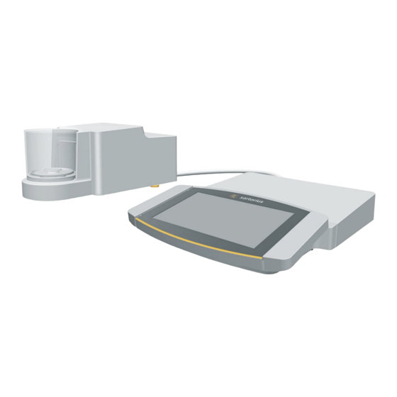
Device Description Device Description Device Overview Fig . 1: Microbalance with glass draft shield and electronics module (example) Pos. Designation Description Leveling foot Motorically adjustable Not depicted Manufacturer’s ID label Electronics module Operating display Touchscreen Palm-operated key Only for microbalance with motorized draft shield: Opens and closes draft shield . Control unit Weighing module Weighing chamber... -
Page 11: Draft Shield
Device Description Draft Shield Fig . 2: Microbalance with motorized glass draft shield and filter microbalance with manual metal ring draft shield (example) Pos. Designation Description Metal ring draft shield cover Made from metal, with handle, can be removed . Metal ring draft shield Consists of 2 metal rings that have been placed into each other with a side opening, can be rotated manually . -
Page 12: Weighing Pan And Associated Components
Device Description Weighing Pan and Associated Components Fig . 3: Microbalance with motorized glass draft shield and filter microbalance with manual metal ring draft shield (example) Pos. Designation Description Filter weighing pan Shield plate Connector For models MCA2 .7S . . . only Pan retainer Internal draft shield For models MCA2 .7S . -
Page 13: Connections On The Control Unit
Access switch Protects the device from changes to the device settings . Is sealed for conformity- assessed devices . Peripheral connection For connecting Sartorius accessories Weighing module connection For connecting the electronics module to the weighing module Power supply For connection to the power supply Cubis ®... -
Page 14: Displays On The Weighing Module
Device Description Displays on the Weighing Module Fig . 7: Displays on the weighing module (example) Pos. Designation Description LED strip Used for lighting of weighing chamber . The intensity of the lighting can be adjusted in the menu . When the control unit displays an error message: The LED strip is illuminated in orange . -
Page 15: Symbols On The Device
Device Description 3.10 Symbols on the Device Fig . 8: ID label on the device (example) Pos. Designation Description Manufacturer’s ID label Displays the metrological data of the device . Conformity-assessed models only Symbol Meaning During operation, parts in the device may be live . Only electricians may have access to and work on these parts, such as for maintenance and repairs . -
Page 16: Operating Concept
Operating Concept Operating Concept Operating Elements in the Main Menu Fig . 1: Operating elements in the main menu (example) Pos. Designation Description Navigation and function bar − Enables navigation, searching, filtering, and sorting in menus and lists . − In the “Settings” Menu: Displays the name of the menu . Available tasks Displays all tasks available for the active user . -
Page 17: Operating Elements In Task Management
Operating Concept Operating Elements in Task Management Fig . 2: Operating elements in Task Management (example) Pos. Designation Description Navigation and function bar − Enables navigation and searching in menus and lists . − Enables the addition of tasks . −... -
Page 18: Operating Elements In The Weighing Display
Operating Concept Operating Elements in the Weighing Display Fig . 3: Weighing display (example) Pos. Designation Description Application symbol Displays the symbol for the active application . Task name Displays the name of the active task . Date display Displays the current date . User name Displays the name of the active user profile . -
Page 19: Advanced Operator Guidance
Operating Concept Advanced Operator Guidance Advanced applications have advanced operator guidance . Fig . 4: Advanced operator guidance (example) Pos. Designation Description Weighing display with operator guidance Advanced operator guidance Guides the user through the active task . Includes 2 or 3 convertible displays depending on the selected application: −... -
Page 20: Messages
Operating Concept Messages Fig . 5: Error message (example) Pos. Designation Description Description Specifies the cause . Remedy Specifies the measures necessary to eliminate the cause of the message . Confirm Confirms and closes the message . Message type Indicates that the message is a status message, warning message, or an error message . -
Page 21: Status Center
Operating Concept Status Center Fig . 6: Status Center (example) Pos. Designation Description Messages Displays information, warning, and error messages . Leveling status Displays the status of the level . Status for the device Displays the general device information . Calibration and adjustment report Displays the data for the last and next adjustment and calibration . -
Page 22: Keypad
Operating Concept Keypad The keypad is used for entering values in entry fields . If an entry field is activated: The alphanumeric keypad or numerical keypad appears . Fig . 7: Alphanumeric keypad and numerical keypad (example) Pos. Designation Description Entry field Input assistance Indicates which values can be entered in the entry field, e .g . -
Page 23: Buttons In The Operating Display
Operating Concept Buttons in the Operating Display 4.9.1 Buttons for Navigation or Organization in Displays Pos. Symbol Designation Description [Menu] button Quits the active task and opens the main menu . [Back] button − Returns to the previous display . −... -
Page 24: Buttons For Editing Or Managing Entries
Operating Concept Pos. Symbol Designation Description [Error] button Opens the list of current error messages . [Info] button − Opens a display with additional information using the current menu . − In the Status Center: Opens the list of current status messages . [QAPP Center] button Opens the QAPP center . -
Page 25: Weighing And Print Function Buttons
Operating Concept Pos. Symbol Designation Description [Keypad] button Shows the keypad . [Lock] button Opens the entry field to change the password for the active user . 4.9.3 Weighing and Print Function Buttons Pos. Symbol Designation Description [Leveling] button Opens the Leveling Wizard . [isoCAL] button Starts the isoCAL function . -
Page 26: Displays In The Operating Display
Operating Concept Pos. Symbol Designation Description [Restart] button If an application is active: Deletes the saved values and restarts the application . [Report] button If an application is active, e .g . density determination: Displays a report about the progress of the application . [Result report] button If an application is active, e .g . -
Page 27: User Management
Operating Concept 4.11 User Management 4.11.1 User Profiles In the factory, 4 user profiles are created for the device . One role is assigned to each user profile . Each role has rights to operate the device . The rights assigned to each role depend on which device functions the user has to use . -
Page 28: Menu Structure
Service . Telephone number Display the telephone number for Sartorius Service . E-mail address Display the e-mail address for Sartorius Service . Technical hotline Display the technical hotline for Sartorius Service . Maintenance contact Display the responsible contact for maintenance measures . - Page 29 Operating Concept Level 1 Level 2 Level 3 Description Website Display the website for Sartorius Service . Alibi memory Display, filter, or browse the contents of the Alibi memory . Weigh range Ranges 1–4 Display the values for maximum load, minimum load, scale interval, and calibration step interval for weigh ranges 1–4 .
- Page 30 Operating Concept Level 1 Level 2 Level 3 Description Draft shield Left/right key Set the function of the left and right palm- operated keys . Only for devices with a motorized draft shield Sensor mode Set the operating mode for the sensor windows . Only for devices with a motorized draft shield Sensitivity range left sensor Define the sensitivity for the left sensor window...
- Page 31 Operating Concept Level 1 Level 2 Level 3 Description Connections Website for the balance Website Determines the settings for the display of the website for the device . Remote control display Define the settings for controlling the device remotely . Interfaces Serial transmission via Ethernet Display the profiles for the Ethernet connection .
-
Page 32: Navigating The Menus
Operating Concept 4.15 Navigating the Menus Procedure To open a menu from the main menu: Tap on the desired menu button in the function bar . The menu opens and the name of the open menu is displayed in the navigation bar . - Page 33 Operating Concept If elements from a display need to be filtered or a display needs to be browsed: Press the [Search] or [Filter] button . The keypad is displayed . Type the searched value or value to be filtered into the entry field (1) using the keypad .
-
Page 34: Installation
Installation Installation Scope of Delivery Item Quantity Device Weighing pan Filter Ultramicrobalances and Microbalances: Filter weighing pan For models MCA2 .7S . . .: Internal draft shield Shield plate For models MCA2 .7S . . .: Connector AC adapter For models with a motorized draft shield: Palm-operated key Country-specific power supply cable with test seal USB connection cable In-use dust cover for display and control unit... -
Page 35: Unpacking The Device
Installation Unpacking the Device Procedure Lift the device with the styrofoam padding out of the packaging . Place the device in the styrofoam padding on its side . Lift the styrofoam padding off the device . NOTICE Glass breakage due to incorrect handling of the device! Only lift the device by its base . -
Page 36: Procedure
Installation Procedure Turn the device on its side and place it on the soft support base . Unscrew both screws (2) from beneath the weighing module with the Torx Allen key . Lift out the cover plate (1) . Install a draft protection shield . Set up the device on the weighing table with recess . -
Page 37: Installing A Filter Balance With A Metal Ring
Installation Place the weighing pan (1) through the opening in the base of the weighing chamber into the pan retainer . To mount the weighing pan: Turn the weighing pan slightly while pressing down lightly . For devices with an internal draft shield: Place the internal draft shield on a shield plate . -
Page 38: Optimizing A Filter Weighing Pan With A Metal Ring Draft Shield For Left-Handed Users
Installation Insert the bearing pin (1) into the recess of the draft shield . Place the draft shield cover on the draft shield . 5.8.2 Optimizing a Filter Weighing Pan with a Metal Ring Draft Shield for Left-handed Users Requirements The metal ring draft shield has been mounted . -
Page 39: Installing Palm-Operable Keys
Installation 5.10 Installing Palm-operable Keys (Only for Devices with Motorized Draft Shield) For models with a motorized draft shield, 2 palm-operable keys can be installed . Procedure Affix both palm-operable keys (1) onto the side of the display and control unit . 5.11 Acclimatizing When a cold device is brought into a warmer area: The temperature difference can lead to condensation of humidity in the device (moisture formation) . -
Page 40: Getting Started
WARNING Severe injuries caused by using a defective power supply cable! Check the power supply cable for damage, e .g ., cracks in the insulation . If required: Contact Sartorius Service . Check whether the country-specific power plug matches the power connections at the installation site . -
Page 41: System Settings
System Settings System Settings Performing System Settings Default settings can be adjusted for the device and the applications in order to align with the ambient conditions and individual operating requirements . The following settings are necessary to operate the device together with connected components: −... -
Page 42: Parameter List
System Settings Parameter List 7.4.1 Parameters in the “User Configuration” Menu Parameters Configuration values Explanation Name User input Assign a name for the user . Description User input Enter a description for the user . User color Define a user color for the user . Language Set a language for the user . - Page 43 System Settings Parameters Configuration values Explanation Application filter Weighing (final readout)* Activates a filter that enables a fast change in the display for very fast load changes . Display changes with minimal load changes (in the digit range) occur more slowly .
- Page 44 System Settings Parameters Configuration values Explanation Available units The availability of units may depend on national legislation and is therefore country-specific . Multiple selection is possible . mg – milligrams* The device displays the weight in milligrams . g – grams* The device displays the weight in grams .
-
Page 45: Parameters In The "Device Settings" Menu
System Settings Parameters Configuration values Explanation Character memory Off* Deactivates the ID marking for the Alibi memory . Activates the ID marking for the Alibi memory . Name User input Assign a name for the report e .g . “YDP30” . Description User input Enter a description for the report (optional) . - Page 46 System Settings Parameters in the “isoCAL” Submenu Parameters Configuration values Explanation isoCAL function Deactivates the isoCAL function . This setting change is not available for all models . Info, manual execution If the device must be calibrated: The [isoCAL] button is displayed as the predominant button in the operating display .
- Page 47 System Settings Parameters Configuration values Explanation Left sensor Deactivates the sensitivity settings for the motion sensor . The left sensor field does not detect anything approaching . sensitivity range Short Sets the motion sensor response threshold to a low value: The left sensor field detects something approaching at a close distance .
- Page 48 Sets standby mode: The [Standby] button switches the device into standby long switch-on time mode . The device must be reactivated by pressing the ON key . Color scheme Sartorius Standard* Selects the color scheme for the “Sartorius Standard” operating display . * Factory setting Cubis ® MCA Operating Instructions...
-
Page 49: Parameters In The "Connections" Menu
Explanation Website Deactivates the display of the Sartorius Service website . On, without authentication* Sets the display options of the Sartorius Service website to “without authentication” . On, with authentication Sets the display options of the website for the device to “with authentication”... - Page 50 System Settings Parameters in the “USB-B connection” Submenu Parameters Configuration values Explanation Protocol Off* Deactivates the USB-B connection . Enables SBI communication . The data is output to a PC or control unit . Enables the use of ESC commands from a PC to control the basic balance functions with ASCII protocol .
- Page 51 System Settings Parameters in the “SBI Protocol” Submenu Parameters Configuration values Explanation Format Readout without identifier The data output only exports the measured value without ID . Readout with identifier* The data output exports the measured value with ID codes . Date/time and readout The data output exports the measured value, date, and time .
- Page 52 System Settings Parameters in the “Motion Sensor” Submenu (Only Where a Motion Sensor is Connected) Parameters Configuration values Explanation Number of gestures 2 gestures (left, right)* Activates the control of functions with 2 gestures . Gestures: left, right 4 gestures (left, right, up, Activates the control of functions with 4 gestures .
-
Page 53: Parameters In The "Device Maintenance
System Settings Parameters in the “External USB Switch” Submenu (Only Where an External USB Switch is Connected) Parameters Configuration values Explanation Key 1 pressed Execute / cancel taring The key starts a taring process or cancels a taring process . Key 1 released Key 2 pressed Key 2 released... -
Page 54: Operation
Operation Operation Switching the Device On and Off The device only delivers accurate values if it has reached the necessary operating temperature . The warm-up time after switching the device on must therefore be complied with . If the device is being switched on for the first time or if the device is switched on after being reset to factory settings: The Setup Wizard opens . -
Page 55: Leveling The Device
Operation Leveling the Device 8.3.1 Leveling the Device Leveling compensates any inclines at the device’s installation site . If leveling is necessary: The [Leveling] button appears in the weighing display and a message appears in the Status Center . Procedure If the weighing display is displayed: Press the [Leveling] button . -
Page 56: Defining The Opening Width
Operation 8.4.1 Defining the Opening Width It can be determined how far the draft shield should open when pressing the palm-operated key . The opening width of the draft shield can be determined separately for each palm-operated key . Procedure Same function Separate Function (one opening angle) -
Page 57: Adding An Application To A Task
Operation If an individual application from the displayed QAPP package is to be activated: Press the desired application . A display opens containing details about the selected application . Press the [License] button . The input field for the license key appears . If an additional cost is associated with the application: Enter the license key in the entry field and press the [OK] button . -
Page 58: Weighing
Operation Weighing NOTICE Chemicals may damage the device or accessories! Chemicals can attack the device or the connected accessories internally and externally . This may damage the device and accessories . Use appropriate containers when weighing chemicals . Procedure Start a task with weighing function . Zero the device . -
Page 59: Adjusting With The Isocal Function
Operation 8.10 Adjusting with the isoCAL Function The device can be automatically internally calibrated and adjusted using the isoCAL function . Requirements − The device is not located in the menu . − Alphanumeric inputs are not active . − The load on the weighing pan remains unchanged for 2 minutes . −... -
Page 60: Internally Calibrating And Adjusting The Device
Operation 8.11 Internally Calibrating and Adjusting the Device Requirements The weighing pan is unloaded . Procedure Open the main menu . Press the “Balance Adjustment” task . The internal calibration / adjustment function is executed . If automatic leveling is set for a model with motorized adjusting feet: The device levels itself automatically . -
Page 61: Marking Saved Values As Invalid
Operation 8.12.2 Marking Saved Values as Invalid Procedure Press the [Print Memory] button . The print memory opens and a list of all saved values is displayed . Press the [Edit] button . Press the desired items . An overview of all data to be printed is displayed for the selected items . Press the [Cancel] button . -
Page 62: Viewing The Alibi Memory
Operation 8.13 Viewing the Alibi Memory The Alibi memory stores weight values with date, time, and process number . The content of the Alibi memory can be searched and sorted using a filter . The Alibi memory has a ring buffer . This means that the oldest data records can be overwritten by new ones . -
Page 63: Running The "Statistics" Application
Operation 8.14.2 Running the “Statistics” Application The “Statistics” application saves up to 100 weight values and evaluates these statistically . The following values are saved and exported by the statistics application: − Number of components − Mean value − Standard deviation −... -
Page 64: Cleaning And Maintenance
Cleaning and Maintenance Cleaning and Maintenance Preparing the Device Procedure Turn the device off . Disconnect the device from the power supply . Open the draft shield . Cleaning the Device NOTICE Corrosion or damage to the device due to unsuitable cleaning agents! Do not use corrosive, chloride-containing, or aggressive cleaning agents . -
Page 65: Assembling And Connecting The Device
− The software update is saved on a USB mass storage device . Procedure Download the software update from the Sartorius website onto the USB mass storage device . If this relates to a zip file: Unzip the software update on the stick . -
Page 66: Performing A Qapp Center Update
− The QAPP center update is saved on a USB mass storage device . Procedure Download the QAPP center update from the Sartorius website onto the USB mass storage device . If this relates to a zip file: Unzip the QAPP center update on the stick . -
Page 67: Malfunctions
. control unit and the with the weighing module . weighing module . If the problem occurs again: 17, 78 Contact Sartorius Service . 10.3 Troubleshooting Fault Cause Remedy Chapter, page The operating display The device is disconnected . -
Page 68: Decommissioning
Decommissioning 11 Decommissioning 11.1 Decommissioning the Device Procedure Turn the device off . Disconnect the device from the power supply . Disconnect the device from all connected devices and all accessories, e .g . printer or electronics module . Clean the device (see Chapter 9 .2, page 64) . If below-balance weighing has been set up: Turn the device on its side and place it on a soft support base . -
Page 69: Storage And Shipping
.g . in the original packaging . Transport damage as well as measures for subsequent cleaning and disinfection of the device or device components by Sartorius shall be charged to the sender . WARNING Risk of injury due to contaminated devices! Devices contaminated with hazardous materials (NBC contamination) will not be accepted for repair or disposal . -
Page 70: Disposal
WARNING Risk of injury due to contaminated devices! Devices contaminated with hazardous materials (NBC contamination) will not be accepted by Sartorius for repair or disposal . 14.2 Disposing of Device and Parts 14.2.1 Information on Disposal The device and the device accessories must be disposed of properly by disposal facilities . -
Page 71: Technical Data
Filter weighing pan – d 50 Weight, approx . 7 .2 7 .9 15.2 Power Supply 15.2.1 Device Only by Sartorius AC adapter YEPS03-15V0 15.2.2 AC Adapter Unit Value Item No . YEPS03-15V0 Primary AC voltage 100 – 240 (±10 %) Frequency 50 –... -
Page 72: Safety Of Electrical Equipment
Technical Data Unit Value In operation °C 0 – +40 During storage and transport °C -20 – +80 Connector for mains connection according to IEC 60320-1 / C14: 3-pin Power supply cable Power supply cable according to IEC 60320-1 / C14: Country-specific, 3-pin, two-sided plug Other data: See label on AC adapter 15.2.3 Safety of Electrical Equipment... -
Page 73: Ambient Conditions
Technical Data 15.6 Ambient Conditions 15.6.1 Installation Site Unit Value Installation site Standard laboratory rooms Installation site according to IEC 60259-1, maximum altitude 3000 above sea level For indoor use only Temperature In operation °C +5 – +40 In operation for conformity-assessed devices: See information on the device’s ID plate During storage and transport °C... -
Page 74: Metrological Data
Technical Data 15.7 Metrological Data 15.7.1 Models MCA2.7S | MCA10.6S | MCA6.6S | MCA3.6P MCA2.7S MCA10.6S MCA6.6S MCA3.6P Unit Value Value Value Value Scale interval (d) µg 0 .1 1 | 2 | 5 Maximum capacity (Max) 2 .1 10 .1 6 .1 1 .1 | 2 .1 | 3 .1 Repeatability at 5 % load... -
Page 75: Isocal Function
Pin 8: Request to Send (RTS) Pin 9: Not assigned 15.11.2 Specifications for the USB-A Interface Communication: USB host (master) Connectable devices: Sartorius printers, USB sticks with software update 15.11.3 Specifications for the USB-B Interface Communication: USB device (slave) Type of interface: Virtual serial interface (virtual COM-port, VCP) and “PC direct”... -
Page 76: Accessories
1000 69Y03092 Display cable, 3 m, for separate installation of display On request and weighing units, installation by Sartorius Service or at the factory (order code VF4016) Installation of display cable, 3 m, for separate VF4016 installation of display and weighing units... -
Page 77: Hardware And Software For Pipette
Accessories 16.1.3 Hardware and Software for Pipette Calibration Item Quantity Order number Pipette calibration kit (hardware) for microbalance VF988 weighing modules 6 .6S and 3 .6P, consists of moisture trap and all required adapters 16.1.4 Filter Balance and Antistatic Accessories Item Quantity Order number... -
Page 78: Sartorius Service
Sartorius Service 17 Sartorius Service Sartorius Service is available for queries regarding the device . For information about the service addresses, services provided, or to contact a local representative, please visit the Sartorius website (www .sartorius .com) . When contacting Sartorius Service with questions about the system or in the event of malfunctions, be sure to have the device information, e .g . - Page 79 Conformity and Certificates Cubis ® MCA Operating Instructions...
-
Page 80: Certificate Of Compliance
Project: Date Issued: 70185847 2018-09-24 Issued to: Sartorius Lab Instruments GmbH & Co. KG Otto-Brenner-Strasse 20 Goettingen, Niedersachsen 37079 GERMANY The products listed below are eligible to bear the CSA Mark shown with adjacent indicators 'C' and 'US' for Canada and US or with adjacent indicator 'US' for US only or without either indicator for Canada only. - Page 81 Conformity and Certificates Certificate: 70185847 Master Contract: 167555 Project: 70185847 Date Issued: 2018-09-24 APPLICABLE REQUIREMENTS CSA Standards: CAN/CSA-C22.2 No. 61010-1-12 Safety Requirements for Electrical Equipment for Measurement, Control, and Laboratory Use, Part 1: General Requirements UL Standards: UL Std. No. 61010-1 (3 Edition) - Safety Requirements for Electrical Equipment for Measurement, Control, and Laboratory Use - Part 1: General Requirements...
-
Page 82: Fcc Supplier's Declaration Of Conformity
Connections between the device and peripherals must be made using shielded cables in order to maintain compliance with FCC radio frequency emission limits. Any modifications made to this device that are not approved by Sartorius may void the authority granted to the user by the FCC to operate this equipment. - Page 83 Sartorius Lab Instruments GmbH & Co. KG Otto-Brenner-Strasse 20 37079 Goettingen, Germany Phone: +49.551.308.0 www.sartorius.com The information and figures contained in these instructions correspond to the version date specified below. Sartorius reserves the right to make changes to the technology, features, specifications and design of the equipment without notice.
Need help?
Do you have a question about the Cubis MCA Series and is the answer not in the manual?
Questions and answers