Sartorius Cubis Series Operating Instructions Manual
Electronic semimicro, micro, precision and analytical balances
Hide thumbs
Also See for Cubis Series:
- User instructions (36 pages) ,
- User manual (184 pages) ,
- Operating instructions manual (94 pages)

Subscribe to Our Youtube Channel
Related Manuals for Sartorius Cubis Series


Summary of Contents for Sartorius Cubis Series
- Page 1 Operating Instructions Sartorius Cubis Series Electronic Semimicro, Micro, Precision and Analytical Balances MSE Models 1000025315...
-
Page 2: Table Of Contents
Contents Contents Notes on Using these Instructions � � � � � � � � � � � � � � � � 3 Menu Structure (Overview) � � � � � � � � � � � � � � � � � � � � 37 Safety Instructions �... -
Page 3: Notes On Using These Instructions
Read the Safety Instructions carefully� These instructions are part of the product� Keep them in a safe and easily accessible location� If the instructions should be lost or misplaced, please contact Sartorius for a replacement or download the latest version from our website: www�sartorius�com... -
Page 4: Safety Instructions
Note on Installation: The operator shall be solely responsible for any modifications to the equipment and for connecting any cables or equipment not supplied by Sartorius� Information on operational quality is available upon request from Sartorius� You should only use peripherals and options supplied by Sartorius�... - Page 5 Do not open the balance housing� If the seal is broken, this will result in forfeiture of all claims under the manufacturer’s warranty� The device may only be opened by specialized personnel trained by Sartorius� Disconnect the balance from the wall outlet prior to moving the device�...
-
Page 6: Intended Use
Safety Instructions Intended Use Cubis models are high-resolution balances� They were specially Cubis models are designed specially for use in research, developed for exact determination of material mass in liquid, education and day-to-day laboratory tasks in science and paste, powder or solid form� industry�... -
Page 7: General View Of The Equipment
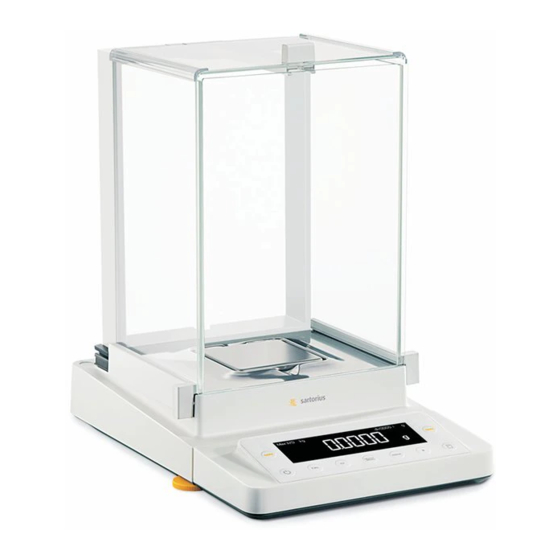
General View of the Equipment and Equipment Supplied General View of the Equipment and Equipment Supplied Analytical and precision balances with a weighing range of up to 15 kg Item Description Upper sliding draft shield panel/Handle Back panel Weighing pan Pan support (not for MSx225���/MSx125���... - Page 8 General View of the Equipment and Equipment Supplied Equipment Supplied and General View of the Equipment Balances with a weighing range of 20 kg or more Pos� Bezeichnung Pos� Bezeichnung DC jack USB interface for PC connection Leveling foot Display and control unit Level indicator Weighing pan Serial communications port (PERIPHERALS)
-
Page 9: Getting Started
Getting Started Getting Started Unpacking the Equipment Open the packaging at the top� Use both hands to lift the balance, with the packaging, out of the cardboard box� Place the packaging with the balance on the floor� Remove the top part of the packaging� Installation Instructions Select the proper setup location: –... - Page 10 Getting Started Balance with Draft Shield Remove the packages (containing draft shield panels, weighing pan, pan support, AC adapter, etc�) from the lower packaging and place them to one side� Use both hands to lift the balance out of the packaging� Exercise caution to avoid glass breakage�...
-
Page 11: Assembly
Getting Started Assembly Installing the Analytical Draft Shield Labeled DA, DI, and DU Assembling the Balance Fit parts onto the balance as shown in the picture� 1. Shield plate 2. Pan support (not for MSx225���/MSx125��� models) 3. Weighing pan Slide the upper draft shield panel into the guide rails from the rear� Slide the left and right draft shield panels into the guide rails from the rear�... - Page 12 Getting Started Installing the Draft Shield Labeled DE for Milligram Balances Assembling the Balance Fit parts onto the balance as shown in the picture� 1. Shield plate 2. Pan support 3. Weighing pan Assembly of Milligram Balances without Glass Draft Shield (DR Option): Balance Assembly Fit all components listed below onto the balance in the order given: 1.
- Page 13 Getting Started Slide the upper draft shield panel into the guide rails from the rear while pressing the locking tab� Slide the side draft shield panel into the guide rails from the rear while pressing the locking tab� y This completes the balance assembly� Remove the panel again if necessary 1.
- Page 14 Getting Started Carefully turn the pan support clockwise until the two buttons engage� The pan support is now attached� 2. Insert the shield plate/draft shield� 3. Place the weighing pan on the pan support� y This completes the balance assembly� Models with a Weighing Range from 20 kg Upwards: Place the weighing pan on the balance�...
- Page 15 Getting Started Connecting the Weigh Cell to the Electronics Module/Evaluation Unit MSE225…, MSx125: Connect the weigh cell and electronics module using the connection cable� Make sure that the connectors click into place so that both ends are securely connected� Please check the plug contacts to ensure a proper connection� There should be no tension on the connection cable�...
- Page 16 – If the stated supply voltage or the plug design of the power cord does not comply with your country’s standard, please inform the nearest Sartorius representative or your dealer� – The power connection must be made in accordance with the regulations applicable in your country�...
-
Page 17: Transporting The Balance
Getting Started Transporting the Balance Transporting the Device over Short Distances Exercise caution to avoid glass breakage� Never lift and carry the balance by its draft shield� Carry as shown in the illustration� Carry as shown in the illustration� Storage and Shipping Conditions –... -
Page 18: Power Connection
Getting Started Analytical and precision balances: 1. Plug the DC supply cable of the AC adapter into the power socket of the balance and tighten the threaded fitting� Balances with a readability of ≤ 0�01 mg 1. Plug the DC supply cable of the AC adapter into the power socket of the electronics module and tighten the threaded fitting�... -
Page 19: Warm-Up Time
Getting Started Leveling the Balance, Setting the Level Indicator Leveling the balance compensates for slant or unevenness at the place of installation� The balance must be perfectly horizontal to ensure consistent, reproducible weighing results� All models are equipped with an electronic tilt angle detection feature� If the balance is not level, a warning symbol is shown on the display�... -
Page 20: Anti-Theft Locking Device
Getting Started Connecting Electronic Devices (Peripherals) Make absolutely sure that the device is unplugged from the power supply before connecting/disconnecting any peripheral device (printer, scanner, PC) to or from the data port� A device connected to the power supply should never be opened� Anti-theft Locking Device (Accessory) Balances with a readability of ≤... -
Page 21: Modification Options
Getting Started Modification Options Setting Up the Display and Control Unit at the Place of Use The display and control unit can be removed for all models to enable the operator to customize the work space� Removing the Retainer with the Display and Control Unit Remove all items (such as weights) from the draft shield�... - Page 22 Getting Started Remove the upper draft shield panel� Models with the analytical draft shield (left illustration)� 1. Press on the locking tab� 2. Remove the panel� Models with the milligram draft shield (right figure): 1. Press on the locking tab� 2.
- Page 23 Getting Started Replace the upper and side shield panel� 1. Upper draft shield panel 2. Right draft shield panel 3. Left draft shield panel Level the balance� Leveling the balance compensates for slant or unevenness at the place of installation� The balance must be perfectly horizontal to ensure consistent, reproducible weighing results�...
- Page 24 Remove the two fixing screws using a screwdriver� Remove the control unit and re-insert both screws into their holes� Carefully remove the connection cable from its holder� y Long connection cables should only be installed by a Sartorius technician� Cubis MSE Operating Instructions...
- Page 25 Getting Started Semi-microbalances: Attaching the Display and Control Unit to the Electronics Module (MSE225..., MSE125... models) The display and control unit can also be attached to the electronics module if required for operation� Turn over the balance and place it on a soft surface� Remove the connection cable from the cable channel: Remove two screws from beneath the weigh cell and detach the plate�...
-
Page 26: Preparing Below-Cell Weighing
Getting Started Attach the display and control unit to the electronics module: Reattach the two retaining screws� Open the slot for the connection cable on the electronics module: Remove the screws from beneath the electronics module and detach the plate� Connect the display and control unit to the electronics module: Plug in the connection cable�... - Page 27 Use a suitable screwdriver to unscrew the cover plate from the bottom of the balance� Request the hook directly from Sartorius� The hook is available as an accessory� Install a draft protection shield� The below-cell weighing port may not be opened or used on balances used for legal metrology�...
-
Page 28: Using The Cable Opening In The Analytical Balance Draft Shield
Getting Started Using the Cable Opening of the Manual Analytical Balance Draft Shield Models with a manual analytical draft shield have an opening for passing a cable (for example, for a temperature sensor) through to the interior of the weighing chamber�... -
Page 29: Operation
Operation Operation Overview of Display and Control Panel Position Description Position Description Weight units Clear Function Calculated-value indicator: not a weight value This key is generally used to cancel functions: Tare – Quit application program symbol flashes: Balance is not level, leveling – ... -
Page 30: Basic Weighing Function
Operation Basic Weighing Function Features – Tare the balance – Print weight value Using a verified balance in legal metrology: The Type-Approval Certificate for verified balances is only valid for non-automatic weighing instruments� For automatic operation with or without additional, integrated equipment, please follow the applicable national regulations for the installation location�... -
Page 31: Leveling The Balance With The Inclination Sensor
Operation Level the Balance (Q-Level) It is essential for exact weighing results that the balance is absolutely level� The front leveling feet can be used to level out small tilts in the floor� An integrated sensor detects the alignment of the balance and triggers a warning message when leveling is required�... - Page 32 Operation Opening and closing the motorized draft shield (optional) If your balance is equipped with a motorized draft shield, you can use the * key to open and close the draft shield doors� Models with the analytical draft shield: The * key can be set, for example, so that it opens and closes the right and top door (for right-handed people)�...
-
Page 33: Calibration And Adjustment
– The sensitivity of the balance can be corrected a max� of 2%� – Adjustment with a Sartorius density determination kit YDK… is possible� – Balances with motorized leveling feet are leveled automatically prior to each new calibration/adjustment (menu setting: device: extras: level: auto.) If these settings are not made, the error message “Err 02"... - Page 34 Operation isoCAL*: automatic calibration and adjustment In the operating menu, select isocal-on� The balance will automatically display a flashing “isoCAL" character whenever the ambient temperature has changed since the last calibration|adjustment or a time interval has been exceeded� The balance wants to perform an automatic adjustment� The automatic internal calibration and adjustment prompt is activated when the following conditions have been met –...
- Page 35 Operation Internal Calibration/Adjustment External Calibration Configuration: Configuration: SETUP - Bal.Scal- CAL./ADJ. - Cal.Int. SETUP - Bal.Scal- CAL./ADJ. - Cal.Ext. The balance has a factory-set calibration weight value (see The balance housing has a built-in calibration/adjustment “Specifications”)� weight� Step Display/ § Select Calibration/Adjustment: (CAL) key Printout >...
-
Page 36: Configuration (Operating Menu)
Configuration (Operating Menu) Configuration (Operating Menu) You can configure the balance; i�e�, adapt it to individual requirements� Functions of the Keys in the Menu: Symbol displayed Key Function Scroll through menu items Select next item on current menu level (use right cursor to scroll through up to 4 menu levels) Confirm menu item ↵... -
Page 37: Menu Structure (Overview)
Configuration (Operating Menu) Menu Structure (Overview) Level 1 Level 2 Level 3 Info about Menu Level 1) Setup 1� 1� 1� Bal.Scal. Ambientconditions Balance parameters App.Filt. Application filter 1� 1� 2� Stab.Rng. Stability range 1� 1� 3� 1� 1� 4� STABILDLY� Stability delay 1�... -
Page 38: Parameter Settings: Overview
Configuration (Operating Menu) Parameter Settings: Overview ο = Factory setting √ = User-defined setting Info about Level 1 Level 2 Level 3 Level 4 Menu Level 1) Setup AMBIENT conditions (adapt filter) V.Stable Very stable 1� 1� 1� 1 BAL.SCAL. Balance 1� 1� 1� 2 ο... - Page 39 Configuration (Operating Menu) Level 1 Level 2 Level 3 Level 4 Info about Menu Level 2) device 2� 1� 1� 1 extras menu CAN EDIT (Additional Rd. Only Read only 2� 1� 1� 2 functions) Signal Acoustic Signal 2� 1� 2� 1 2�...
- Page 40 Configuration (Operating Menu) Info about Level 1 Level 2 Level 3 Level 4 Menu Level Periphery:/PC USB: 2) device 2� 2� 3� 3 / 2� 3� 3� 3 ο Odd peripher Parity Parity 2� 2� 3� 4 / 2� 3� 3� 4 pc-usb Even 2�...
- Page 41 Configuration (Operating Menu) Info for Level 1 Level 2 Level 3 Level 4 Menu level 4) App- 4� 1� WEIGH. Unit Toggle 4� 2� lic. Application programs ο Disp.dig. Display accuracy 4� 3� 1� 1 Counting resolut. 10 fold 10 times > disp� 4�...
- Page 42 Configuration (Operating Menu) Input: ID number, date and time Info about Level 1 Level 2 Level 3 Menu Level 5) Input ID input, max� 7 characters 5� 1� Input Possible characters: 0-9, A-Z, dash|hyphen and space Set date 5� 2� DATE Set time 5�...
- Page 43 Configuration (Operating Menu) Level 1 Level 2 Level 3 Level 4 Info about Menu Level Device-specific information 6) InFo Displays the software version 6� 1� Ver. no. 00-39-13 Info Displays the serial number 6� 2� Ser. no. 10801234 (to toggle between the upper/lower part of the display: press the S key) Displays the model ID 6�...
- Page 44 Configuration (Operating Menu) Setting the ID number, date and time Step Press key Display 1� Starting the Menu: S Hold Applic. 1� Display menu level 2� Select “Input” Input ID no.: 3� Select input for ID 2x V 4� Set or change ID number – 3------- With auto key repeat: S Press and hold...
-
Page 45: Application Programs
Application Programs Application Programs The following formula is used: All application programs can be selected on models verified for use in legal metrology� Density of sample = Verified values can be marked using the following characters: Weight in air – Percent ———————————————————————— ... - Page 46 Application Programs Density determination printout RhoFl 0.99823 o : Liquid density (g/cm 20.0 g : Weight in air : Weight in liquid 15.0 g : Result: Density of sample 4.0 o Table: Density values of H O at temperature T (in °C) T/°C 0�99973 0�99972...
- Page 47 Application Programs Parameter configuration: Applic. - Density - dec.plcs. -1 dec.pl. Example: Determining the density of a solid sample� The density at 20�0 degrees Celsius is 0�99823 g/cm � Step Press key Display/Printout 1� Attach sample holder and suspension wire 2� Tare the balance 0.0 g 3�...
-
Page 48: Counting
Application Programs Counting Preparation § Select the “Counting” application in the menu: see “Configuration” Display symbol: Z § Configuring parameters: Purpose With the Counting application, you can determine the Applic. Application programs number of parts which each have approximately equal Count. - Page 49 Application Programs Example: Counting parts of equal weight Parameter settings: Applic. - Count. Step Press key Display/Printout 1� Place the parts container + 22.6 g on the balance 2� Tare the balance 0.0 g 3� Place the reference sample quantity in the container (in this example: 20 units) 4�...
-
Page 50: Weighing In Percent
Application Programs Weighing in Percent Display symbol: % Purpose This application allows you to obtain weight readouts in percent which are in proportion to a reference weight� Changing the reference percentage value Activate function: Press the S key Select the desired reference quantity (1 to 100): In increments of one: Press the S key briefly In increments of ten: Press and hold the S key The selected percentage is saved to protected memory�... - Page 51 Application Programs Example: Determining residual weight in percent Parameter settings: Applic. - percent Reference percentage value: Ref 100% Step Press key Display/Printout 1� Tare the balance 0.0 g 2� Information: Enter the reference percentage ref 100 (Changing the reference: see the previous page) 3�...
-
Page 52: Calculation
Application Programs Calculation Display symbol: / Purpose With this application, you can calculate weight values using a multiplier or divisor� This can be used, for example, to determine the weight per unit area, or “gsm” weight (grams per square meter), of paper� Setting the Factor or Divisor Activate function: Press the S key... - Page 53 Application Programs Example: Calculating the weight per unit area of paper: An A4 sheet of paper is used in this example, with surface dimensions of 0�210 m + 0�297 m = 0�06237 m � To determine the weight per unit area, the total weight is divided by the surface� Parameter settings: Applic. - calc. - method - Divis.
-
Page 54: Animal Weighing/Averaging
Application Programs Averaging (animal weighing) Display symbol: V Purpose This application is used to determine the weights of unstable samples (e�g�, live animals) or to determine weights under very unstable ambient conditions� This requires an average to be calculated over several measurement cycles (also referred to as “subweighing operations”)�... - Page 55 Application Programs Example: Automatic weighing of animals with 20 subweighing operations Parameter configuration: Applic. - AnimalW. Step Press key Display/Printout 1� Place animal weighing bowl on the balance 22.6 g 2� Tare the balance 0.0 g 3� Change the number of subweighing operations ref 30 4�...
-
Page 56: Net-Total Formulation
Application Programs Net-total Formulation Display symbol: + Purpose This application can be used to weigh different components up to a defined total� You can print out both the total weight and the individual weights of the components� Features – Weigh up to 99 components from “0” to a defined total component weight� –... - Page 57 Application Programs Example: Counting parts into a container Parameter configuration: Applic. - Net.totl. Step Press key Display/Printout 1� Place empty container on the balance 65.0 g 2� Tare 0.0 g 3� Add first component + 120.5 g 4� Save component data 0.0 g Net Comp 1+ 120.5 g 5�...
-
Page 58: Totalizing
Application Programs Totalizing Display symbol: + Purpose This application can be used to add values from successive, mutually independent weight values to a total that exceeds the capacity of the balance� Features – Totalizing memory for up to 99 products –... - Page 59 Application Programs Example: Totalizing weight values Parameter configuration: Applic. - total - comp.prt: On Step Press key Display/Printout 1� Tare 0.0 g 2� Place sample on the balance (in this example: 380 g) + 380.0 g 3� Save the value to memory + 380.0 g Comp 1+ 380.0 g 4�...
-
Page 60: Mass Unit Conversion
Application Programs Mass Unit Conversion Purpose This application is used to change the weight value displayed from the basic weight unit to any of 4 application weight units (see table on next page)� Features – Set the basic unit and display accuracy in the Setup menu: See “Configuration�” –... - Page 61 Application Programs The balance can operate using the following units and display accuracies (in legal metrology, only units permitted by national law are available): Menu item Unit Conversion factor Symbol displayed Display accuracy 0) no Unit same as used 0) no (display accuracy in menu same as basic unit) under basic unit...
-
Page 62: Iso/Glp-Compliant Printout
Field for signature The ISO/GLP-compliant printout can have the following lines: Dash line -------------------- Configuration Date/Time (start of measurement) 17-Aug-2008 10:15 SARTORIUS Balance manufacturer Set the following menu items Balance type Mod. MSE8201S (Setup mode, see “Configuration”): Ser. no. 10105355 Balance serial number –... -
Page 63: Data Interfaces
For data exchange, the interfaces are configured with the following protocols: Printer output – SBI (Sartorius Balance Interface): Sartorius standard protocol for output to a – PC or control unit� This simple ASCII-based protocol allows you to use ESC commands from your PC to control the basic weighing functions�... - Page 64 Data Interfaces USB Port (PC) Purpose Any Cubis balance can be connected to a PC equipped with a USB port� A virtual serial interface (virtual COM port) is set up as a device type at the USB port� This virtual serial interface is identified und operated by the application program� The protocols xBPI and SBI can be transmitted via the USB port�...
- Page 65 Data Interfaces Installation Guides for Windows XP , Windows Vista and Windows 7 ® ® ® and Windows 8 ® Changing the Port Number If you use the USB interface with a program that limits the number of COM port designations (e�...
- Page 66 See “Configuration�” The many and versatile properties of these balances can be fully utilized for printing out records of the results when you connect your balance to a Sartorius data printer� The recording capability for printouts makes it easy for you to work in compliance with GLP�...
- Page 67 Data Interfaces Cabling Diagram 25-pin Interface Diagram for interfacing a computer or other peripheral device to the balance using the RS-232/V24 standard and cables up to 15 m (50 ft�) long Do not connect any other pins to the cable connector of the balance. Waage Computer Balance...
- Page 68 Data Interfaces Data Output You can define the data output parameter so that output is activated either when a print command is received or automatically synchronized with the display or at defined intervals (see application programs and autoprint settings)� Data Output by Print Command The print command can be transmitted by pressing P or by a software command (EscP)�...
- Page 69 Data Interfaces Special Outputs Position 1 10 11 12 13 14 15 16 CR LF � � Space High: Overload Cal� Ext�: Calibration, external Low: Underload Draft shield status (optional) Ionizer (optional) Y,Y,Y = Draft shield doors XXX = Decimal value calculated from binary data: Control information for models with normal draft shields Decimal value Binary value...
- Page 70 Data Interfaces Data Output Format with 22 Characters Here, the data output format with 16 characters is preceded by an ID code with a 6 characters� These six characters identify the subsequent value� Normal Operation 1 2 3 4 5 6 7 8 9 10 11 12 13 14 15 16 17 18 19 20 21 22 K K K K K K + A A A A A A A A A E E E CR LF –...
- Page 71 Data Interfaces Data Input SBI Commands (Data Input Format) The computer connected via the data port can send control commands to the balance to control balance and application program functions� These control commands may have different formats and contain up to 20 characters�...
- Page 72 Data Interfaces Overview of SBI Commands Format Command Action/Function Comments ESC P Print to the interface where the prompt originated Corresp� to menu, with/ without stability ESC T “TARE” key taring and zeroing ESC K Filter “Very stable conditions” ESC L Filter “Stable conditions”...
- Page 73 Interface: RS-232 cables purchased from other manufacturers often have incorrect pin assignments for use with Sartorius devices� Failure to do so may damage or destroy your weighing system and/or peripheral devices! Be sure to check the pin assignments before you connect cables purchased from other manufacturers�...
- Page 74 Data Interfaces Bluetooth® Interface (optional) How to assemble the Bluetooth® module is described in the supplied installation instructions� In order to transmit data via the Bluetooth module, the interface must first be configured� Configuring the Bluetooth® Interface Step Press key Display If necessary, toggle to the menu 1�...
-
Page 75: Error Codes
The weight readout is The balance was not calibrated/adjusted Adjustment obviously wrong Balance was not tared before weighing Tare If any other errors occur, contact your local Sartorius Service Center. Contact information: Please point your Internet browser to: http://www�sartorius�com Cubis MSE Operating Instructions... -
Page 76: Care And Maintenance
Care and Maintenance Service Regular servicing by a Sartorius technician will extend the service life of your balance and ensure its continued weighing accuracy� Sartorius offers its customers service contracts with regular maintenance intervals ranging from 1 month to 2 years�... - Page 77 Care and Maintenance Carefully remove any sample residue/spilled powder using a brush or hand-held vacuum� If necessary, remove the weighing pan, shield plate, and pan support� 1. Weighing pan 2. Shield plate/Draft shield 3. Pan support Clean parts with a cloth or brush� Then replace the parts�...
- Page 78 Care and Maintenance Cleaning the Weighing Chamber of Balances with a Readability of ≤ 1 µg Carefully remove any powdered sample material from beneath the shield disk using a small car vacuum cleaner with an mini-hose attached� Use blotting paper to remove any liquid sample material� Do not insert forceps or similar utensils behind the draft shield plate�...
- Page 79 Insulation resistance >7 MOhm as measured with a constant voltage of at least 500 volts at a 500 kOhm load� The duration and number of checks should be determined by a qualified Sartorius service technician on site based on specific ambient and operating conditions (once a year as a minimum)�...
-
Page 80: Transporting The Balance
Transporting the Balance If repairs are required, use the original packaging to transport the balance� To ensure adequate protection for safe shipment, Sartorius products have been packaged to the extent necessary using environmentally friendly materials� Only the original packaging provides optimum protection for the equipment�... - Page 81 Care and Maintenance Transporting the Parts (Large Analytical Draft Shield) Get the box for the individual parts of the balance ready� Place the bottom foam piece in the box� Place the panels in the packaging: 1) Place the upper draft shield panel into the packaging (handle upwards)� 2) Place the side draft shield panel into the packaging (handle upwards)�...
- Page 82 Care and Maintenance For small weighing pans: Place the shield plate into the box� Place the pan support and weighing pan into the opening� Close the box� For large weighing pans: Insert the following parts into the foam piece: 1) Pan support 2) Shield plate 3) Weighing pan Close the box�...
- Page 83 Care and Maintenance Transporting the Parts (Small Analytical Draft Shield) Get the box ready for the individual parts of the balance� Get the foam pieces ready� Place the balance parts on top of each other 1) Upper draft shield panel 2) Shield plate/draft shield 3) Pan support Slide the parts into the foam�...
- Page 84 Care and Maintenance Place the panels in the packaging� 1) Place one side panel into the packaging (handle downwards)� 2) Place the other side panel into the packaging (handle downwards)� Place the foam piece in front of the parts� Place the package in the box� Slide the shield plate into the packaging�...
- Page 85 Care and Maintenance Close the box� Place the box into the packaging� Place the top part on to the packaging� Insert the balance into the box with cushioning� The balance is now ready for transport� Cubis MSE Operating Instructions...
-
Page 86: Disposal
2) Select the “Services” tab� 3) Then select “Information on Disposal”� 4) Addresses for the local Sartorius disposal contacts can be found in the PDF files available for download on this page� Sartorius will not take back equipment contaminated with hazardous materials (ABC contamination) –... -
Page 87: Specifications
Two-sided plug with a 3-pin country-specific power plug and 3-pin socket (IEC/EN60320-1/C14) for connection to the power supply Other data See the power supply label Balance Power supply Only via Sartorius adaptor 6971987 Input voltage 15 VDC, ± 5% Power consumption 7 W (max�) Environmental conditions... - Page 88 Technical Specifications Model-specific Data Microbalances 0�001mg Model MSE6.6S MSE6.6S-F MSE3.6P Readability 0�001 0�001 0�001/0�002/0�005 Weighing capacity 6�1 6�1 1�1/2�1/3�1 Tare range (subtractive) -6�1 -6�1 -3�1 Repeatability 0�001 0�001 0�003/0�004/0�005 <±mg Linearity 0�004 0�004 0�004 <±mg Corner load (test load [g])*) µg 4 (2 g) 4 (2 g)
- Page 89 Technical Specifications Model-specific Data Semi-microbalances 0�01 mg Model MSE225S MSE225P MSE125P Readability 0�01 0�01/0�02/0�05 0�01/0�1 Weighing capacity 60/120/220 60/120 Tare range (subtractive) – 220 – 220 – 120 Repeatability <±mg 0 to 60 g: 0�015 0 to 60 g: 0�015 0 to 60 g: 0�015 60 to 220 g: 0�025 60 to 220 g: 0�04...
- Page 90 Technical Specifications Model-specific Data Precision balances Models MSE5203S MSE5203P MSE3203S MSE3203P Readability 1/2/5 1/10 Weighing capacity 5,200 1,200/2,400/5,200 3,200 1,010/3,200 Tare range (subtractive) – 5,200 – 5,200 – 3,200 – 3,200 Repeatability <±mg 1 Linearity <±mg 5 Corner load (test load [g]) 2 (2,000) 2 (2,000) 2 (1,000)
- Page 91 Technical Specifications Model-specific Data Precision balances Models MSE623S MSE623P MSE323S Readability 1/2/5 Weighing capacity 150/300/620 Tare range (subtractive) – 620 – 620 – 320 Repeatability <±mg 0�7 1/2/4 0�7 Linearity <±mg 2 Corner load (test load [g]) 2 (200) 4 (200) 2 (200) Optimal starting point of the measuring range*...
- Page 92 Technical Specifications Model-specific Data Precision balances Models MSE6202S MSE6202P MSE5202S MSE4202S Readability 10/20/50 Weighing capacity 6,200 1,500/3,000/ 5,200 4,200 6,200 Tare range (subtractive) – 6,200 – 6,200 – 5,200 – 4,200 Repeatability <±mg 7 7/20/40 Linearity <±mg 20 Corner load (test load [g]) 20 (2,000) 50 (2,000) 10 (2,000)
- Page 93 Technical Specifications Model-specific Data Precision balances Models MSE20201S MSE12201S MSE8201S MSE5201S Readability Weighing capacity 20,200 12,200 8,200 5,200 Tare range (subtractive) – 20,200 – 12,200 – 8,200 – 5,200 Repeatability <±mg 70 Linearity <±mg 200 Corner load (test load [g]) 300 (5,000) 200 (5,000) 200 (5,000)
- Page 94 Technical Specifications Model-specific Data Verified Models with EC Type Approval Certificate: Micro- and ultramicrobalances Model MSE6.6S-0CE MSE2.7S-0CE MSE3.6P-0CE Accuracy class* For verified models: EC Type Approval Certificate D09-09-015, Type: MSX Scale interval d* 0�001 0�0001 0�001/0�002/0�005 Weighing capacity max* 6�1 2�1 1�1/2�1/3�1 Calibration value e*...
- Page 95 Technical Specifications Model-specific Data Verified models with EC Type Approval Certificate: Semi-microbalances 0�01 mg Model MSE225S-0CE MSE225P-0CE MSE125P-0CE Accuracy class* For verified models: EC Type-Approval Certificate D09-09-015, Type: MSX Scale interval d* 0�01 0�01/0�02/0�05 0�01/0�1 Weighing capacity max* 60/120/220 60/120 Calibration value e* Min�...
- Page 96 Technical Specifications Model-specific Data Verified models with EC Type Approval Certificate: Precision balances Models MSE5203S-0CE MSE5203P-0CE MSE3203S-0CE MSE3203P-0CE Accuracy class* For verified models: EC Type-Approval Certificate D09-09-015, Type: MSX Scale interval d* 1/2/5 1/10 Weighing capacity max* 5,200 1,200/2,400/5,200 3,200 1,010/3,200 Calibration value e* Min�...
- Page 97 Technical Specifications Model-specific Data Verified models with EC Type Approval Certificate: Precision balances Models MSE623S-0CE MSE623P-0CE MSE323S-0CE Accuracy class* For verified models: EG-Type-Approval Certificate D09-09-015, Type: MSX Scale interval d* 1/2/5 Weighing capacity max* 150/300/620 Calibration value e* Min� load min* Tare equalization range (subtractive) <...
- Page 98 Technical Specifications Model-specific Data Verified models with EC Type Approval Certificate: Precision balances Models MSE6202S- MSE6202P- MSE5202S- MSE4202S- Accuracy class* For verified models: EC Type-Approval Certificate D09-09-015, Type: MSX Scale interval d* 0�01 0�01/0�02/0�05 0�01 0�01 Weighing capacity max* 6,200 1,500/3,000/6,200 5,200 4,200 Calibration value e*...
- Page 99 Technical Specifications Model-specific Data Verified models with EC Type Approval Certificate: Precision balances Modelle MSE12201S- MSE8201S- MSE5201S- MSE70200S- MSE36200S- Accuracy class* For verified models: EC Type-Approval Certificate D09-09-015, Type: MSX Scale interval d* 1,000 1,000 Weighing capacity max* 12,200 8,200 5,200 70,200 36,200...
-
Page 100: Dimensions (Balance Drawings)
Balance Dimensions Balance Dimensions Microbalances All dimensions are given in millimeters d 85 d 86.5 d 80 Cubis MSE Operating Instructions... - Page 101 Balance Dimensions Filter Microbalances All dimensions are given in millimeters d 106.5 d 84 Cubis MSE Operating Instructions...
- Page 102 Balance Dimensions Semi-microbalances All dimensions are given in millimeters Innenmaße Windschutz DA/DI Windshield inside dimensions 250 x 192 x Cubis MSE Operating Instructions...
- Page 103 Balance Dimensions Analytical Balances with a Manual DU Draft Shield All dimensions are given in millimeters Cubis MSE Operating Instructions...
- Page 104 Balance Dimensions Precision Balances with a Readability of 1 mg and Manual DE Draft Shield All dimensions are given in millimeters Cubis MSE Operating Instructions...
- Page 105 Balance Dimensions Precision Balances with a Readability of 1 mg and Framed DR Draft Shield All dimensions are given in millimeters Cubis MSE Operating Instructions...
- Page 106 Balance Dimensions Precision Balances with No Draft Shield and with a Weighing Range of up to 15 kg All dimensions are given in millimeters Cubis MSE Operating Instructions...
- Page 107 Balance Dimensions Precision Balances with No Draft Shield and with a Weighing Range of up to 20 kg All dimensions are given in millimeters Cubis MSE Operating Instructions...
-
Page 108: Accessories (Options)
Sartorius OPC Server for connecting all Sartorius Cubis ® balances Requires 32-bit Microsoft Windows 2000 or XP with current service packs� (free download of a 30-day trial version from the Sartorius website) – Initial license 6289OPC – Each additional license within an order... - Page 109 ® wireless technology are the property of Bluetooth SIG Inc� The use of this brand name and trademark by Sartorius AG is under license� Other brand names and trademarks are the property of their respective owners� Cubis MSE Operating Instructions...
-
Page 110: Ec / Eu Declaration Of Conformity
EC / EU Declaration of Conformity For verified balances, the conformity declaration supplied with the balance is valid for use in the EEA� Please retain this declaration� Cubis MSE Operating Instructions... -
Page 111: Fcc Supplier's Declaration Of Conformity
Connections between the device and peripherals must be made using shielded cables in order to maintain compliance with FCC radio frequency emission limits. Any modifications made to this device that are not approved by Sartorius may void the authority granted to the user by the FCC to operate this equipment. -
Page 112: Csa Certificate Of Compliance
CLASS - C872185 - ELECTRICAL EQUIPMENT FOR LABORATORY USE-Certified to US Standards Scale, CUBIS Series, CUBIS Ultra Micro Series, CUBIS High Capacity Series MSmxyz-u-v-c, MSmx.yz-u-v-c and MCMxywc (only High Capacity Series), rated 15Vdc (+20%,-10%), 7W Max. Scale, CUBIS Mass Comparator Series, MCMxy-c-d, MCMxKy-c-d or MCMx.y-c-d, rated 15Vdc (+20%,-10%), 7W Max Scale, CUBIS Pipette Calibration Series, MPSxyz-v-c or MPSx.yz-v-c, rated 15Vdc (+20%,-10%), 7W... - Page 113 CSA Certificate of Compliance 2070872 Master Contract: 167555 Certificate: 70084305 Date Issued: 2016-09-09 Project: versions or blank; w [up to two numbers and or letters] = type of display unit or blank; d=DAKKS or blank; the hyphens “-“ may be omitted. Notes: 1.
- Page 114 CSA Certificate of Compliance 2070872 Master Contract: 167555 Certificate: 70084305 Date Issued: 2016-09-09 Project: The following markings appear on the product: Submittor's identification (company name and/or file number and/or registered tradename); Marking on the unit that indicates the manufacturing location if the equipment is manufactured at more than one factory location.
-
Page 115: Ec Type Approval Certificate
EC Type Approval Certificate Cubis MSE Operating Instructions... -
Page 116: Plates And Markings
Plates and Markings Cubis MSE Operating Instructions... - Page 117 Plates and Markings Cubis MSE Operating Instructions...
- Page 118 Plates and Markings Cubis MSE Operating Instructions...
- Page 119 Plates and Markings Cubis MSE Operating Instructions...
- Page 120 Plates and Markings Cubis MSE Operating Instructions...
- Page 121 Sartorius Lab Instruments GmbH & Co. KG Otto-Brenner-Strasse 20 37079 Goettingen, Germany Phone: +49.551.308.0 www.sartorius.com The information and figures contained in these instructions correspond to the version date specified below. Sartorius reserves the right to make changes to the technology, features, specifications and design of the equipment without notice.
Need help?
Do you have a question about the Cubis Series and is the answer not in the manual?
Questions and answers