
Related Manuals for Sartorius Cubis MCE


Summary of Contents for Sartorius Cubis MCE
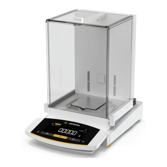
- Page 1 Operating Instructions Original Operating Instructions Cubis ® MCE Models Semi-micro-, Analytical and Precision Balances 1000041864...
-
Page 3: Table Of Contents
Contents Contents 1 About these Instructions . . . . . . . . . . . . . . . . . . . . . . . . . . . 6 4 Operating Concept . - Page 4 Contents 7.3.4 Parameters in the 10 Malfunctions . . . . . . . . . . . . . . . . . . . . . . . . . . . . . . . . . . . . . . 73 “Applications”...
- Page 5 17 Sartorius Service . . . . . . . . . . . . . . . . . . .
-
Page 6: About These Instructions
About these Instructions About these Instructions Scope These instructions are part of the device. These instructions apply to the device in the following versions: Device Model Cubis semi-microbalance, with MCE125P-... | MCE125S-... | ® manual or motorized draft shield, MCE225P-... | MCE225S-... with or without ionizer Cubis analytical balance, with... -
Page 7: Target Groups
About these Instructions Figures on the Operating Display The figures on the operating display of the device may deviate from those in these instructions. Target Groups These instructions are addressed to the following target groups. The target groups must possess the specified knowledge. Target group Knowledge and responsibilities User... -
Page 8: Safety Instructions
We recommend that any repair work, even that not covered by the warranty, is carried out by Sartorius Service or after consulting with Sartorius Service. Operating Instructions Cubis ®... -
Page 9: Personnel Qualification
A damaged device or worn parts may lead to malfunctions or cause hazards which are difficult to recognize. Only operate the device when it is safe and in perfect working order. Have any malfunctions or damage repaired immediately by Sartorius Service. Safety Information on the Device Symbols, e.g. -
Page 10: Electrical Equipment
Only use the original power supply cable and power supply. If the power supply or power supply cable must be replaced: Contact Sartorius Service. Do not repair or modify the power supply or power supply cable. Conduct in an Emergency If there is immediate danger of personal injury or if there is a risk of damage to the device, e.g., due to malfunctions or dangerous situations, the device... -
Page 11: Personal Protective Equipment
Safety Instructions Personal Protective Equipment Personal protective equipment protects against risks arising from the materials being processed. Missing or unsuitable personal protective equipment can result in injuries. If the workplace or process in which the device is being used requires personal protective equipment: Wear personal protective equipment. -
Page 12: Device Description
Device Description Device Description Device Overview Fig. 1: Semi-microbalance with motorized draft shield with ionizer and electronics module (example) Pos . Name Description Weighing chamber Manufacturer’s ID label Not depicted Weighing module Electronics module Only for semi-microbalances with electronics module Leveling foot Motorically adjustable Control unit... -
Page 13: Draft Shield
Device Description Draft Shield Fig. 2: Precision balance with frame draft shield, analytical balance with motorized analytical draft shield, and analytical balance with manual analytical draft shield (example) Pos . Name Description Frame draft shield Is placed on the draft shield. Analytical draft shield −... -
Page 14: Weighing Pan And Associated Components
Device Description Weighing Pan and Associated Components Fig. 3: Precision balances with frame draft shield, analytical balance with manual analytical draft shield, and precision balance with manual analytical draft shield (example) Pos . Name Description Weighing pan Pan support Only for models with pan support Shield plate Pan retainer Operating Instructions Cubis... -
Page 15: Connections And Components On The Weighing Module
9-pin, for connection to a PC or PLC Access switch − Protects the device from changes to the device settings. − Is sealed for conformity-assessed devices. Peripheral connection For connecting Sartorius accessories. Power supply For connection to the power supply Slot For attaching a “Kensington” anti-theft device Operating Instructions Cubis ®... -
Page 16: Connections And Components On The
Menu access switch − Protects the device from changes to the device settings. − Is sealed for conformity-assessed devices. Peripheral connection For connecting Sartorius accessories. Weighing module connection For connecting the electronics module to the weighing module Power supply For connection to the power supply Operating Instructions Cubis ®... -
Page 17: Connections On The Control Unit
Pos . Name Description USB connection Concealed, no function, for Sartorius Service only Safety Equipment 3.7.1 Protective Caps on the Analytical Balance and Precision Balance Fig. 8: Protective caps on the weighing module for the analytical balance and precision balance Pos . -
Page 18: Protective Caps On The Electronics
Device Description 3.7.2 Protective Caps on the Electronics Module Fig. 9: Protective caps on the electronics module Pos . Name Description Protective cap fo USB-A connection Plastic attachment hood, fastened to the device. Protective cap for USB-B connection Plastic attachment hood, fastened to the device. Protective cap for COM-RS232 connection Removable plastic sealing cap. -
Page 19: Symbols On The Device
Device Description Symbols on the Device Fig. 10: ID label on the device Pos . Name Description Manufacturer’s ID label Displays the metrological data of the device. Symbol Meaning During operation, parts in the device may be live. Only electricians may have access to and work on these parts, such as for maintenance and repairs. -
Page 20: Operating Concept
Operating Concept Operating Concept Operating Display in Weighing Mode Fig. 1: Operating display in weighing mode (example) Pos . Name Description Symbols for the selected application Weight value display In the selected basic unit. Metrological data Weight units Shows the selected basic unit, e.g. grams, [g]. Visual touch-feedback Visual note on an active button or key. -
Page 21: Operating Display In The Menu
Operating Concept Operating Display in the Menu Fig. 2: Operating display in the menu (example) Pos . Name Description Position in the 1st menu level Shows the position of the displayed menu or configuration value in up to 4 menu levels. Position in the 2nd menu level Position in the 3rd menu level Position in the 4th menu level... - Page 22 Operating Concept Symbol Name Description [Leveling] button Starts a leveling process. [GLP] button − Exits the GLP printout and starts printing the GLP footer. − If the “Net-total”, “Totalizing”, or “Statistics” application is active: Prints and deletes the saved values and exits the application. [Toggle between weight units] If the “Toggle between weight units”...
-
Page 23: Displays In The Operating Display
Operating Concept Displays in the Operating Display Symbol Name Description [Leveling] display − Indicates that the device is leveled. − If the center circle is flashing: Indicates that the device is not leveled. [Leveling] display Flashes while the device is leveling. [Counting] display Indicates that the “Counting”... -
Page 24: Menu Structure
Operating Concept Symbol Name Description [Quantity] Indicates that a quantity is being displayed. [Invalid weight value] display − Indicates that the display does not contain a weight value, rather it is the calculated result of an application, e.g. for the “Totalizing” application. - Page 25 Operating Concept Level 1 Level 2 Level 3 Description SETUP BALANCE DISP.DIG. − Define whether all decimal places are displayed. − A lower display accuracy enables a faster display. − The setting option is not available on conformity- assessed devices. CAL./ADJ. Define the function of the [Adjust] button.
- Page 26 Operating Concept Level 1 Level 2 Level 3 Description DEVICE D.SHIELD CONTROL Activate | deactivate the [Change] key for the “Draft shield” motorized draft shield. Only for devices IONIZER Only for devices with an ionizer: Define whether an with a motorized ionization process starts after closing the draft draft shield.
- Page 27 Operating Concept Level 1 Level 2 Level 3 Description DATA.OUTP. PRNT.PARA. ACTIVATE Define whether the printout or PC direct data “Data Printout and PC “Triggers” output takes place with or without balance stability. output” direct transfer FORMAT Define the format for the printout (characters per line). settings PRT.INIT.
- Page 28 Operating Concept Level 1 Level 2 Level 3 Description APPLIC. TAR./STAT. Activate | deactivate automatic taring for the “Applications” “Tare / statistics” “Statistics” application. UPDATE Start a firmware update. The menu is only available if a USB mass storage device is connected. INPUT ID NO.
-
Page 29: Navigating The Menus
Operating Concept Navigating the Menus Procedure To access the settings menu: Press the [Menu] button. To scroll through all menus in the same level: Press the [Up] or [Down] button. To switch to the displayed menu level: Press the [Confirm] button on the keypad. - Page 30 Operating Concept If an integer reference value needs to be selected in the reference value display (1) of a selected application, e.g. “Weighing in percent” or “Animal weighing” applications: Press the [Up] or [Down] button. This increases or decreases the reference value by 1.
-
Page 31: Installation
Installation Installation Scope of Delivery Item Quantity Device Weighing pan Shield plate For models with pan support: Pan support Power supply unit Country-specific power supply cable with test seal USB connection cable In-use dust cover for control unit For models with analytical draft shield: Dust cover For models without a draft shield: In-use dust cover for the weighing module For semi-microbalances: Electronics module with power... -
Page 32: Selecting An Installation Site
Installation Selecting an Installation Site Procedure Ensure that the following conditions are met at the installation site: Condition Features Ambient conditions Suitability tested (see Chapter “15.3 Ambient Conditions”, page 82) Setup surface Stable, even surface that is not exposed to vi- brations Not directly against a wall Sufficiently dimensioned for the device and the... -
Page 33: Removing The Control Unit
Installation Removing the Control Unit 5.4.1 Positioning the Control Unit The control unit can be removed. This enables the flexible setup of the control unit at the workplace. Tool: 1 Torx Allen key, T20 Material: 1 soft support base Requirements −... -
Page 34: Preparing Below-Cell Weighing
Installation Preparing Below-cell Weighing Samples that cannot be placed on the weighing pan can be suspended below the device base and weighed using the below-cell weighing equipment. In legal metrology: − Do not use the below-cell weighing equipment. − Do not open the cover of the below-cell weighing equipment. Material: 1 soft support base Requirements... -
Page 35: Installing A Device With An Analytical Draft Shield Or Flat Glass Draft Shield
Installation NOTICE Damage to the device from cross-threading! Ensure that the hook for below-balance weighing is inserted straight into the thread (1). Install a draft protection shield. Suspend the sample on the hook for below-balance weighing, e.g. with a wire. To cover the below-balance weighing equipment after weighing: Remove the hook for below-balance weighing from the thread. -
Page 36: Installing The Analytical Draft Shield
Installation If this relates to a device with a pan support: Hook the pin on the pan support into the clip on the pan retainer. Push the pan support down onto the pan retainer until the pan support lies parallel to the device housing. Place the weighing pan (1) onto the pan support (2). -
Page 37: Installing The Flat Glass Draft Shield
Installation Insert the side panels completely into the guide rails. 5.6.3 Installing the Flat Glass Draft Shield Procedure To slide the upper panel into the slot (1): Gently tilt the upper panel down. Slide the upper panel completely into the slot. Insert the side panel completely into the guide rails on the weighing module (2) and into the upper guide rails (1). -
Page 38: Installing A Device With A Frame
Installation Installing a Device with a Frame Draft Shield 5.7.1 Positioning the Weighing Pan and Associated Components Procedure Insert the pin on the pan support into the clip on the pan retainer. Push the pan support down onto the pan retainer until the pan support lies parallel to the device housing. -
Page 39: Setting Up The Cable Entry
Installation Setting Up the Cable Entry (Only for a Device with a Manual Analytical Draft Shield) For models with a manual analytical draft shield, a cable can be fed into the weighing chamber, e.g. when using a temperature sensor. Procedure Lift the locking tab (1) on the rear panel of the device. Lift the panel (2) out of the device. -
Page 40: Acclimatization
Installation 5.10 Acclimatization When a cold device is brought into a warmer area: The temperature difference can lead to condensation of humidity in the device (moisture formation). Moisture in the device can lead to malfunctions. Allow the device to acclimatize for approx. 2 hours at the installation site. Ensure that the device is disconnected from the power supply during that time. -
Page 41: Getting Started
Getting Started Getting Started Connecting Electronic Components Procedure CAUTION Improper connection may damage the device! If the device is connected using electronic components, e.g. printer, PC: The device must be disconnected from the power supply. Ensure that the device is disconnected from the power supply. Connect the device using electronic components (see electronic components instructions). -
Page 42: Connecting The Power Supply
WARNING Severe injuries caused by using a defective power supply cable! Check the power supply cable for damage, e.g., cracks in the insulation. If required: Contact Sartorius Service. Check whether the country-specific power plug matches the power connections at the installation site. -
Page 43: System Settings
System Settings System Settings Performing System Settings Default settings can be adjusted for the device and the applications in order to align with the ambient conditions and individual operating requirements. The following settings are necessary to operate the device together with connected components: −... -
Page 44: Parameter List
System Settings Parameter List 7.3.1 Parameters in the “Setup” Main Menu Parameters in the “Balance” Submenu Parameters Setting values Explanation AMBIENT V.STABLE Sets the ambient conditions to “very stable”: Activates a fast change in the weight values in the event of a load change with a high output rate. Recommended for the following work environment: −... - Page 45 System Settings Parameters Setting values Explanation ST.DEL. NONE Sets the stability delay to “none”: The stability symbol is displayed after the stability criterion is reached. SHORT* Sets the stability delay to “short”: The stability symbol only appears after a short delay in order to provide a reliable result despite fluctuations.
- Page 46 System Settings Parameters Setting values Explanation DISP.DIG. ALL* “Show all decimal places”: All decimal places are shown in the display. Not available on conformity-assessed devices. LP.ON/OFF “Reduced by 1 decimal place for load change”: The last decimal place on the display is switched off until stability is achieved. DIVIS.
-
Page 47: Parameters In The "Device" Main Menu
System Settings Parameters in the “General Services” Submenu Parameters Setting values Explanation MEN.RESET Resets the system settings to the factory default settings. Deactivates the option of resetting the device menu. * Factory setting 7.3.2 Parameters in the “Device” Main Menu Parameters in the “Extras”... - Page 48 System Settings Parameters Setting values Explanation The draft shield does not perform an action if an internal INT.ADJ. NONE calibration | adjustment starts. CLOSE* Draft shield closes if an internal calibration | adjustment starts. * Factory setting Parameters in the “Ionizer” Submenu (Only for Devices with an Ionizer) Parameters Setting values Explanation...
- Page 49 System Settings Parameters Setting values Explanation LEFT CMD. PRINT* Left command of the gesture control corresponds to the [Print] key. ZERO Left command of the gesture control corresponds to the [Zero] key. TARE Left command of the gesture control corresponds to the [Tare] key. IONIZER Left command of the gesture control corresponds to the [Ionizer] key.
- Page 50 System Settings Parameters Setting values Explanation DOWN.CMD. PRINT* Lower command of the gesture control corresponds to the [Print] key. ZERO Lower command of the gesture control corresponds to the [Zero] key. TARE Lower command of the gesture control corresponds to the [Tare] key. IONIZER Lower command of the gesture control corresponds to the [Ionizer] key.
- Page 51 System Settings Parameters Setting values Explanations HANDSHK. SOFTWARE Sets the handshake protocol to software handshake. HARDWARE* Sets the handshake protocol to hardware handshake. NONE Does not set a handshake protocol. DATABIT 7 BITS Sets the number of data bits to 7. 8 BITS* Sets the number of data bits to 8.
-
Page 52: Parameters In The "Data Output" Main Menu
System Settings Parameters in the “USB” Submenu Parameters Setting values Explanation DEV.USED NONE* Indicates that no device connection is detected at the USB port. [Device Displays the designation of the devices connected to the USB port. Designation] * Factory setting 7.3.3 Parameters in the “Data Output”... - Page 53 System Settings Parameters in the “Settings for Printouts” Submenu Parameters Setting values Explanation ACTIVATE MAN. NO Manual without stability: Print process can be started manually at any time. MAN.AFTER* Manual after stability: After pressing the [Print] key, the print command is only executed once stability is achieved.
-
Page 54: Parameters In The "Applications" Main Menu
System Settings 7.3.4 Parameters in the “Applications” Main Menu Parameters in the “Weighing” Submenu Parameters Setting values Explanation UNIT Deactivates the “Toggle between weight units” function. Activates the “Toggle between weight units” function. * Factory setting Parameters in the “Counting” Submenu Parameters Setting values Explanation... - Page 55 System Settings Parameters in the “Totalizing” Submenu Parameters Setting values Explanation COMP.PRT. Deactivates the component printout. Activates the component printout. * Factory setting Parameters in the “Animal Weighing” Submenu Parameters Setting values Explanation ACTIVITY CALM − Sets the intensity of the “Animal activity” to “calm”. −...
-
Page 56: Input" Main Menu
System Settings Parameters in the “Density Determination” Submenu Parameters Setting values Explanation DEC.PLCS NONE The result of the “Density determination” application is displayed without decimal places. 1 DEC.PL.* The result of the “Density determination” application is displayed to 1 decimal place. -
Page 57: Parameters In The "Language" Main Menu
System Settings Parameters Setting values Explanation SERV.PASS. Maximum of Activates service mode. 8 characters 09-0, A-Z, - , space CAL.WT. Changes the calibration weight for the adjustment or calibration process with the user-defined weight value. INTERV. 0-9999 seconds − Changes the interval for automatic data output for parameters “DATA. OUTP./COM.SBI /AUTO.CYCL./INTERV.”... -
Page 58: Operation
Operation Operation Switching the Device On and Off The device only delivers accurate values if it has reached the necessary operating temperature. The warm-up time after switching the device on must therefore be complied with. Procedure Connect the device to the power supply. If the device does not switch on automatically after it is connected to the power supply: Press the on key on the electronics module. -
Page 59: Opening And Closing The Motorized Draft Shield
Operation Opening and Closing the Motorized Draft Shield (Only for Devices with a Motorized Draft Shield) Pressing the [Change] key enables the motorized side and upper draft shield panels to be opened and closed. The [Change] key can be used to control up to three doors simultaneously. -
Page 60: Weighing
Operation Weighing Procedure Zero the device. If necessary, place a container for the sample on the device. To compensate the weight of the container: Tare the device. To do so, press the [Tare] key. If a container is used for the sample: Place the sample in the container. If no container is used for the sample: Place the sample on the weighing pan. -
Page 61: Adjusting With The Isocal Function
Operation Adjusting with the isoCAL Function The device can be automatically internally calibrated and adjusted using the isoCAL function. Requirements − The device is not located in the menu. − Alphanumeric inputs are not active. − The load on the weighing pan remains unchanged for 2 minutes. −... -
Page 62: Internally Calibrating And Adjusting The Device
Operation Internally Calibrating and Adjusting the Device Calibration and Subsequent Adjustment Requirements − The weighing pan is unloaded. − The operating display shows a stable weight value. Procedure To set the internal adjustment in the menu: In the “SETUP” / “BALANCE” menu, for the “CAL./ADJ.”... -
Page 63: Externally Calibrating And Adjusting The Device
Operation To start adjustment: Press the [Confirm] button on the keypad. The device is calibrated and the internal calibration weight is removed. The [CAL.END] display indicates the end of calibration. Externally Calibrating and Adjusting the Device (Not for Conformity-assessed Models) External Calibration with Factory Set Weight Value Procedure In the “SETUP”... - Page 64 Operation Place the indicated calibration weight on the balance. The device is automatically adjusted after calibration, if the calibration weight placed on the device is within the specified limits. The [+] sign is shown if the applied weight is too high. The [-] sign is shown if the applied weight is too low.
-
Page 65: Printing Results
The GLP header is printed with the ID marking set in the menu and the ---------------------- current weight value. 23-Apr-2020 13:06 The [GLP] button appears in the operating display. To exit the GLP printout: Press the [GLP] button. Sartorius The GLP footer is printed. Mod. MCE5202S Ser. no. 12345678 Ver. -
Page 66: Turning The Ionizer On | Off (Optional)
Operation 8.12 Turning the Ionizer On | Off (Optional) Procedure To activate the ionizer in the menu and to determine the intensity at which the ionizer is to operate: In the “DEVICE” / “IONIZER” menu, for the “POWER” parameter, select the “SOFT”, “MEDIUM” or “STRONG” configuration value. -
Page 67: Running The "Statistics" Application
Operation To switch the displayed mass unit during weighing or before starting an application: If this relates to a device with a motorized draft shield: Press the [Toggle between weight units] button multiple times if necessary, until the desired unit is displayed. If this relates to a device without a motorized draft shield: Press the [Toggle between weight units] button or the [Change] key multiple times if necessary, until the desired unit is displayed. - Page 68 Operation To switch between the display of the current weight value, the number of saved components, and the calculated mean in the results display: Press the [Up] or [Down] button. To print and exit the current statistics, and to delete the saved values: Press the [Back] or [GLP] button.
-
Page 69: Cleaning And Maintenance
Cleaning and Maintenance Cleaning and Maintenance Preparing a Device with an Analytical Draft Shield or Flat Glass Draft Shield Procedure Turn the device off. Disconnect the device from the power supply. To do so, disconnect the power supply cable from the wall outlet. Fully open the draft shield side panels and upper panel. -
Page 70: Preparing A Device With A Frame Draft
Cleaning and Maintenance If this relates to a device with a flat glass draft shield: Press and hold the locking button (1) on the door handle and pull the side panels completely out of the guide rails. To remove the upper panel: Press and hold the locking button (1) on the door handle and pull the upper panel completely out of the guide rails. -
Page 71: Assembling And Connecting The Device
Re-connect the device to the power supply (see Chapter “6.3 Connecting the Power Supply”, page 42). Maintenance Schedule Interval Component Action Chapter, page Monthly to every 2 years, depending Entire system Contact Sartorius Service 17, 95 on the operating conditions Operating Instructions Cubis ®... -
Page 72: Performing A Software Update
− The software update is saved on a USB mass storage device. Procedure Download the software update from the Sartorius website onto the USB mass storage device. If this relates to a zip file: Unzip the software update on the stick. -
Page 73: Malfunctions
The software update can be uploaded into the device by Sartorius Service. Re-verification may then be necessary. INVALID. If a USB mass storage No valid manufacturer Check whether files exist device with a software... - Page 74 − A previously forgotten too low. weight was removed after starting the device. ERR 54 An error exists in the Contact Sartorius Service. weighing system or in the device electronics. CHK.ERR. The internal storage A memory error exists in the Perform a software update.
- Page 75 The firmware versions of the Check the device’s ERR 527 replacement is faulty. available components do firmware. The software update not match. Perform a software update. 9.6, 72 could not be If the problem occurs again: completed. Contact Sartorius Service. Operating Instructions Cubis ®...
-
Page 76: Troubleshooting
Malfunctions 10.3 Troubleshooting Fault Cause Remedy Chapter, page The operating The device is disconnected. Check the connection to the 6.3, 42 display is blank. power supply. The AC adapter is not connected. Connect the power supply cable 6.3, 42 to the power supply. The displayed The installation site is unstable. -
Page 77: Decommissioning
Decommissioning Decommissioning 11.1 Decommissioning the Device Procedure Turn the device off. Disconnect the device from the power supply. Disconnect the device from all connected devices and all accessories, e.g. printeror electronics module. Device with an analytical draft shield or flat glass draft shield: Remove the draft shield side panels and upper panel (see Chapter “9.2 Preparing a Device with a Frame Draft Shield”, page 70). -
Page 78: Storage And Shipping
Returned devices must be clean, decontaminated, and properly packed, e.g. in the original packaging. Transport damage as well as measures for subsequent cleaning and disinfection of the device or device components by Sartorius shall be charged to the sender. WARNING... -
Page 79: Disposal
WARNING Risk of injury due to contaminated devices! Devices contaminated with hazardous materials (NBC contamination) will not be accepted by Sartorius for repair or disposal. 14.2 Dispose of Device and Parts 14.2.1 Information on Disposal The device and the device accessories must be disposed of properly by disposal facilities. -
Page 80: Technical Data
Technical Data 15 Technical Data 15.1 Dimensions and Weight 15.1.1 Semi-microbalance With manual draft shield With motorized draft shield Unit Value Value Dimensions Weighing module (L × W × H) 404 × 240 × 373 404 × 240 × 373 Electronics module (L ×... -
Page 81: Power Supply
Technical Data 15.2 Power Supply 15.2.1 Device Only by Sartorius AC adapter YEPS03-15V0 15.2.2 Power Supply Unit Unit Value Item No. YEPS03-15V0 Primary AC voltage 100 – 240 (± 10%) Frequency 50 – 60 (± 5%) Current consumption, maximum Secondary DC voltage at 2 A output current 14.25 –... -
Page 82: Electromagnetic Compatibility
Technical Data 15.2.4 Electromagnetic Compatibility Interference resistance Suitable for use in industrial areas Transient emissions Class B Suitable for use in residential areas and areas that are connected to a low voltage network that also supplies residential buildings. 15.3 Ambient Conditions 15.3.1 Installation Site Unit... -
Page 83: Isocal Function
Technical Data 15.3.2 Ambient Temperature for the isoCAL Function MCE225S MCE225P MCE125S MCE125P Unit Value Value Value Value Scope of application as per Directive 2014/31/EU With isoCAL function °C +10 – +30 +10 – +30 +10 – +30 +10 – +30 Without isoCAL function °C +17 –... -
Page 84: Materials
Technical Data 15.4 Materials Housing: Die-cast aluminum, plastic PBT, Optiwhite float and stainless steel 1.4401 | 1.4404, PA handles, aluminum trim Control unit: Plastic PBT, float glass and stainless steel 1.4301 15.5 Integrated Clock Unit Value Maximum deviation per month (RTC) 15.6 Backup Battery Unit Value... -
Page 85: Metrological Data
Technical Data 15.7 Metrological Data 15.7.1 Models MCE225S | MCE225P | MCE125S | MCE125P MCE225S MCE225P MCE125S MCE125P Unit Value Value Value Value Scale interval (d) 0.01 0.01 | 0.02 | 0.05 0.01 0.01 | 0.1 Maximum capacity (Max) 60 | 120 | 220 60 | 120 Repeatability at 5% load Standard deviation of the load values,... -
Page 86: Models Mce524S | Mce524P | Mce324S | Mce324P
Technical Data 15.7.2 Models MCE524S | MCE524P | MCE324S | MCE324P MCE524S MCE524P MCE324S MCE324P Unit Value Value Value Value Scale interval (d) 0.1 | 0.2 | 0.5 0.1 | 0.2 | 0.5 Maximum capacity (Max) 120 | 240 | 520 80 | 160 | 320 Repeatability at 5% load Standard deviation of the load values,... -
Page 87: Models Mce224S | Mce124S
Technical Data 15.7.3 Models MCE224S | MCE124S | MCE5203S | MCE5203P MCE224S MCE124S MCE5203S MCE5203P Unit Value Value Value Value Scale interval (d) 1 | 2 | 5 Maximum capacity (Max) 5200 1200 | 2400 | 5200 Repeatability at 5% load Standard deviation of the load values, 0.07 tolerance... -
Page 88: Models Mce3203S | Mce2203S | Mce2203P | Mce1203S
Technical Data 15.7.4 Models MCE3203S | MCE2203S | MCE2203P | MCE1203S MCE3203S MCE2203S MCE2203P MCE1203S Unit Value Value Value Value Scale interval (d) 1 | 10 Maximum capacity (Max) 3200 2200 1010 | 2200 1200 Repeatability at 5% load Standard deviation of the load values, tolerance Standard deviation of the load values, typical value... -
Page 89: Models Mce623S | Mce623P | Mce323S | Mce5202S
Technical Data 15.7.5 Models MCE623S | MCE623P | MCE323S | MCE5202S MCE623S MCE623P MCE323S MCE5202S Unit Value Value Value Value Scale interval (d) 1 | 2 | 5 Maximum capacity (Max) 150 | 300 | 620 320 5200 Repeatability at 5% load Standard deviation of the load values, tolerance Standard deviation of the load values,... -
Page 90: Recommended Calibration Weight
Technical Data 15.8 Recommended Calibration Weight MCE225S MCE225P MCE125S MCE125P Unit Value Value Value Value External test weight Recommended accuracy class MCE524S MCE524P MCE324S MCE324P Unit Value Value Value Value External test weight Recommended accuracy class MCE224S MCE124S MCE5203S MCE5203P Unit Value Value... -
Page 91: Interfaces
Pin 9: Not assigned 15.10.2 Specifications for the USB-A Interface Communication USB host (master) Connectable devices Sartorius printers, USB sticks with software update 15.10.3 Specifications for the USB-B Interface Communication USB device (slave) Type of interface Virtual serial interface (virtual COM-port, VCP) and “PC direct”... -
Page 92: Accessories
Accessories 16 Accessories 16.1 Accessories This table contains an excerpt of the accessories that can be ordered. For information on other products, contact Sartorius. 16.1.1 Printers and Communication Item Quantity Order number Thermal transfer | thermal printer for YDP30 GLP | GMP printouts on continuous paper... -
Page 93: Hardware For Pipette Calibration
Accessories 16.1.3 Hardware for Pipette Calibration Item Quantity Order number Pipette calibration kit for semi-microbalance YCP04MS and analytical balance; consists of a moisture trap and all necessary adapters 16.1.4 Filter Balance and Antistatic Accessories Item Quantity Order number Antistatic weighing pan, 130 mm diameter, for YWP04MS weighing module for semi-microbalance and analytical balance... -
Page 94: Weighing Accessories
Accessories 16.1.7 Weighing Accessories Item Quantity Order number Weighing scoop made from chrome-nickel 641214 steel, L 90 mm × W 32 mm × H 8 mm 16.1.8 Sample Holder Item Quantity Order number Flexible sample holder for weighing vessels YFH01MS and filters with diameters of up to 120 mm, replaces the original weighing pan, for semi- microbalance and analytical balance... -
Page 95: Sartorius Service
Sartorius Service 17 Sartorius Service Sartorius Service is available for queries regarding the device. For informa- tion about the service addresses, services provided, or to contact a local representative, please visit the Sartorius website (www.sartorius.com). When contacting Sartorius Service with questions about the system or in the event of malfunctions, be sure to have the device information, e.g., serial... - Page 96 Conformity Original EG-/EU-Konformitätserklärung EC / EU Declaration of Conformity Hersteller Sartorius Lab Instruments GmbH & Co. KG 37070 Goettingen, Germany Manufacturer erklärt in alleiniger Verantwortung, dass das Betriebsmittel declares under sole responsibility that the equipment Geräteart Elektronische Präzisions-, Milligramm-, Analysen-, Semimikro-, Mikro-Klein- und Hochlastwaage Netzgerät...
- Page 97 Conformity Operating Instructions Cubis ®...
- Page 98 Sartorius Lab Instruments GmbH & Co. KG Otto-Brenner-Strasse 20 37079 Goettingen, Germany Phone: +49 551 308 0 www.sartorius.com The information and figures contained in these instructions correspond to the version date specified below. Sartorius reserves the right to make changes to the technology, features, specifications and design of the equipment without notice.
Need help?
Do you have a question about the Cubis MCE and is the answer not in the manual?
Questions and answers