Sartorius Cubis Series Operating Instructions Manual
Electronic precision and analytical balances
Hide thumbs
Also See for Cubis Series:
- User instructions (36 pages) ,
- User manual (184 pages) ,
- Operating instructions manual (121 pages)

Subscribe to Our Youtube Channel
Related Manuals for Sartorius Cubis Series


Summary of Contents for Sartorius Cubis Series
- Page 1 Operating Instructions Sartorius Cubis Series Electronic Precision and Analytical Balances MSE Models 98648-017-17...
-
Page 2: Table Of Contents
Contents Contents Notes on Using this Manual ..... 3 Configuration (Menu) ......34 Safety Precautions . -
Page 3: Notes On Using This Manual
These instructions are considered a part of the product. Keep these instructions in a safe and easily accessible location. If the instructions should be lost or misplaced, please contact Sartorius for a replacement or download the latest manual from our website: www.sartorius.com... -
Page 4: Safety Precautions
Installation note: The operator shall be responsible for any modifications to Sartorius equipment and for any connections of cables or equipment not supplied by Sartorius and must check and, if necessary, correct these modifications and connections. Information on operational quality is available upon request from Sartorius. - Page 5 Do not open the balance housing. If the seal is broken, this will result in forfeiture of all claims under the manufacturer’s warranty. The device should only be opened by personnel trained by Sartorius. Disconnect the balance from the wall outlet before moving it.
-
Page 6: Intended Use
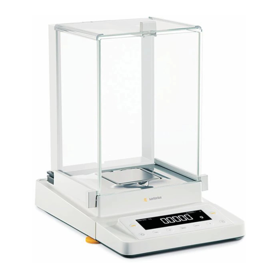
Information for the User Intended Use Cubis models are high-resolution precision and analytical balances. They were specially developed for exact determination of material mass in liquid, paste, powder or solid form. Appropriate containers must be used for each type of sample material. Balance capacity depends on the Cubis model used. -
Page 7: General View Of The Equipment
General View of the Equipment General View of the Equipment No. Description Order no. for replacement Upper sliding draft shield panel|handle Back panel 69 ME0001 Weighing pan Pan support 69 ME0002 Shield plate Pan retainer Right sliding panel|handle Leveling foot Display Display and control unit Draft shield|shield disk (only for... -
Page 8: Getting Started
Getting Started Getting Started Unpacking the Equipment Open the box. Use both hands to lift the balance, with the packaging, out of the cardboard box. Place the packaging with the balance on the floor. Remove the top part of the packaging. Operating Instructions Cubis MSE... - Page 9 Getting Started Balance with a Draft Shield Remove the packages (containing draft shield panels, weighing pan, pan sup- port, AC adapter, etc.) from the lower packaging and place them to one side. Use both hands to lift the balance out of the packaging. Exercise caution to avoid glass breakage.
-
Page 10: Equipment Supplied
Getting Started Equipment Supplied After unpacking the device and all parts, check them immediately for any visible damage as a result of rough handling during shipment. If you detect any damage, proceed as directed in the chapter entitled “Care and Maintenance" under “Safety Inspection."... -
Page 11: Assembly
Getting Started Assembly Installing the Analytical Draft Shield, Balance Assembly Place parts on the balance as shown in the picture. 1. Shield plate 2. Pan support 3. Weighing pan Slide the upper draft shield panel into the guide rails from the rear. Slide the side draft shield panel into the guide rails from the rear. - Page 12 Getting Started Installing the Draft Shield on Milligram Balances, Balance Assembly Place parts on the balance as shown in the picture. 1. Shield plate 2. Pan support 3. Weighing pan First insert the shield plate. Make sure the pin on the pan support is facing toward the front, and slide it under the clip on the pan retainer.
- Page 13 Getting Started Slide the upper draft shield panel into the guide rails from the rear while press- ing the locking tab. Slide the side draft shield panel into the guide rails from the rear, while press- ing the locking tab. 1.
- Page 14 Getting Started Assembly for Models Without a Draft Shield Place parts on the balance as shown in the picture. 1. Pan support 2. Shield plate|draft shield 3. Weighing pan Place the pan support diagonally and press down lightly. 1. Pan support Carefully turn the pan support clockwise until the two buttons engage.
-
Page 15: Transporting The Balance
Transport Transporting the Balance Transporting the Device over Short Distances As shown in this illustration As shown in this illustration. Exercise caution to avoid glass breakage. Never lift and carry the balance by its draft shield! Storage and Shipping Conditions –... - Page 16 Getting Started Installation Instructions Select the proper setup location: – Set up device on a stable, even surface that is not exposed to vibrations (e.g., weighing stone). – Ensure the device is located in a place where excessive heat cannot build up. –...
-
Page 17: Power Connection
– If the stated supply voltage or the plug design of the power cord does not comply with your country's standard, please inform the nearest Sartorius repre- sentative or your dealer. – The power connection must be made in accordance with the regulations appli- cable in your country. -
Page 18: Warm-Up Time
Getting Started Connecting the Device to AC Power Insert the AC adapter plug into the wall outlet. y The balance is now ready to use. Warm-up Time y To return precise results, the device must warm up for at least 30 minutes after initial connection to the power supply. -
Page 19: Anti-Theft Locking Device
Getting Started Equipment Not in Use Place the equipment in standby mode when not in use for a short period of time by pressing the A key. For longer periods of non-use, the device should be disconnected from the power supply. Connecting Electronic Devices (Peripherals) Make absolutely sure that the device is unplugged from the power supply before connecting|disconnecting any peripheral device (printer, scanner, PC) to... -
Page 20: Modification Options
Getting Started Modifying the Balance Setting up the Display and Control Unit at the Place of Use The display and control unit can be removed for all models to enable the operator to customize the work space. Removing the Retainer with the Display and Control Unit Remove all items (such as weights) from the draft shield. - Page 21 Getting Started Remove the upper draft shield panel. Models with the analytical draft shield (left illustration). 1. Press the locking tab 2. Remove the panel Models with the milligram draft shield (right illustration). 1. Press the locking tab 2. Remove the panel t Keep all parts in a safe place! Turn over the scale and place on a soft surface.
- Page 22 Getting Started Reinstall the upper and side shield panel: 1. Upper draft shield panel 2. Right draft shield panel 3. Left draft shield panel Level the balance (for procedure, see page 16). Removing the Display and Control Unit for Models Without a Draft Shield Carefully remove all parts as shown in the illustration.
- Page 23 Getting Started Remove the two retaining screws. Remove the display and re-insert both screws back into their holes. Carefully pull the cable connected between the display and control unit from the retainer. Determine the required cable length. Return the balance to an upright position and place the parts on the balance. 1.
-
Page 24: Under-Balance Weighing
Getting Started Under-Balance Weighing A port for an under-balance weighing hanger is located on the bottom of the bal- ance. 1. Remove the hook for under-balance weighing from the clip on the bottom of the balance. 2. Push the cover of the under-balance weighing port to one side. 3. -
Page 25: Using The Cable Opening In The Draft Shield
Getting Started Using the Cable Opening in the Draft Shield Models with an analytical draft shield have an opening for passing a cable (for example, for a temperature sensor) through to the interior of the weighing chamber. 1. Lift the locking tab on the rear panel of the analytical draft shield. 2. -
Page 26: Removing The Side Draft Shield Panels For Milligram Balances
Getting Started Removing the Side Draft Shield Panels for Milligram Balances The side draft shield panels on milligram balances can be removed and stored at the back of the analytical draft shield. This can be useful, for example, when perform- ing continuous weighing or filling operations. -
Page 27: Operation
Getting Started Operation Overview of Display and Operating Elements Position Designation Weight units Calculated-value indicator: not a weight value Taring Symbol: “Ionizer active" Symbol: “Printing mode active” Symbol: “GLP printing mode active" Symbol: “Application program active” Data output: Press this key to send readout values to the built-in data interface. -
Page 28: Basic Weighing Function
Using the Balance Basic Weighing Function Features – Taring the balance – Printing weights Using Verified Balances as Legal Measuring Instruments in the EU*: The type-approval certificate for verification applies only to non-automatic weighing instruments. For automatic operation with or without auxiliary measuring devices, you must comply with the regulations applicable to the place of installation. -
Page 29: Leveling The Balance With The Inclination Sensor
Using the Balance Level the balance with the inclination sensor It is essential for exact weighing results that the balance is absolutely level. The front leveling feet can be used to level out small tilts of the floor. An integrated sensor detects the alignment of the balance and triggers a warning message when leveling is required. -
Page 30: Calibration And Adjustment
The sensitivity of the balance can be corrected by a max. of 2%. – The balance can be adjusted using the Sartorius density determination kit YDK… If these conditions are not met, an error message is displayed (Err 02). You can use any of the following weight units in calibration|adjustment: Cal.Unit - Grams, Kilogr (not for verified models) - Page 31 Using the Balance isoCAL*: Automatisch kalibrieren und justieren In the operating menu, select isoCAL-on. The balance will automatically display a flashing “isoCAL" character whenever the ambient temperature has changed since the last calibration|adjustment or a time interval has been exceeded. The balance wants to perform an automatic adjustment.
-
Page 32: Configuration (Menu)
Using the Balance Internal Calibration|Adjustment Configuration: SETUP - Bal.Scal. - Cal.|Adj. - Cal.Int. The built-in motorized calibration weight is applied and removed automatically for internal calibration. § Select Calibration|Adjustment: Press (CAL) > The built-in weight is applied automatically > The balance is calibrated >... - Page 33 Using the Balance External Calibration Configuration: SETUP - Bal.Scal. - Cal.|Adj. - Cal.Ext. The required calibration weight is configured at the factory (see “Specifications”) Step Key (or instruction) Display|Printout 1. Tare the balance 0.0 g 2. Starts the calibration Cal.Ext. Once you store the zero point, the required calibration weight is prompted (flashing display).
-
Page 34: Functions Of The Keys During Configuration
Using the Balance Configuration (Operating Menu) You can configure the balance; i.e., adapt it to individual requirements. Functions of the Keys During Configuration: Display symbol Function Scroll through menu items Next item on current menu level (use right cursor to scroll through up to 4 menu levels) ↵... -
Page 35: Menu: Structure
Informationen für den Anwender Using the Balance Parameter Settings: Menu Level 1 Level 2 Level 3 Inform. on menu level 1) Setup Bal.Scal. Ambientconditions 1. 1. 1. Balance parameters App.Filt. Application filter 1. 1. 2. Stab.Rng.Stability range 1. 1. 3. 1. -
Page 36: Parameter Settings: Overview
Using the Balance Parameter settings: Overview ο = Factory setting; √ = User-defined setting Level 1 Level 2 Level 3 Level 4 Inform. on menu level 1) Setup Bal.Scal. Ambientconditions V.Stable Very stable 1. 1. 1. 1 Balance Adapt filter ο... - Page 37 Using the Balance Level 1 Level 2 Level 3 Level 4 Inform. on menu level 2) device 2. 1. 1. 1 extras menu Can Edit (Additional Rd.Only Read only 2. 1. 1. 2 functions) Signal Acoustic 2. 1. 2. 1 signal (beep) ο...
- Page 38 Using the Balance Indicates Level 1 Level 2 Level 3 Level 4 menu level 2) device ο Odd 2. 2. 3. 3 2. 3. 3. 3 peripher Parity Parity 2. 2. 3. 4 2. 3. 3. 4 pc-usb Even 2. 2. 3. 5 2.
- Page 39 Using the Balance Indicates Level 1 Level 2 Level 3 Level 4 menu level 4. 1. Applic. Weigh Appli- ο all 4. 2. 2. 1 Wt.Unit Disp.Dig. cation Toggle wt. unit Display accuracy LP.on.off (Last stability after load change) 4. 2. 2. 2 programs Div.
- Page 40 Using the Balance Input: ID., Date and Time Indicates Level 1 Level 2 Level 3 menu level Input Input ID., max. 7 characters 5. 1. Input Possible characters: 0 to 9; A to Z; dash|hyphen; space Set date 5. 2. DATe Time Set time...
- Page 41 Using the Balance Example: Set ID., date and time Step Key (or Instruction) Display 1. Open the menu: S hold Applic. first menu item is shown 2. Select Setup menu Input ID no. 2 + V 3. Select input for ID 4.
-
Page 42: Application Programs
Using the Balance Device Information Indicates Level 1 Level 2 Level 3 menu level Show software version 6. 1. InFo Version rel.32.05 rmation Show serial number 6. 2. Ser. no. 10801234 (To toggle focus between upper and lower display sections, press S) Show model designation 6. -
Page 43: Counting
Using the Balance Counting Display symbol: Z Purpose With the counting application, you can determine the number of parts which each have approximately equal weight. To do this, a known number of parts (the reference sample quantity) is weighed first, and the individual piece weight (reference weight) is calculated from this result. - Page 44 Using the Balance Example: Counting parts of equal weight Parameter settings: Applic. - Count. Step Key (or Instruction) Display|Printout 1. Place empty container on the balance 22.6 g 2. Tare the balance 0.0 g 3. Add reference sample quantity to container (in this example: 20 pcs) 4.
-
Page 45: Weighing In Percent
Using the Balance Weighing in Percent Display symbol: % Purpose This application program allows you to obtain weight readouts in percent which are in proportion to a reference weight. Changing the Reference Percentage Activate function: Press the S key Select the desired reference sample quantity (1 to 100): In increments of 1: Press the S key briefly In increments of 10: Press and hold the S key. - Page 46 Using the Balance Example: Determining residual weight in percent Parameter settings: Applic. - Percent Reference percentage: Ref 100% Step Key (or Instruction) Display|Printout 1. Tare the balance 0.0 g 2. Information: Enter reference percentage ref 100 (Changing the reference: see the previous page) 3.
-
Page 47: Calculation
Using the Balance Calculation Display symbol: Purpose With this application program you can calculate weight values using a multiplier or divisor. This can be used, for example, to determine the weight per unit area, or “gsm” weight (grams per square meter), of paper Setting the Factor or Divisor Activate function: Press the S key... - Page 48 Using the Balance Example: Calculating the weight per unit area of paper: An A4 sheet of paper is used in this example, with surface dimensions of 0.210 m + 0.297 m = 0.06237 m . To determine the weight per unit area, the total weight is divided by the surface. Parameter settings: Applic.
-
Page 49: Averaging (Animal Weighing)
Using the Balance Averaging (Animal Weighing) Display symbol: V Purpose Use this program to determine the weights of unstable samples (e.g., live animals) or to determine weights under very unstable ambient conditions. With this program, the balance calculates the weight as the average of a defined number of individual weighing operations (also referred to as “subweighing opera- tions”). - Page 50 Using the Balance Example: Determining animal weight with automatic start and 20 subweighing operations (measurements) Parameter settings: Applic. - AnimalW. Step Key (or Instruction) Display|Printout Place animal weighing bowl on the balance 22.6 g Tare the balance 0.0 g Change the number of subweighing operations Set number of measurements: Repeatedly press S In increments of (1, 2, 3, ..., 100)
-
Page 51: Net-Total Formulation
Using the Balance Net-total Formulation Display symbol: + Purpose With this application program you can weigh in different components up to a defined total. You can print out both the total weight and the individual weights of the components. Features –... - Page 52 Using the Balance Example: Counting parts into a container Parameter settings: Applic. - Net-Totl. Step Key (or Instruction) Display|Printout Place empty container on the balance. 65.0 g Tare 0.0 g Add first component 120.5 g Store component data 0.0 g Net Comp 1+ 120.5 g Add next component...
-
Page 53: Totalizing
Using the Balance Totalizing Display symbol: + Purpose With this application program you can add values from successive, mutually independent weight values to a total that exceeds the capacity of the balance. Features – Totalizing memory for up to 99 values –... - Page 54 Using the Balance Example: Totalizing weight values Parameter settings: Applic. - total : comp.prt: on Step Key (or Instruction) Display|Printout Tare 0.0 g Place sample on the balance (in this example: 380 g) 380.0 g Store value in memory 380.0 g Comp 1+ 380.0 g Remove sample...
-
Page 55: Mass Unit Conversion
Using the Balance Mass Unit Conversion Purpose With this application program you can change the weight value displayed from the basic weight unit to any of 4 application weight units (see table on next page). Features – Set the basic unit and display accuracy in the Setup menu: see the chapter entitled “Configuration”. –... - Page 56 Using the Balance The following weight units are available in your balance (in legal metrology, only units permitted by national law are available): Menu Item Unit Conversion Factor Display Symbol 1) UserDef. Grams 1.00000000000 2) Grams (Factory setting) Grams 1.00000000000 3) Kilogr.
-
Page 57: Density Determination
Density determination Density Determination Display symbol: u Purpose This application program lets you determine the density of solid substances using the buoyancy method. Features To enter the density of the buoyancy liquid (g|cm ) at the corresponding tempera- ture, press S. See the next page for a table of density values for water. The fac- tory setting is 1 g|cm The following formula is applied: Density of sample =... - Page 58 Density determination Printout for Density Determination RhoFl 0.99823 o : Density of liquid (g|cm 20.0 g : Weight in air 15.0 g : Weight in liquid RhoFl 4.0 o : Result: density of the sample Table: Density of H O at Temperature T (in °C) T|°C 0.99973 0.99972...
- Page 59 Density determination Parameter settings: Applic. - density - dec.plcs -1 Dec.Pl. Example: Determining the density of a solid using water as the buoyancy liquid. The density of water at 20°C is 0.99823 g|cm Step Key (or Instruction) Display|Printout 1. Attach sample holder to suspension wire 2.
-
Page 60: Iso|Glp-Compliant Printout|Record
DISO|GLP-compliant Printout|Record ISO|GLP-compliant Printout|Record Features ! No ISO|GLP-compliant record is output if any of the fol- You can have device information, ID texts and date and lowing settings are configured: time printed before (GLP header) and after (GLP footer) Prnt - Prnt.para. - Format - 16 chars the values of a weighing series. - Page 61 ISO|GLP-compliant Printout|Record The ISO|GLP-compliant printout can contain the following lines: -------------------- Dotted line 17-Aug-2008 10:15 Date|time (beginning of measurement) SARTORIUS Balance manufacturer Mod. MSE8201S Model Ser. no. 10105355 Balance serial number Ver. no. 00-39-02 Software version 2690 923 -------------------- Dotted line L ID Measurement series no.
-
Page 62: Interfaces
PCs. Merkmale of the Interfaces: – USB interface for a PC connection (PC) – 25-pin connector for Sartorius accessories (peripherals) USB Port (PC) Intended Use Any PC equipped with a USB port can be connected to a Cubis balance. - Page 63 Interfaces Initial Connection Driver software installation for the USB interface: 1. Start the installation wizard for the driver software downloaded from the Inter- net. 2. The installation procedure for the driver differs slightly depending on your Windows® version. However, the installation wizard guides you through the driver selection for all versions.
- Page 64 (www.sartorius.com “Download Center”). The many and versatile properties of these balances can be fully utilized for print- ing out records of the results when you connect your balance to a Sartorius data printer. The recording capability for printouts makes it easy for you to work in compliance with ISO|GLP.
-
Page 65: Troubleshooting Guide
The weight readout is obviously wrong The balance was not Calibrate|adjust the balance calibrated|adjusted Tare Balance not tared before weighing If any other errors occur, contact your local Sartorius Service Center. Contact information: Please point your Internet browser to: http:||www.sartorius.com Operating Instructions Cubis MSE... -
Page 66: Care And Maintenance
Care and Maintenance Service Regular servicing by a Sartorius technician will extend the service life of your balance and ensure its continued weighing accuracy. Sartorius offers its customers service contracts with regular maintenance intervals ranging from 1 month to 2 years. - Page 67 Care and Maintenance Carefully remove any sample residue|spilled powder using a brush or hand-held vacuum. If necessary, remove the weighing pan, shield plate and pan support. 1. Weighing pan 2. Shield plate|draft shield 3. Pan support Clean parts with a cloth or brush. Then reinstall them to the balance.
- Page 68 Maintenance and repair work may only be carried out by service technicians who have access to the required maintenance manuals and have attended appropriate service training courses. We recommend that the device be inspected by a qualified Sartorius service techni- cian in regard to the following: –...
-
Page 69: Transporting The Balance
Transporting the Balance If repairs are required, use the original packaging to transport the balance. To ensure adequate protection for safe shipment, Sartorius products have been pack- aged to the extent necessary using environmentally friendly materials. Only the original packaging provides optimum protection for the equipment! Disconnect the device from the power supply. - Page 70 Transport Transporting the Parts (Large Analytical Draft Shield) Get the box ready for the individual parts of the balance. Get the foam and cardboard inserts ready. Place the flat foam pieces in the box. Place the other foam pieces in the box. Operating Instructions Cubis MSE...
- Page 71 Transport Place the panels in the packaging. 1. Place the upper draft shield panel into the packaging (handle upwards). 2. Place the side panel into the packaging (handle upwards) 3. Place the other side panel into the packaging (handle downwards). Insert the front foam pieces into the box, wedging the panels into the back foam pieces.
- Page 72 Transport Place the shield plate|draft shield into the opening. Close the box. Transporting the Parts (Small Analytical Draft Shield) Get the box ready for the individual parts of the balance. Get the foam pieces ready. Place the balance parts on top of each other 1.
- Page 73 Transport Slide the parts into the foam. Place the panels in the packaging. 1. Place the side panel into the packaging (handle downwards) 2. Place the other side panel into the packaging (handle downwards) Place the foam piece in front of the parts. Place the package into the box.
- Page 74 Transport Slide the shield plate into the packaging. Close the box. Place the box into the packaging. Place the top part on to the packaging. Insert the balance into the box with cushioning. Send the packaged balance. Operating Instructions Cubis MSE...
-
Page 75: Disposal
EU legislation in Member States requires elec- trical and electronic equipment to be collected separately from unsorted municipal waste so that it may be recycled. In Germany and several other countries, Sartorius AG itself assumes responsibility for the return and conformant disposal of its elec- tronic and electrical products. -
Page 76: Specifications
Two-sided plug with a 3-pin country-specific power plug and 3-pin socket (IEC|EN60320-1|C14) for connection to the power supply Other data See label on the power supply Balance Power supply Only via Sartorius power supply 6971987 Input voltage 15 Vdc, ± 5% Power consumption 7 W (max.) Ambient conditions... - Page 77 Specifications Model-specific Data Semi-microbalances 0.01 Model MSE225S MSE225P MSE125P Readability 0.01 0.01|0.02|0.05 0.01|0.1 Weighing capacity 60|120|220 60|120 Tare range (subtractive) – 220 – 220 – 120 <±mg Repeatability 0...60g: 0.015 0...60g: 0.015 0...60g: 0.015 60...220g: 0.025 60..0.220g: 0.04 60..0.120g: 0.06 <±mg Linearity 0.15...
- Page 78 Specifications Model-specific Data Precision balances Models MSE3203P MSE2203S MSE2203P MSE1203S Readability 1|10 1|10 Weighing capacity 1,010|3,200 2,200 1,010|2,200 1,200 Tare range (subtractive) – 3,200 – 2,200 – 2,200 – 1,200 <±mg Repeatability Linearity <±mg Corner load (test load [g]) 2 (1,000) 2 (1,000) 3 (1,000) 2 (500)
- Page 79 Specifications Model-specific Data Precision balances Models MSE10202S MSE8202S MSE6202S MSE6202P MSE4202S Readability 10|20|50 Weighing capacity 10,200 8,200 6,200 1,500|3,000| 4,200 6,200 Tare range (subtractive) – 10,200 – 8,200 – 6,200 – 6,200 – 4,200 <±mg Repeatability 7|20|40 <±mg Linearity Corner load (test load [g]) 20 (5,000) 20 (5,000) 20 (2,000)
- Page 80 Specifications Model-specific Data Verified models with EC Type Approval: Semimicrobalances 0.01 mg Model MSE225S-0CE MSE225P-0CE MSE125P-0CE Type, approval number MSX, D09-09-015 Accuracy class* Scale interval d* 0.01 0.01|0.02|0.05 0.01|0.1 Weighing capacity max* 60|120|220 60|120 Calibration value e* Min. load min* Tare range (subtractive) <...
- Page 81 Specifications Model-specific Data Verified models with EC Type Approval: Precision Balances Models MSE3203P-0CE MSE2203S-0CE MSE2203P-0CE MSE1203S-0CE Type, approval number MSX, D09-09-015 Accuracy class* Scale interval d* 1|10 1|10 Weighing capacity max* 1,010|3,200 2,200 1,010|2,200 1,200 Calibration value e* Min. load min* <...
- Page 82 Specifications Verified models with EC Type Approval: Precision Balances Models MSE10202S- MSE8202S- MSE6202S- MSE6202P- MSE4202S- Type, approval number MSX, D09-09-015 Accuracy class* Scale interval d* 0.01 0.01 0.01 0.01|0.02|0.05 0.01 Weighing capacity max* 10,200 8,200 6,200 1,500|3,000| 4,200 6,200 Calibration value e* Min.
-
Page 83: Dimensions (Scale Drawings)
Dimensions Dimensions (Scale Drawings) Semimicro and analytical balances with manual DU draft shield All dimensions are given in millimeters Operating Instructions Cubis MSE... - Page 84 Dimensions Precision balances with a readability of 1 mg and manual DE draft shield All dimensions are given in millimeters Operating Instructions Cubis MSE...
- Page 85 Dimensions Semimicro and analytical balances with manual DU draft shield All dimensions are given in millimeters Operating Instructions Cubis MSE...
-
Page 86: Accessories (Options)
YSC02 Sartorius OPC server for connecting all Sartorius Cubis balances Requires 32-bit Microsoft Windows 2000 or XP with the current service packs. (Free download of a 30-day test version from the Sartorius website) – Initial license 6289OPC – Each additional license within an order... -
Page 87: Declaration Of Conformity
For informa- tion on verification and legal regulations currently applicable in your country, and to obtain the names of the persons to contact, please contact your local Sartorius office, dealer or service center. - Page 88 Declaration of Conformity Operating Instructions Cubis MSE...
- Page 89 Declaration of Conformity Operating Instructions Cubis MSE...
-
Page 90: Ec Type-Approval Certificate
Declaration of Conformity Operating Instructions Cubis MSE... -
Page 91: Plates And Markings
Plates and Markings Operating Instructions Cubis MSE... - Page 92 IPlates and Markings Operating Instructions Cubis MSE...
- Page 93 Plates and Markings Operating Instructions Cubis MSE...
- Page 94 All rights reserved. The status of the information, specifications and illustrations in this manual is indicated by the date given below. Sartorius AG reserves the right to make changes to the technology, features, specifications and design of the equipment without notice.
Need help?
Do you have a question about the Cubis Series and is the answer not in the manual?
Questions and answers