
Related Manuals for Sartorius Combics CAW3P


Summary of Contents for Sartorius Combics CAW3P
- Page 1 Operating Instructions Sartorius Combics Series Complete Scales Models C AW3P | CAW3S | CAH3 98648-018-49...
-
Page 2: Table Of Contents
Cleaning Interface Pin Assignment Chart COM2 Safety Inspection Connecting a PC via Interface COM2 Disposal Specifications Interface Pin Assignment Chart PS2 Scale Configuration Balance Dimensions Service Mode Accessories Documents List Entering Adjustment and Linearization Weights Sartorius Services Function Allocation of the Allocation for the J Key for Calibration/Adjustment Declaration of Conformity External Adjustment EC Type-approval certifi cate Internal Calibration Test Certifi cate Adjustment Without Weights Plates and Markings Appendix: Guide to Verification Function Allocation of the J Key for Linearization of Weighing Instruments and Setting/Deleting the Preload... -
Page 3: Notes On Using This Manual
Notes on Using this Manual Notes on Using this Manual t P lease read this entire manual carefully and completely before using the device. t Read the safety precautions carefully. t T his manual is part of the product. Keep it in a safe and easily accessible location. t I f the manual should be lost or misplaced, please contact Sartorius for a replacement or download the latest manual from our website: www.sartorius-mechatronics.com Symbols and Signs The following symbols are used in this manual: Warning symbol for various types of dangers. These symbols are explained in more detail in Section “Safety Instructions.“ This symbol indicates useful information and tips. This symbol indicates notes on use in legal metrology within the scope of validity of Council Directive No. 90/384/EEC, replaced by 2009/23/EC (models MS...-.CE...). e, 1 , This and similar symbols mean that the respective key should be pressed. T T ... -
Page 4: Warnings And Safety Precautions
Warnings and Safety Precautions Warnings and Safety Precautions Combics indicators comply with the European Council Directives as well as international regulations and standards for electrical equipment, electromagnetic compatibility, and the stipulated safety requirements. Improper use or handling can, however, result in damage and/or injury. t R ead these operating instructions carefully before use. This will prevent damage to the equipment. The protective conductor must not be disconnected for any reason. Use only standard cables that have protective grounding conductors. If there is visible damage to the equipment or power cord: unplug the equipment and secure it against further use. Make absolutely sure to unplug the indicator from power before you connect or disconnect any electronic peripheral devices to or from the interface port. The device should only be opened by personnel trained in accordance with Sartorius guidelines. If you use electrical equipment in installations and under ambient conditions requiring higher safety standards, you must comply with the provisions as specifi ed in the applicable regulations for installation in your country. The operator shall be responsible for any modifi cations to the equipment and for any connections of cables or equipment not supplied by Sartorius and must check and, if necessary, correct these modifi cations and connections. Information on operational quality is available upon request from Sartorius (in line with norms pertaining to immunity). Do not expose the equipment to aggressive chemical vapors or to unnecessarily extreme temperatures, moisture, shocks, or vibration. Only clean the device as stipulated in the cleaning instructions: Refer to the “Care and Maintenance“ chapter. The display value can be affected by extreme electromagnetic infl uences. Once the disturbance has ceased, the instrument can be used again in accordance with its intended purpose. Danger of Explosion! Do not use this equipment in hazardous areas. - Page 5 Sartorius products. Be sure to check the pin assignments against the chart in this manual before connecting the cable, and disconnect any lines identifi ed differently from those specifi ed by Sartorius. Connect only Sartorius accessories and options, as these are optimally designed for use with your device. Therefore, do not use any proprietary solutions. The operator shall be solely responsible for installation and testing of any modifi cations to Sartorius equipment, including connection of cables or equipment not supplied by Sartorius. Information on operational quality (in line with norms pertaining to immunity) is available on request. t I f you have any problems with your device, contact your local Sartorius offi ce, dealer or service center. IP Protection Rating IP Rating – A ll models are rated to IP44 (with option L1: IP65) – CAWxS models are rated to IP67. – CAH1E* models: platform IP65, indicator IP69K. – CAH1G* models: platform IP67, indicator IP69K. – CAWxS models are rated to IP69K with the “I69“ option. – C omplete scales with secured protective caps must be installed and tested by a certifi ed technician.
-
Page 6: Device Description
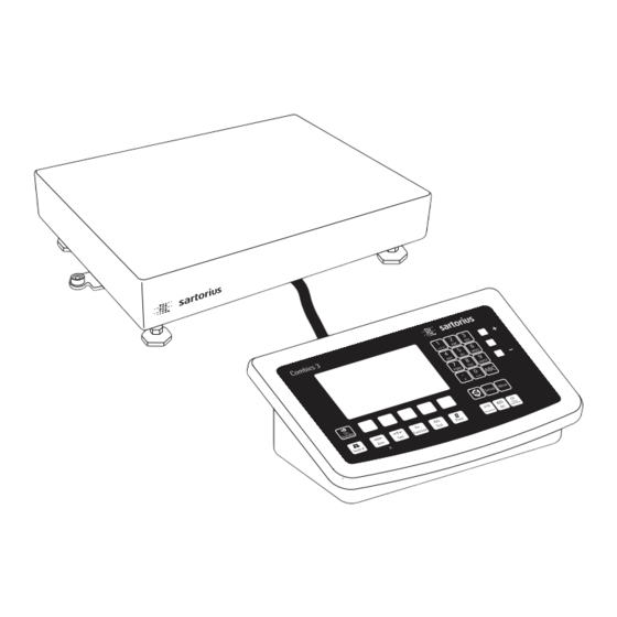
Device Description Device Description Combics complete scales: – Are robust and durable, thanks to their stainless steel housing – Are easy to clean and disinfect – Are easy to operate, thanks to the following features: – Large, backlit, fully graphical dot-matrix display – Large keys with positive click action – Can be operated independently of the weighing platform location – Have a range of interfaces for fl exible use – Have optional password protection for operating parameters Combics 3 speeds up your routine procedures with: – Integrated programs for applications (some can be combined): – Counting – Neutral Measurement – Averaging (animal weighing) – Weighing in percent – Checkweighing – Classifi cation – Totalizing – Net-total Formulation – Automatic initialization when the scale is switched on – Fast response times – Automatic taring when a load is placed on the weighing platform... -
Page 7: Overview Of Equipment
5 LEDs (for checkweighing and classifi cation) 6 Display (for details, see “Operating Design“ chapter) 7 Additional function keys (see “Operating Design“) 8 G eneral function keys: Zero, Tare, Switch function, Adjustment/ Calibration, Print/Data output (see “Operating Design“) 9 T oggle between weighing platforms (WP) 10 On/Off Rear view of indicator: CAW3P 11 “UNICOM“ Optional: – RS-232|RS-485 or 422 interface, e.g. for: – PC connection – Printer connection – Digital I/O P S 2 – 4 to 20 mA – Profi... -
Page 8: Installation
Installation Installation When a Combics indicator is ordered with special equipment, the desired options come pre-loaded from the factory. Storage and Shipping Conditions Once the equipment has been removed from the packaging, it may lose accuracy if subjected to strong vibration. If the load plate is lifted using a vacuum lifting pad, gloves, safety shoes and safety gear must be worn. Risk of injury! This work may only be carried out by reliable and authorized personnel. Suspension points are provided for weighing platforms with an overall size of 1 + 1 m or larger. Do not step under the load during weighing platform/load plate transport or when lifting. Corresponding accident prevention regulations must be followed. Do not damage the clamp boxes and load receptors during transport. – D o not expose the equipment to unnecessarily extreme temperatures, moisture, shocks, blows or vibration. – Permissible storage temperature: –10°C to +40°C Installation Location Avoid adverse infl uences at the place of installation: – Extreme temperatures (operating temperature: –10°C to +40°C) – Aggressive chemical vapors – Extreme moisture (according to IP protection class) Unpacking For devices with a platform size of 60 x 80 cm or larger: t Protective gear must be worn (safety shoes and if required, gloves) t A lways lift on the side walls when lifting or transporting the weighing platform. - Page 9 Installation CAH3 models: Remove transport locks t P lace the weighing platform at its installation location, remove the weighing pan. t Remove the transport lock: Remove screw 1 t Loosen screw 2. t Turn the mounting bracket 180° and re-secure screw 2. t Re-attach screw 1 to the lever The transport lock must be re-installed before transporting the weighing platform. Leveling the Weighing Platform The weighing platform must be exactly level to ensure reproducible weighing results every time. Therefore, the weighing platform must always be re-leveled after it has been moved to a different location. t Remove the weighing pan. t Loosen the lock nuts using a wrench (SW17). t U se a SW5 Allen key to screw the leveling feet in/out. Turning the leveling feet clockwise lifts the weighing platform, turning the leveling feet counterclockwise lowers the weighing platform. Operating Instructions Combics Complete Scales...
-
Page 10: Operating Limits
Installation t A lign the weighing platform leveling feet so that air bubble is centered within the circle of the level indicator. t C heck to ensure that all four leveling feet rest securely on the work surface. y E ach of the leveling feet must support an equal load. t R e-fasten the lock nuts after leveling: Small platforms (1 measuring cell) counter to the platform frame, large platforms (4 measuring cells) counter to the platform foot. t Place the weighing pan on the scale. Operating Limits You should not exceed the highest load for weighing platforms. The highest capacity for the weighing platform is as follows depending on the load used (center, side, one-sided corner load): Platform size Center Side Corner 320 + 240 400 + 300 130 500 + 400 300 200 500 + 400 P* 600 400 650 + 500 S** 450... - Page 11 Installation Shock Resistance The weighing platform has a robust design; however, falling weighing samples, side impacts and shocks should be avoided. The weighing platform can withstand loads specifi ed in the DIN standard IEC68 Part 2-27. Notes on Planning Superstructures Superstructures must be completely attached before the weighing platform is connected to the power. The weighing platform is designed for system integration. Scale drawings are the basis for the selection of the required superstructures. The fi xing of model CAH*IG* weighing platforms should be carried out using the YAS04IS fastening kit. Moving or rotating parts on the weighing pan must be designed so that the weighing results are not infl uenced. Rotating parts should be counterbalanced, for example. The weighing pan must be free on all sides so that there is no connection between the weighing platform and fi xed parts due to falling parts or dirt. Cables and hoses between the weighing platform and other devices may not exert any forces on the weighing platform. These cables may not touch the weighing pan. When setting up systems in hazardous areas (Zone 2 or 22), any relevant specifi cations should be observed, e. g.: EN60079-14. The design should ensure that moving parts do not cause electrostatic discharges (e.g. roller conveyors). Preload Range (Zero Set Range) The weight of the superstructures that are attached to the weighing platform is designated as a “preload.“ The preload is electronically compensated for in the weighing platform so that the full weighing range remains available and thus zeroing and/or adjustment (with external weights) is possible.
-
Page 12: Getting Started
Getting Started Getting Started Steps 1.) Set up the weighing platform with the indicator. 2.) Level the weighing platform 3.) C onnect peripheral devices, e.g. printer to the COM1 or UNICOM interface: see Data Interfaces chapter starting on page 99 4.) Connecting the device to AC power 5.) Carry out an alignment: for adjustment, see page 27, for linearization see page 24 Connecting Peripheral Devices or Another Weighing Platform An analog Sartorius platform (CAPP, CAPS) or an IS weighing platform is connected at the factory to the Combics indicator WP1 input. The load cell should be connected by a certifi ed technician who has received specialized training from Sartorius. Any installation work that does not conform to the instructions in this manual results in forfeiture of all claims under the manufacturer’s warranty. Peripheral devices should be connected by a certifi ed technician who has received specialized training from Sartorius. Any installation work that does not conform to the instructions in this manual results in forfeiture of all claims under the manufacturer’s warranty. Disconnect the equipment from the power supply before starting connection work. t Place cables from peripheral devices next to the indicator. CAW3S, CAH3 (IP69K) t Opening the Combics indicator: Loosen the ten cap nuts on the front panel. Remove the front panel. -
Page 13: Connecting An Is Weighing Platform To A Combics 3
I nsert the cable through the cable gland until the shielding (2) comes into contact with the clamps (3). Tighten the screw-down nut (4) until the gasket (5) inserted between the screw-down nut and cable forms a small beaded rim. t Check the shielding and clamps. t S ecurely connect the wires of the connecting cable in accordance with the terminal assignments. t A fter you close the housing again, use a pressure gauge to check the integrity of the IP69K protection. For details, contact the Sartorius Service Center. Connecting Cables t I nsert all cable wires through the ferrite case, wind them around the ferrite case and then reinsert back through the ferrite case. t S crew the wires tightly into the clamps. See the following pages for terminal pin allocation R efer to the data sheet or operating instructions of the weighing platform for details on the assignment of wire colors/signals. Ensure any lines that are not assigned... -
Page 14: Connecting Peripheral Devices Or A 2Nd Weighing
Getting Started Connecting Peripheral Devices or a 2nd Weighing Platform: Combics 3, Model type CAW3S | CAH3 Digital PCB PS2 COM1 COM2 COM1, COM2 and PS2 terminal assignments (applies to all PCBs) Weighing platform 1 LOAD_PRINTER 11 Clear to send (CTS) 21 5 V switched Interface 2 2 RESET_OUT 12 Data terminal ready (DTR) 22 PS/2_data... -
Page 15: Interface Pin Assignment Chart Com1
5 GND 15 GND 6 Adjustment Lock 16 GND Keys LED + Display Keypad LED + Display Interface Pin Assignment Chart COM1 Model type (IP44 protection) CAW3P COM1 female connectors: 25-pin D-Submini female connector (DB25S) with screw lock hardware for cable gland Recommended interface connector: 25-pin D-Submini (DB25) with shielded cable clamp assembly and shield plate (Amp type 826 985-1C) and fastening screws (Amp type 164868-1) COM1 pin assignments Pin 1: Shield Pin 2:... -
Page 16: Connecting A Pc Via Interface Com1
Getting Started Connecting a PC via Interface COM1 Use the following cables to connect a PC to the indicator in accordance with the RS-232C/V24 standard (max. cable length 15 m): Model type CAW3P: connecting cable 7357312 Model type CAW3S | CAH3: connecting cable YCC02-D09F6 RS232 Pin assignment Pin assignments for the cable from the indicator to an RS-232 PC interface (COM1). Indicator side PC side Model type CAW3P DSUB connector 25-pin D-Sub male connector 9-pin or 25-pin Sgn GND 5 GND 7 GND TxD 2 RxD 3 RxD RxD 3 TxD 2 TxD DTR 8 CTS... -
Page 17: Interface Pin Assignment Chart Com2
Getting Started Interface Pin Assignment Chart COM2 Model type (IP44 protection) CAW3P COM1 female connectors: 25-pin D-Submini female connector (DB25S) with screw lock hardware for cable gland Recommended interface connector: 25-pin D-Submini (DB25) with shielded cable clamp assembly and shield plate (Amp type 826 985-1C) and fastening screws (Amp type 164868-1) COM1 pin assignments Pin 1: Shield Pin 2: Data output (TxD) Pin 3: Data input (RxD) Pin 4: Pin 5: Clear to send (CTS) Pin 6: Not assigned Pin 7: Internal ground (GND) -
Page 18: Connecting A Pc Via Interface Com2
Getting Started Connecting a PC via Interface COM2 Use the following cables to connect a PC to the indicator in accordance with the RS-232C/V24 standard (max. cable length 15 m): Model type CAW3P: connecting cable 7357312 Model type CAW3S | CAH3: connecting cable YCC02-D09F6 RS232 Pin assignment Pin assignments for the cable from the indicator to an RS-232 PC interface (COM1). Indicator side PC side Model type CAW3P DSUB connector 25-pin D-Sub male connector 9-pin or 25-pin Sgn GND 5 GND 7 GND TxD 2 RxD 3 RxD RxD 3 TxD 2 TxD DTR 8 CTS... -
Page 19: Interface Pin Assignment Chart Ps2
Internal ground (GND) Pin 4: +5V switched Pin 5: Keyboard clock Pin 6: Not used Connecting a Bar Code Scanner Accessory YBR02CISL t Disconnect the indicator from AC power (unplug the AC adapter) For CAW3P models: t C onnect the barcode scanner via PS/2. For CAW3S | CAH3 models: t P in assignment, see “Connecting Peripheral Devices“ (implemented via the YCC02-BR02 connecting cable or as option M8) on page 14. NOTE: This equipment has been tested and found to comply with the limits pur- suant to part 15 of FCC Rules. These limits are designed to provide reasonable protection against harmful interference. This equipment generates, uses and can radiate radio frequency energy and, if not installed and used in accordance with these instructions, may cause harmful interference to radio communications. For information on the specific limits and class of this equipment, please refer to the... -
Page 20: Safety Precautions
Closing the Combics Indicator t Re-attach the front panel and secure it with the ten cap nuts ( 1Nm ). Connecting the Device to AC Power The indicator is powered through the pre-installed power cord. The power supply is integrated into the indicator. The device can be operated with a supply voltage of 100 V to 240 V. The power connection must be made in accordance with the regulations applicable in your country. The printed voltage rating (see type label) must match the voltage in the place of installation. If the voltage specified on the label or the plug design of the AC adapter do not match the rating or standard you use, please contact your Sartorius office or dealer. t C heck the voltage rating and plug design. t T he device must be plugged into a properly installed wall outlet. Protection Class 1 Device t T he device must be plugged into a properly installed wall outlet which has a protective grounding conductor (PE). Safety Precautions If you use an electrical outlet that does not have a protective grounding conductor, ensure that an equivalent protective conductor is installed by a certified electrician (as specified in the applicable regulations for installation in your country). -
Page 21: Scale Configuration
Configuring Weighing Platforms Configuring Weighing Platforms Service-Mode Purpose The Service mode enables access to additional menu items in the Setup menu which are not displayed when the Service mode is not active. The most important calibration and adjustment work for the indicator and for the connected weighing platform can be carried out in the Service menu, e.g. ADC configuration. When the Service mode is active, an “S” is shown in the top right-hand corner of the display. To deactivate the Service mode, restart the indicator (turn the indicator off and back on again). Activating the Service Mode t Press e to turn on the device. y W hen turned on the scale is in an application program. t E nter the service password (see Appendix General User Password) and press M to confirm. y T he device in now is Service mode. An “ “ appears in the top right-hand corner of the display. t P ress the “ “ soft key several times to select the “ Device “ line. parameters t Press the “... - Page 22 Ext. cal./adjust.; user-defi ned weight Ext. lineariz.; factory-def. wts Ext. lineariz.; user-def. wts Set preload Delete preload Key blocked Cal./adj. sequence Cal. then auto adjust o Cal. then manual adjust isoCAL function o Off Adjustment prompt Activate external adjustment o Activated Deactivated Parameter for external weight Cal./adj. weight: Lin. weight 1...4: Adjust without weights Input parameters Nominal load: Resolution: Sensitivity 1…4: Save parameters Yes o No Geographical data Input parameters Geographical latitude Altitude G ravitational acceleration Save parameters Yes o No ) Equipment version: – then blocked internally ) Not available on devices verifi ed for use in legal metrology ) Only when operated with Sartorius IS weighing platforms or an external ADC Operating Instructions Combics Complete Scales...
- Page 23 Confi guring Weighing Platforms Device Parameters Internal Calibration/Adjustment unit Grams /g Kilograms /kg Tons /t o Pounds /lb Menu items “Adapt fi lter“ - “Factory settings: only bal. func,“ see the “Setup Overview (Parameters)“ section Off COM-1 (when the WP is assigned to this interface) COM-2 (when the WP is assigned to this interface) UNICOM (only if available) WP2, see the “Setup Overview (Parameters)“ section RS-232 ) similar to “Internal“ menu for WP1 RS-485 ) similar to “Internal“ menu for WP1 o Off COM-1 similar to WP 1 COM-2 similar to WP 1 COM-1, see the “Setup Overview (Parameters)“ section COM-2, see the “Setup Overview (Parameters)“ section “Control I/O ports“ - “Terminal data,“ see the “Setup Overview (Parameters)“ section SQmin SQmin input SQmin WP1 SQmin WP1 0.000 kg SQmin WP2 SQmin WP2 0.000 kg SQmin WP3 SQmin WP3 0.000 kg Display No o Yes GMP print...
- Page 24 Confi guring Weighing Platforms Setup Menu for A/D Converter Configuration Setup access in Service mode WP1 – Internal – ADC confi guration Standard confi guration Ranges Single-range mode Scale interval d Max. cap. Multi-interval mode Scale interval d Range 1 Range 2 Range 3 Max. cap. Multiple-range Scale interval d mode Range 1 Range 2 Range 3 Max. cap. Available units User-defi nable /o Grams /g Kilograms /kg Carats /ct ... Save parameters Yes o No o Verifi...
- Page 25 Confi guring Weighing Platforms Analog/Digital Converter (ADC) Purpose Adjust the parameters of the analog/digital converter to the connected load cell or weighing platform. After ADC confi guration, the ADC in connection with the load sensor is defi ned as a scale. O nce the ADC confi guration has been locked, the indicator can no longer be used to infl uence weighing results. The scope of functions available in the weighing instrument is defi ned by the A/D converter. Weighing functions that can be activated include reading weight values, taring, adjustment, reading the tare value, saving/deleting the tare entry. Setup Information – A DC confi guration is only possible when the menu access switch is open. Re-close the menu access switch after ADC confi guration. – B efore ADC confi guration, you must fi rst set whether or not the weighing platform will be used as a standard or verifi able weighing platform. – A DC confi guration is carried out in the Service mode in the Setup menu under “WP 1“ for the fi...
- Page 26 Confi guring Weighing Platforms Select the desired confi guration using the “ “ or “ “ soft key. Confi rm your selection using the “ “ key. Make additional settings in the submenu: scale interval d/verifi cation scale interval e, minimum load (Verifi able confi guration only), range limits (Multi-interval or Multiple range mode only) and maximum capacity. Confi rm using the “ “ soft key or cancel using “ .“ Scale Interval d Scale interval d indicates the resolution of the weighing instrument. The scale interval d can be entered only in increments of 1, 2, 5, 10, 20, etc. When using verifi able or verifi ed weighing platforms, the scale interval d is the same as the verifi cation scale interval e. Verification Scale Interval e The verifi cation scale interval e indicates the resolution of the weighing instrument in legal metrology. The verifi cation scale interval e can be entered only in increments of 1, 2, 5, 10, 20, etc. For weighing instruments of accuracy class l or m, e = d. This is why the scale interval d does not need to be entered separately. When “Standard confi guration” is used, this menu item is not displayed. Minimum Capacity (Min.
- Page 27 Confi guring Weighing Platforms Analog/Digital Converter (ADC) Configuration Condition The weighing platform must already be connected. Open the Menu Access Switch The menu access switch is located on the back of the indicator right next to the weighing platform connection. t Remove the cap. t S lide the switch to the left (= “open“ position). Activating the Service Mode t See “Service Mode“ on page 17. Configuration t Select weighing platform “ .“ WP 1 t I f the “ “ setting is not already activated (marked by “ “), select Internal the setting using the “...
- Page 28 Confi guring Weighing Platforms In the example shown here, “ “ has been selected Single range mode (marked by “ “). t T o select a different weighing range confi guration, use the “ “ or “ “ soft key to select the corresponding line and open the selected menu using the “ “ soft key. y T he selected weighing range confi guration is now active. When you return from the input menu for entering the weighing range parameters, the new range confi guration is marked by a “ .“ For more information about range confi guration, please see “Setting Parameters for ADC Confi guration.“ The default values displayed depend on the data record loaded and might have to be changed. In the example shown here, the A/D confi guration is set with a “Verifi able” data record in single-range mode. Single-range Mode t Select the individual input fi elds using the “ “ or “...
- Page 29 Confi guring Weighing Platforms Multi-interval Mode The illustration shows an example of the input menu opened for multi-interval mode range confi guration. This example shows the parameters for a scale in “Verifi able” confi guration, with 2 weighing ranges and a maximum capacity of 6.000 kg. – Range 1: 0…3.000 kg with e1 = 0.001 kg – Range 2: 3.002…6.000 kg with e2 = 0.002 kg t E nter the verifi cation scale interval for Range 1 in the “ “ input fi eld. The minimum capacity for a class l scale must be set to 0.02 kg. t Use the “ “ soft key to go to the next menu level. y T he active range confi guration is marked with “ .“ t Use the “ “ soft key to go back to the “ “ menu. Verifi able Selecting Units t U se the “q“ and “O“ soft key to open the “Available units“...
- Page 30 Confi guring Weighing Platforms t T o change the calibration/adjustment unit, select the unit using the “ “ or “ “ soft key and confi rm using the “ “ soft key. t Use the “ “ soft key to go back to the “ “ menu. Internal t Use the “ “ soft key to select the “ “ menu item. ADC confi guration t U se the “ “ and “ “ soft key to select the “ Save confi guration “ menu item. data t T o save the confi guration, use the “Q“ soft key to select “ “ and confi...
- Page 31 Confi guring Weighing Platforms T he displays depicted in the next two illustrations on the left show data from a multi-interval scale confi gured as described above, or a similarly confi gured multiple-range scale. I f the A/D converter was confi gured with a “Verifi able” data record, the lines for display of metrological data (lines 1 and 2) show the data valid for use in legal metrology. The current range (e.g. ) is displayed top left under the weighing point for multiple-range scales. ADC Configuration with Load Cell(s) Connected Procedure: 1. O pen the menu access switch, see “Analog/Digital Converter (ADC) Confi guration.“ 2. Activate the Service mode, see “Service Mode.“ 3. Confi gure WP 1, see “Analog/Digital Converter (ADC) Confi guration.“ 4. S et single-range mode, for example, see “Analog/Digital Converter (ADC) Confi...
-
Page 32: Entering Adjustment And Linearization Weights
Confi guring Weighing Platforms Entering Geographical Data for Use in Legal Metrology Purpose Entering geographical data allows the external adjustment of weighing equipment at a place (e.g. at the manufacturer or vendor‘s place of business) that is not the same as the place of installation. If the weighing equipment is adjusted at the place of installation, it is not necessary to enter geographical data. The sensitivity of weighing equipment changes depending on the place of installation as it is dependent on the on-site gravitational force – or, more precisely, on gravitational acceleration. Saving geographical data makes it possible to change the place of installation of the weighing equipment after external adjustment has been carried out. The adjustment of weighing equipment is valid at the place of installation and within a specifi c tolerance zone. At 3000 e this zone extends ±100 km from the set geographical latitude and ±200 m from the set elevation above sea level. Installation Location in Germany An exception to this is the setting for “Germany (Zone D):” If during external adjustment of weighing equipment within Germany the geographical data – Geographical latitude: 51.00 degrees – 513 m elevation above sea level are entered, the weighing equipment can be used throughout Germany. Gravitational acceleration for “Germany (Zone D)” is 9.810 m/s . On delivery the geographical data for “Germany (Zone D)” are entered in the output device. It is recommended to use the geographical data settings for “Germany (Zone D)” when adjusting and delivering the weighing equipment within Germany. - Page 33 Confi guring Weighing Platforms Procedure t Remove the cap. t Slide the menu access switch to the left (= “open“ position). I f the device is part of a verifi ed weighing facility, this will only be possible if the verifi cation seal is broken. The weighing equipment must then be verifi ed again. t Activate the Service mode, see “Service Mode.“ t S elect weighing platform “ “ in the “ “ WP 1 Device Parameters menu item. t I f the “ “ setting is not already activated (marked by “ “), select Internal the setting using the “ “ or “ “ soft key and confi rm with “ .“ y The menu for the “...
- Page 34 Confi guring Weighing Platforms Entering Gravity t Use the “ “ or “ “ soft key to select the corresponding input fi eld. t Enter gravity in m/s via the keypad and confi rm using the “ “ soft key. Permissible value range: d < gravity 2 d < 9.700000 9.900000 In the example shown here, the value for gravity has been changed. The new value, m/s2 applies to the setting “Germany (Zone D).” 9.810000 t Press the “ “ soft key to exit the Input menu. t Use the “ “ soft key to select the “ “ menu item. Save parameters t Use the “ “ soft key to select “ “ and use the “ “ soft key to confi rm. y T he message “ “ appears briefl y.
- Page 35 Confi guring Weighing Platforms t Press J to start an external adjustment. y T he display “ C.EXT.D “ appears briefl y. In the example, the altitude and latitude of the installation location are being entered. C.EXT.D C.EXT.DEF. y The display “ Altitud “ appears briefl y. Altitud C.EXT.DEF. y T he altitude at the place of installation is displayed in meters above sea level - here, the altitude for “Germany (Zone D).” Press J to confi rm the displayed value or press ( to cancel the adjustment. y The display “ Latitud “ appears briefl y. Latitud C.EXT.DEF. y T he geographical latitude of the place of installation is shown in degrees north or degrees south - here the latitude setting for “Germany (Zone D).”...
- Page 36 Confi guring Weighing Platforms If gravity is being entered instead of altitude and latitude, then “Gravity“ is displayed for a brief time after “CAL.“ The entered value appears in m/s , here for the “Germany (Zone D)“ setting. t Press J to confi rm the displayed value or press ( to cancel the adjustment. y Y ou are prompted to place the required weight on the platform (e.g.: 5.0 kg). The subsequent steps for completing the calibration/adjustment are described in the chapter entitled “Operation” under “Calibration and Adjustment.“ t S lide the menu access switch to the right (= “closed“ position) and reattach the cap. y The display goes out and the device restarts. Then weighing mode is active. If adjustment is carried out using a verifi able confi guration data record, the lines for display of metrological data (lines 1 and 2) show the data valid for use in legal metrology, if the menu access switch is closed. See also the chapter “Operation“, “Confi guration for Use in Legal Metrology.“ Operating Instructions Combics Complete Scales...
- Page 37 Confi guring Weighing Platforms Entering Adjustment and Linearization Weights Purpose Entering adjustment and linearization weights. Procedure See also “Calibration and Adjustment“ in the chapter called “Operation“. t Remove the cap. t Slide the menu access switch to the left (= “open“ position). t Activate the Service mode, see “Service Mode.“ t S elect weighing platform “ “ in the “ “ WP 1 Device Parameters menu item. t I f the “ “ setting is not already activated (marked by “ “), select Internal the setting using the “ “ or “ “ soft key and confi rm with “ .“...
-
Page 38: Function Allocation Of The Allocation For The J Key For Calibration/Adjustment
Confi guring Weighing Platforms Function Allocation of the allocation for the Key for Calibration/Adjustment Purpose The J key is used for the calibration/adjustment function. Key settings can be changed when the Service mode is activated: Procedure t Remove the cap. t Slide the menu access switch to the left (= “open“ position). t Activate the Service mode, see “Service Mode.“ t S elect weighing platform “ “ in the “ “ WP 1 Device Parameters menu item. t I f the “ “ setting is not already activated (marked by “ “), select Internal the setting using the “... -
Page 39: External Adjustment
Confi guring Weighing Platforms t Use the “ “ soft key to open the “ menu. CAL key function y The “ “ submenu is displayed. CAL key function t U se the “ “ or “ “ soft key to select the corresponding menu item and confi rm with “ .“ y The menu item is marked by a circle “ .“ N ote The functions that can be confi gured in the “ “ CAL key function submenu depends on the selected weighing platform and its confi guration data. Functions that cannot be accessed are not displayed in the selection screen. I mportant Note! The function set in the “... - Page 40 Confi guring Weighing Platforms t Press e to turn off the device. t Press e turn the device back on. y T he Sartorius logo is displayed briefl y, after which the device is in normal weighing mode. t Press ( to unload and zero the scale. t Press J to start the external adjustment. y The display “C.EXT.D“ appears briefl y. Note If the display of geographical data (elevation and latitude or gravity) is activated, C.EXT.D this data is displayed and confi rmed each with a press of the J key (you can cancel the calibration / adjustment process using the ( key). See also “Entering Geographical Data for Use in Legal Metrology“ in this chapter. C.EXT.DEF. Procedure y T he target value of the required adjustment weight (5.000 kg in the example) is displayed as a negative value. t Place the required adjustment weight on the platform. Note If the calibration/adjustment sequence is set to automatic (“...
- Page 41 Vers.no. 1.02.101110 BVers. 01-63-02 -------------------- t Unload the scale. External calibration t Press e to turn off the device. Nom. 5.000 kg t Press e turn the device back on. Diff. + 0.010 kg y T he Sartorius logo is displayed briefl y, after which the device is in normal External adjustment weighing mode. Diff. + 0.000 kg -------------------- 14.01.2010 13:52 Name: -------------------- If a serious operator error should occur during calibration (for example, if the menu setting “...
- Page 42 Configuring Weighing Platforms t Press e to turn off the device. t Press e turn the device back on. y T he Sartorius logo is displayed briefly, after which the device is in normal weighing mode. t Press ( to unload and zero the scale. t Press J to start the external adjustment. y “ The display “C.EXT.U appears briefly. Note If the display of geographical data (elevation and latitude or gravity) is activated, C.EXT.U this data is displayed and confirmed each with a press of the J key (you can cancel the calibration/adjustment process using the ( key). See also “Entering Geographical Data for Use in Legal Metrology“ in this chapter. C.EXT.USE. Procedure t P ress J to confirm the displayed value or press ( to cancel the adjustment. y T he target value of the required adjustment weight (6.000 kg in the example) is displayed as a negative value. t Place the required adjustment weight on the platform. I f the calibration/adjustment sequence is set to “Cal. then auto adjust”, refer to the note under “External Calibration/Adjustment with Factory-Defined Weight...
-
Page 43: Internal Calibration
Configuring Weighing Platforms If a serious operator error should occur during calibration (for example, if the menu setting “ “ is active and the wrong calibration Cal. then auto adj. weight is placed on the scale), the scale might completely fail to stabilize, which means it cannot show a zero point. In this case, select the “ “ menu and set the Adjust without weights mean sensitivity of the strain-gauge weighing beam to 2.0 mV/V. Then re-adjust the scale. See also “Adjust without weights.“ Internal Calibration/Adjustment T his function is available only if a digital weighing platform (for example, an IS platform) is connected to WP 1, either as a second weighing platform or as the only weighing platform without using the built-in A/D converter WP 1. The connection can be made both via the COM1, COM2 or UNICOM interface with a corresponding configuration as well as via the expansion PCBs for WP 1 or WP 2. This function is also accessible without activating the Service mode. Adjustment Without Weights Purpose In the Service menu, adjustment without weights can be carried out by entering the characteristic data of the load cells. Adjustment without weights may not be carried out on weighing equipment used in legal metrology. Setup information – A djustment without weights is only possible when the menu access switch is open in the Service mode. - Page 44 Configuring Weighing Platforms Procedure t Remove the cap. t Slide the menu access switch to the left (= “open“ position). t Activate the Service mode, see “Service Mode.“ t S elect weighing platform “ “ in the “ “ WP 1 Device Parameters menu item. t I f the “ “ setting is not already activated (marked by “ “), select Internal the setting using the “ “ or “ “ soft key and confirm with “ .“ y The menu for the “ “ device parameters is displayed. WP-1 INTERNAL t U se the “ “ or “ “ soft key to select and open the “...
- Page 45 Configuring Weighing Platforms If the weighing platform has multiple load cells, multiply the nominal capacity accordingly. Example: The weighing platform has 4 load cells each at 50 kg. The nominal capacity is 4 x 50 kg = 200 kg. In the example shown here, the weighing platform consists of one load cell with a maximum capacity of 10 kg. t Press 10.00 and confirm with the “ “ soft key. y The “ “ input field is selected. Resolution T he smallest digit “d“ is entered in this field in “kg“. The value must correspond to the “ “ entry in “ ADC configuration: Standard: .“ Ranges: Single-range mode In the example, this should be d = 0.002 kg. t Press 0.002 and confirm with the “ “ soft key. y The “ “ input field is selected. Sensitivity 1 If the weighing platform has multiple load cells, enter the sensitivity either – u nder “ “ … “...
-
Page 46: Function Allocation Of The J Key For Linearization And Setting/Deleting The Preload
Configuring Weighing Platforms Function Allocation of the J Key for Linearization and Setting/ Deleting the Preload Purpose The J key is normally used for the calibration/adjustment function. The following additional functions can be allocated to the key when the Service mode is activated: – External linearization with default weights – External linearization with entered linearization weights – Internal linearization (for external IS platforms only) – Set preload – Delete preload Once linearization has been completed, or after a preload has been set or deleted the function of the J key must be reallocated back to its original function in the Setup menu, e.g. external calibration/adjustment with default weights. Procedure t Remove the cap. t Slide the menu access switch to the left (= “open“ position). t Activate the Service mode, see “Service Mode.“ t S elect weighing platform “ “ in the “... -
Page 47: External Linearization
Configuring Weighing Platforms External Linearization with the Factory-Defined Weight (Default Weights) Setup Information – T his function is accessible only if the software and the functionality of the connected weighing platform permit this operation. – E xternal linearization when weighing in legal metrology is only possible when the menu access switch is open. – T he J key must be assigned the “External linearization“ function, see “Function Allocation of the J Key for Linearization and Setting/Deleting the Preload.“ – Activating the display of geographical data has no effect on this function. Once linearization has been completed, the J key must be reallocated back to its original function in the Setup menu, e.g. external calibration/adjustment with default weights. Procedure t F or scales used in legal metrology, slide the menu access switch to the left (= “open“ position). y The display goes out and the device restarts. Then weighing mode is active. t Press ( to unload and zero the scale. - Page 48 Confi guring Weighing Platforms External Linearization with User-Defined Weights Setup Information – T his function is accessible only if the software and the functionality of the connected weighing platform permit this operation. – E xternal linearization when weighing in legal metrology is only possible when the menu access switch is open. – T he J key must be assigned the “External linearization“ function, see “Function Allocation of the J Key for Linearization and Setting/Deleting the Preload.“ – Activating the display of geographical data has no effect on this function. Once linearization has been completed, the J key must be reallocated back to its original function in the Setup menu, e.g. external calibration/adjustment with default weights. Configuration t S et the linearization weights, see “Entering Adjustment and Linearization Weights.“ Procedure t F or scales used in legal metrology, slide the menu access switch to the left (= “open“ position).
- Page 49 Configuring Weighing Platforms -------------------- t P ress J to apply linearization weight 1 or press ( to cancel the 14.01.2010 13:00 linearization function. Type CAW3P1-6DC-LCE y A fter the linearization weight 1 has been saved you will be prompted to place Ser.no. 12345678 the second linearization weight on the weighing pan. Vers.no. 1.02.101110 BVers. 01-63-02 t Repeat the procedure for all required linearization weights. -------------------- y A fter the last linearization weight has been saved you will be prompted to Linearization remove any load from the weighing pan. Wt.1 1.500 kg t Remove all linearization weights from the weighing platform. Wt.2 3.000 kg y T he zero point is applied automatically after a brief time. The indicator Wt.3 4.000 kg Wt.4...
-
Page 50: Setting The Preload
Set preload Setup Information – S etting the preload when weighing in legal metrology is only possible when the menu access switch is open. – T he J key must be assigned the “Set preload“ function, see “Function Allocation of the J Key for Linearization and Setting/Deleting the Preload.“ – Activating the display of geographical data has no effect on this function. Once the preload has been set, the J key must be reallocated back to its original function in the Setup menu, e.g. external calibration/adjustment with default weights. Procedure F or scales used in legal metrology, slide the menu access switch to the left (= “open“ position). Press e turn the device back on. T he Sartorius logo is displayed briefly, after which the device is in normal weighing mode. Press ( to unload and zero the scale. y Display after the scale has been zeroed. Place the preload weight on the weighing platform. Press J to start “Set preload.“ y The display “ SET PREL “ appears briefly. A fter a short period of time the preload will be applied and the indicator will automatically switch back to weighing mode. -
Page 51: Clearing The Preload
– T he J key must be assigned the “Delete preload“ function, see “Function Allocation of the J Key for Linearization and Setting/Deleting the Preload.“ – Activating the display of geographical data has no effect on this function. Once the preload has been deleted, the J key must be reallocated back to its original function in the Setup menu, e.g. external calibration/adjustment with default weights. Procedure t F or scales used in legal metrology, slide the menu access switch to the left (= “open“ position). t Press e turn the device back on. y T he Sartorius logo is displayed briefl y, after which the device is in normal weighing mode. t Remove the preload weight from the weighing platform. y The display shows the removed preload weight as a negative value. t Press J to start “Delete preload.“ y The display “CLR PREL“ appears briefl y. A fter a short period of time the preload will be deleted and the indicator will automatically switch back to weighing mode. After the “Delete Preload” operation has been completed, the scale is zeroed. When deleting the preload is complete, the GMP-compliant printout shown on the -------------------- 14.01.2010... -
Page 52: Operating Design
Operating Design Operating Weighing Mode Operating Design Design You can use the Combics 3 to record weight values from 1 to 3 weighing platforms, calculate and display weight values through application programs, and assign IDs to the samples weighed. Configure the indicator first, using the Setup menu for the desired application program (printer settings, etc.). Then you can begin weighing. Labeled Keys When a key is pressed that does Some keys have a second function, activated by pressing and holding the key for not have an active operating mode over 2 seconds. Whether a function is available depends on the indicator operating function, an acoustical signal state and operating menu settings. (double beep) sounds and the On/Off key message “——-—“ is displayed for 2 seconds. The display then standby is displayed in Standby mode. returns to the previous screen If a second weighing platforms is connected, this key toggles the display between content. the two readouts. – Press briefly: Zero – Press briefly: cancels calibration/adjustment – Press longer than 2 seconds: displays the adjustment/configuration counter Tare the scale: press briefly. - Page 53 Operating Design Toggles to the Info mode: Press longer than 2 seconds. Product data memory: Saves initialization and user data (product and tare values). The product data memory can store over 400 product and tare values. Opens/Exits the Setup program ... Enters numbers, letters and other characters. Toggles between numeric and alphabetic input. Soft keys The functions of active soft keys are indicated by symbols and abbreviations in the last line on the display. Abbreviation examples: – : ID list – : Delete entry DELETE Symbols used for soft key functions: oo: Return to initial state o: Next higher menu level O: S how items under selected entry Q: S croll up in the input/output window q: Scroll down in the input/output window l: Set the selected menu parameter Numeric Input via the Keypad t T o enter numbers (one digit at a time): Press 0, 1, 2 … 9...
- Page 54 Operating Design Entering Spaces via the Keypad t Press the a key. y “ABC“ is displayed. t Press the 0 key. y The corresponding selection is displayed. The fl ashing cursor marks the space. t Press the F1 soft key ( ) or wait 2 seconds. y The space appears on the display. Special Character Input via the Keypad t Press the a key. y “ABC“ is displayed. t Press the 1 key. y T he corresponding character selection is displayed. The fl ashing cursor marks the fi rst character. t Press the F1 soft key ( ) or wait 2 seconds.
- Page 55 Operating Design Saving Settings in Weighing Mode Y ou can specify the save type used in the Application Parameters Setup menu. B y default, all application parameters saved (e. g., reference values) remain in memory and are available when the device has been switched off and then on again – y ou return to the originally selected application from a second one (e. g., when – you switch from Averaging back to Counting all parameters saved for Counting are available). Applying the Tare Weight To save the weight on the weighing platform as a tare weight: t Place the tare object on the weighing platform. t Press ). y The value is applied as the tare value. Input Through the Digital Control Port Y ou can connect a remote hand switch or foot switch to the input control line, for use with all application programs. The following functions can be assigned in the Setup menu Device Parameters:Control I/O...
- Page 56 Operating Design Display in Weighing Mode Lines for metrological data Bar graph Weighing Mode: Display of Measured and Calculated Values Info/Status line The display is divided into several sections. Line for measured values Text lines Soft key labels Plus or minus sign Application symbol Stability Tare memory Calculated values Unit Battery symbol...
- Page 57 Operating Design Data in Tare Memory, Calculated Value, Identification of the Active Weighing Platform when More Than One Platform is Used Identification of calculated values (values not used in legal metrology) Indicates gross value or net value (data in tare memory) B/G NET Indicates manual tare input (using a barcode scanner) when viewing tare information. Display of the active weighing platform when 2 platforms are connected. The display flashes for a ISO Cal adjustment prompt if WP 1 is an IS-weighing platform. When the timer is active ( Setup:Device Parameters: ), the symbol flashes to indicate Operating Parameters:Timer that the set time has halfway expired. Application, Printing and Battery Symbols Printing in progress GMP-compliant printout active Battery status: ‘Battery fully charged’ or ‘Battery empty’...
-
Page 58: Menu Operating Design
Operating Design LEDs LEDs indicate – whether the weight exceeds tolerance limits for checkweighing – the weight value classification for the Classification application Error Codes – I f a key is inactive, “ ” and/or “ ”” is displayed ------- No function (2 sec.) and an acoustic signal (double- beep) is emitted – T emporary errors are displayed for 2 seconds in the measured value/result line via an error code (e .g., ); fatal errors (e .g., ) are INF 09 ERR 101 displayed continuously until cleared via a restart. Error codes are described in detail in “Data Interfaces“ in “Error Codes.“ Menu Operating Design Operating Example: Setup:Device parameters: WP 1:Internal:Adapt filter o Marks the current menu setting Configuring parameters: t Soft key “... -
Page 59: Confi Guration
Operating Design Configuration You can confi gure the indicator by selecting parameters in the Setup menu. These are divided into the following groups (menu level 1), menu structure see section the “Setup Overview (Parameters)“ section – Application parameters – Fn key function – Device parameters – (device-specifi c information) Info – Language When used in legal metrology, not all parameters can be accessed. The indicator only displays parameters that can be selected. Factory-set parameters are identifi ed by an “o” in the list starting on the next page. Setting the Language You can choose from the following languages for displaying information: – Deutsch – (factory setting) English – U.S. mode – Français –... -
Page 60: Setting Up Password Protection
Operating Design t Press the soft key to save the setting. y The setting selection “ “ moves to “ .“ U.S. mode t Press M or to exit the Setup menu. Setting up Password Protection t Press e to turn on the device. t Press M. y The menu appears on the display. t P ress the “ “ soft key several times to select the “ Device “ line. parameters t Press the “ “ soft key. t Press the “ “ soft key several times to select the “ “ line. Password y The input line appears on the display. - Page 61 Operating Design Setting up Password Protection t Press e to turn on the device. t Press M. y The menu appears on the display. t P ress the “ “ soft key several times to select the “ Device “ line. parameters t Press the “ “ soft key. y The Access window appears on the display. t E nter the password via the keypad, see “Numeric Input via the Keypad“ and “Letter Input via the Keypad.“ t Press the “ “ soft key. y The device selection appears on the display. t Press the “ “ soft key several times to select the “ “ line. Password y The input line appears on the display. t Press c several times to delete the password.
- Page 62 Operating Design Printing Parameter Settings Example: Maximum 20 characters per line. -------------------- 12.01.2010 09:46 Type CAIS3 Ser.no 12345678 Vers. 1.02.101110 BVers. 01-63-02 -------------------- SETUP DEVICE -------------------- WP 1 Internal WP 2 off COM1 Data communcations Baud rate 1200 Baud Parity Number of Stop bits 1 Stop bit Handshake mode Hardware 1-char Number of data bits...
-
Page 63: Setup Overview (Parameters)
Ext. cal./adj.; user-defined wt. Key blocked Cal./adj. sequence Cal. then auto adjust o Cal. then manual adjust isoCAL function o Off Adjustment prompt Activate external adjustment o Activated Deactivated Parameter for external weight Cal./adj. weight: Calibration/adjustment unit Grams /g Kilograms /kg Tons /t Pounds /lb Adapt filter Min. vibration o Normal vibration Strong vibration Extreme vibration Application filter o Final readout Filling mode Low filtering Without filtering Stability range 1/4 digit 1/2 digit 1 digit o 2 digits 4 digits 8 digits ) Equipment version: – then blocked internally ) Not available on devices verified for use in legal metrology ) Only when operated with Sartorius IS weighing platforms or an external ADC Operating Instructions Combics Complete Scales... - Page 64 Operating Design Device Parameters WP 1 Internal Stability delay Without delay o Short delay Average delay Long delay Taring Without stability o After stability Autozero o On Off Weight unit 1 User-definable / o (factory setting: grams) Grams /g o Kilograms / kg Carats / ct Pounds / lb Ounces / oz v) Troy ounces / ozt Hong Kong taels / tlh Singapore taels / tls Taiwan taels / tlt Grains / GN Pennyweights / dwt Milligrams / mg Parts per pound / lb Chinese taels / tlc Mommes / mom Austrian carats / K Tola / tol Baht / bat Mesghal / MS Tons / t lb / oz Display accuracy 1 o All digits One less for wt. change Index +1 Index +2...
- Page 65 Operating Design Device Parameters WP 1 Internal Weight unit 2 User-definable / o (factory setting: grams) o Grams / g Kilograms / kg Carats / ct Pounds / lb Ounces / oz Troy ounces / ozt Hong Kong taels / tlh Singapore taels / tls Taiwan taels / tlt Grains / GN 1) Pennyweights / dwt Milligrams / mg 1) Parts per pound / / lb Chinese taels / tlc Mommes / mom Austrian carats / K Tola / tol Baht / bat Mesghal / MS Tons / t lb / oz Display accuracy 2 o All digits One less for wt. change Index +1 Index +2 One less Factory settings: weighing parameters only Yes o No ) Not available on devices verified for use in legal metrology ) Depends on weighing platform type Operating Instructions Combics Complete Scales...
- Page 66 Operating Design Device Parameters WP 1 Internal Weight unit 3 User-definable / o (factory setting: grams) o Grams / g Kilograms / kg Carats / ct Pounds / lb Ounces / oz Troy ounces / ozt Hong Kong taels / tlh Singapore taels / tls Taiwan taels / tlt Grains / GN 1) Pennyweights / dwt Milligrams / mg 1) Parts per pound / lb Chinese taels / tlc Mommes / mom Austrian carats / K Tola / tol Baht / bat Mesghal / MS Tons / t lb / oz Display accuracy 3 o All digits One less for wt. change Index +1 Index +2 One less Factory settings: weighing parameters only Yes o No Off COM 1 (when the WP is assigned to this interface) COM 2 (when the WP is assigned to this interface) UNICOM (when the WP is assigned to this interface) Device parameters WP 2...
- Page 67 Operating Design Device Parameters COM 1 o Off WP 3 o RS-232 SBI standard (9600 baud) SBI verifiable (9600 baud) o IS-232 ADC-232 Data communications o SBI Baud rate 150 baud 300 baud 600 baud o 1200 baud 2400 baud 4800 baud 9600 baud 19200 baud Parity Space o Odd Even None Number of stop bits o 1 stop bit 2 stop bits Handshake mode Software handshake o Hardware 1-char Number of data bits o 7 bits 8 bits Data output On request, without stability o On request, after stability Automatic, without stability o 1 display update 2 display updates 10 display updates 100 display updates...
- Page 68 Operating Design Device Parameters COM 1 Data communications o SBI Line format For raw data (16 characters) o For other apps. (22 characters) Sign format Do not output + sign o Output + sign Factory setting Yes o No XBPI RS-232 Baud rate 150 baud 300 baud 600 baud o 1200 baud 2400 baud 4800 baud 9600 baud 19200 baud Parity Space Odd Even o None Number of stop bits o 1 stop bit 2 stop bits Handshake mode Software handshake o Hardware 1-char Number of data bits o 8 bits ) Not with 8 data bits ) Not with 7 data bits Operating Instructions Combics Complete Scales...
- Page 69 Operating Design Device Parameters COM 1 Printer 1 YDP20 Baud rate o 1200 baud 2400 baud 4800 baud 9600 baud 19200 baud Parity Space o Odd Even Number of stop bits o 1 stop bit 2 stop bits Handshake mode Software handshake o Hardware 1-char YDP14IS o Strip Label Universal Baud rate 150 baud 300 baud 600 baud 1200 baud 2400 baud 4800 baud o 9600 baud 19200 baud Parity Odd Even o None Number of stop bits o 1 stop bit 2 stop bits Handshake mode o Software handshake...
- Page 70 Operating Design Device Parameters COM 2 similar to COM 1 UNICOM (optional interface) o Off WP 3 o RS-232 SBI standard (9600 baud) SBI verifiable (9600 baud) o IS-232 ADC-232 RS-485 o IS-485 ADC-485 Data communications o SBI similar to COM 1 xBPI-232 similar to COM 1 xBPI-485 address 0 to 31 can be selected SMA similar to COM 1 Profibus address: 0 to 126 can be selected, factory setting: 126 Ethernet Printer 1 ) Similar to COM 1 Printer 2 ) Similar to COM 1 Analog output Analog output: value o Net value Gross value Analog Out: Error Signal o High level (20 mA) L ow level (0/4 mA). When menu is open or during calibration (0/4 mA) on this interface. Analog output: mode o Zero to maximum capacity Minimum/Maximum values Analog Out: Data Output Min./Max.
- Page 71 Operating Design Device Parameters I/O control Input ports Universal switch key Off p Print key p Print key - long ) Tare key o J ISO-Test key k Fn key n WP toggle key Comb. tare/zero function (zero if possible, otherwise tare.) ( Zero key e On key c CF key v F1 function key D Toggle between applications K 10x higher resolution key L Net/gross value key Level internal output ports o All active low All active high Bar code o Reference Tare ID1 Input...
- Page 72 Operating Design Device Parameters Config. printout Printer 1 Number of printouts o 1 printout 2 printouts Indiv.: Printout f. app./weighing List <-> Selection Gross (G#) Space line Tare -------- Net (N) Form feed Space line Date/time Time GMP header GLP footer Transaction no. ID1…ID6 Tare 2 (T2/PT2) Header line 1 Header line 2 Scale ser. no. Product no. Product name Product ID1…ID4 (application-dependent values) Comp.: Printout after saving val. ) Similar to individual Total: Printout after pressing CF ) Similar to individual Printer 2 ) Similar to printer 1 Decimal separator o Period Comma Data records (e.g. alibi memory, product data memory)
- Page 73 Operating Design Device Parameters Operating parameters Acoustic signal o On Off Linked to the green LED Keypad Block key functions All keys unblocked All blocked except e Alphanumeric keys blocked Weighing platform switch disabled Zero key blocked Tare key blocked Fn key blocked ISO-Test key blocked Print key blocked 10X higher resolution key blocked Net/gross value key blocked CF key blocked Softkey 5 key blocked Softkey 4 key blocked Softkey 3 key blocked Softkey 2 key blocked Softkey 1 key blocked Application switch disabled Setup key blocked Mem key blocked Display Contrast o 5 Backlighting o On Auto shutoff acc. to. timer Model o 2 Automatic shutdown Auto-off acc. to. timer o No automatic shutoff...
- Page 74 Operating Design Device Parameters Clock Time: Date: Test I/O ports Set internal outputs Int. output 1 (Lighter) 0 Int. output 2 (Equal) Int. output 3 (Heavier) 0 Int. output 4 (Set) Read internal inputs Int. input 1: Passwords Password: SQmin Display o No Yes GMP print o No Yes Alibi memory Alibi memory period In days Operating Instructions Combics Complete Scales...
- Page 75 Operating Design Setup Info Service Service date: Terminal Model: Serial no. Basic ID: Version no.: (application software version) 1. WP 1 Model Version no.: (software version) Serial no. Latitude: Altitude: Grav. acc.: Access switch 2. WP 2, see WP 1 3. WP 3, see WP 1 FlexInfo ID--- V.--- Alibi memory Date Time Transaction no. Language Deutsch o English U.S. mode Français Italiano Español ) Depending on configuration prior to verification: either latitude/altitude or gravitational acceleration ) Not displayed for internal ADC Operating Instructions Combics Complete Scales...
-
Page 76: Operation
Operation Operation Weighing This application is always available during operation. Features – Zeroing by pressing ( – Storing the weight on the platform as a tare by pressing ) – Tare container weight automatically – Use a barcode scanner to enter tare weight – Use the numeric keys 0 to enter a tare weight and press ) to save – Delete tare values using the c key and save using the ) key – Toggle the display using the k key between: – 1st and 2nd weight unit – SQmin – You can configure the k key function in the “ “ Setup menu Fn key – 10-fold increased resolution using the K key – Weighing using up to three weighing platforms – Individual numeric ID codes for weight values – Print weight values: – Manually, by pressing p – G MP printout (see “Data Interfaces“) – Automatic printout – A utomatic data output (see “Data Interfaces“) – Restore factory settings in the Setup menu:... - Page 77 Operation Automatic Taring The first weight on the scale that exceeds the preset minimum capacity is stored in the tare memory at stability. The values for subsequent loads are stored as weight values. The scale returns to the initial state when the load on the scale is less than 50% of the minimum load. Operating Menu Setting: “Application parameters: Autotare 1st weight:Yes“ Minimum load for automatic taring and automatic printing To tare container weights automatically, you need to set a minimum load in the Setup menu, under: “ Application parameters:Min. load f. auto. “ taring/printout:o 10 digits You can set the following for the minimum load: 1 digit (no minimum load) 2 digits 5 digits 10 digits 20 digits 50 digits 100 digits 200 digits...
- Page 78 Operation Main scale: first platform displayed on start-up You can select the weighing platform to be displayed first when the device is turned on in the Setup menu: “ Device parameters:Operating parameters:Main “ scale:oWP 1 Press n to toggle the readout between platforms. Using a barcode scanner to enter tare weight The tare weight of the container can be entered via a barcode scanner. Operating Menu Setting: “ “ Device parameters:Bar code:oTare-value The value is applied and saved automatically. The content of the tare memory can be displayed in Info mode by pressing the D key. Using a barcode scanner to enter application parameters Application parameters (reference value) can be entered via a barcode scanner.
- Page 79 Operation Adjustment/Configuration counter for standard scales Purpose Automatic recording of changes to adjustment and weighing parameters using two independent counters. The values remain saved for the life of the component. t T o display both counters, press and hold the ( key for longer than 2 seconds. y T he “Configuration counter“ is then shown in the weight display for 3 seconds (identified by a “P“). Then the “Adjustment counter“ is displayed for another 3 seconds (identified by a “C“). After 6 seconds, the information display turns off automatically. Adjustment Counter Features: – Counter limited to 9999 – Counter at “C 0000“ for hardware commissioning – Counter cannot be reset – Counter is updated automatically when: – linearization, calibration/adjustment/preload change is successful – user calibration, adjustment or linearization weight is changed – When the following parameters are changed: – Function J key – Zeroing range – Initial zero point range – The above parameters are reset to factory settings...
- Page 80 Operation Device Parameters Password Protection Access to device and application parameters can be password-protected against unauthorized changes in the Setup menu under “ Device parameters: ,“ see the “Setting up Password Protection“ section in the “Operat- Password ing Design“ chapter. Acoustic Signal An acoustic signal (single beep for active, double beep for inactive keys) is emitted when you press a key. The acoustic signal can be turned on/off and linked to the green LED in the Setup menu under “ Device parameters:Operating .“ parameters:Acoustic signal Keys Keys can be blocked/unblocked in the Setup menu under “ Device .“ The following parameters:Operating parameters:Keys settings are available: – All keys unblocked (default setting) – All blocked except e and H – Alphanumeric keys blocked – n blocked – ( blocked – ) blocked – k blocked...
- Page 81 Operation Tare the scale by placing a container on the weighing platform t Press the e key to turn on the indicator. y T he automatic self-test runs. When the weight readout is shown, the scale is ready to operate and automatically set to zero. With no load on the platform, you can zero the weighing platform at any time by pressing (. t Place empty container on the scale. y The container weight is displayed. t Press the ) key to tare the scale. N ote: If the automatic tare function is enabled, you do not need to press the ) key. The tare weight is saved automatically when you place the container on the platform. t Wait until a zero value is displayed together with the “NET“ symbol (net weight). t Place sample on the platform. t W ait until the weight unit symbol is displayed (indicating stability). t Read the weight value.
- Page 82 Operation Weighing with numeric entry of tare value and printing the results. t Press the e key to turn on the indicator. y T he automatic self-test runs. W hen the weight readout is shown, the scale is ready to operate and automatically set to zero. With no load on the platform, you can zero the weighing platform at any time by pressing (. t P ress the .25 key to enter a known tare weight via the keypad (in this example, 0.25 kg). t Press the ) key to apply the tare weight. t Place the container with sample on the platform. t Read the results. t Press the L key to toggle the display to the net weight value. y T he display shows the gross weight (in this example, 0.250 kg for the container plus 2.000 kg for the sample).
- Page 83 Operation t Press the L key to toggle back to the previous display. t Press the p key to print the results. -------------------- y Start of GMP header (only if GMP-compliant printout is configured). 24.10.2010 10:09 CAW3P1-12ED-L Vers. 1.02.101110 BVers. 01-63-02 -------------------- End of GMP header EISENSCHMIDT Headers GOETTINGEN Chargen-Nr. 123456 Identifiers Kunde Schulze 24.10.2010 10:09 -------------------- 2.250 kg 0.000 kg 0.250 kg 2.000 kg -------------------- -------------------- Start of GMP footer (only if GMP-compliant printout is configured) 24.10.2010 10:10...
- Page 84 Operation Weighing with variable tare values, printing results, deleting tare values t Press the e key to turn on the indicator. y The automatic self-test runs. W hen the weight readout is shown, the scale is ready to operate and automatically set to zero. With no load on the platform, you can zero the weighing platform at any time by pressing (. t Place empty container on the scale. t Press the ) key to tare the scale. N ote: If the automatic tare function is enabled, you do not need to press the ) key. The tare weight is saved automatically when you place the container on the platform. t Wait until a zero value is displayed together with the “NET“ symbol (net weight). t Place a packaged sample in the container. t P ress the .25 key to enter the known tare weight of the package via the keypad (in this example, 0.25 kg). t Press the ) key to apply the package weight that was entered. Both tare weights are added together.
- Page 85 Operation t Read the Net weight. 6.433 kg t Press the p key to print the results. 4.183 kg 0.250 kg 2.000 kg -------------------- t Press the 0 key. t Press the ) key to apply the entered value. y The tare values are deleted. The gross value appears on the display. t 6.433 kg Press the p key to print the results. 0.000 kg 6.433 kg -------------------- Operating Instructions Combics Complete Scales...
-
Page 86: Calibration, Adjustment
Operation Calibration, Adjustment Purpose Perform calibration to determine the difference between the value displayed and the actual weight on the platform. Calibration does not entail making any changes within the weighing equipment. During adjustment, the difference between the measured value displayed and the true weight of a sample is corrected, or is reduced to an allowable level within maximum permissible error limits. Configuration for Use in Legal Metrology Configuration of the weighing instrument for use in legal metrology is set by a switch. The switch is located on the back of the weighing platform and covered by a protective cap. Using a verified scale in legal metrology in the EU: The Type-Approval Certificate for verified scales is only valid for non-automatic weighing instruments. For automatic operation with or without additional, integrated equipment, please follow the applicable national regulations for the installation location. Externally Connected IS Scales: Before use in legal metrology, the scale should be adjusted via the internal adjustment equipment at the installation location: see chapter “Configuring Weighing Platforms,“ section “Internal Adjustment.“ The temperature range (°C) listed on the ID label should not be exceeded during operation. For Servicing: External adjustment for verified scales of accuracy class l – E xternal adjustment is blocked in legal metrology (switch cover is sealed) – E xternal adjustment is only possible by removing the seal. If the seal is broken, the validity of verification will become void and you must have your scale re-verified. - Page 87 COM2: UNICOM:WP3 – B lock the J key to prevent the use of the functions described above under “… .“ Calibration/adjustment:CAL key function – C alibrate first; then adjust automatically or manually (not for verified weighing instruments) under “… Calibration/adjustment: .“ Cal/adj. sequence – F or Sartorius IS weighing platforms only: Flashing WP symbol as adjustment prompt (if more than one weighing platform is connected, the platform number is also displayed) under “… .“ Calibration/adjustment:CAL key function – B lock/Unblock external adjustment under “… Calibration/adjustment:Activate ext. .“ adj.
- Page 88 S elect weighing platform “ :“ Press the “ “ soft key. WP 3 Calibration/Adjustment CAL key function o Ext. cal./adj.; factory-def. wt. Ext. cal./adj.; user-defined wt. Key blocked Cal./adj. sequence Cal. then auto adj. o Cal. then manual adj. isoCAL function (for Sartorius IS weighing platforms only) o Off Adjustment prompt Activate ext. adj. o Activated Deactivated Parameter for external weight o = Factory setting t T o save settings and exit the Setup menu: Press the M key or the “ “ soft key. Procedure t Z eroing the scale by pressing the ( key. t S tart calibration/adjustment using the J key.
- Page 89 Operation t P lace the calibration/adjustment weight on the weighing platform. y T he difference between the measured value and the true weight of the sample will be displayed with plus/minus signs. y A printout will be generated if the adjustment is not carried out and the External calibration Nom. 10000 g p rocedure is stopped by pressing the ( key. Diff. + t S tart adjustment via the J key (cancel calibration/adjustment via (). y T he adjustment weight is displayed once adjustment is finished. -------------------- y A GMP-compliant printout is generated. 24.10.2010 10:15 Type...
-
Page 90: Internal Adjustment For Cah Models
Operation Internal adjustment for CAH Models... System Requirements – T he menu item “ “ is preset for scales with Intern. cal./adjust. internal adjustment. – T he scale housing has a built-in motorized adjustment weight. – T he calibration/adjustment sequence is preset to manual adjustment in the “ Calibration/adjustment:Cal/adj. sequence: ,“ see section “Function Allocation Cal. with manual adjust. of the J Key for Calibration/Adjustment“ Example: Internal calibration and then adjustment (weighing parameters: factory settings for CAH... models) Procedure t Press the ( key to unload and zero the scale. -
Page 91: Sqmin Function
Operation SQmin Function Purpose To display the allowable minimum sample quantity “SQmin” (sample quantity minimum) in accordance with the United States Pharmacopoeia (USP). According to USP guidelines, the uncertainty of measurement may not exceed 0.1% of the sample quantity when substances are weighed with the highest degree of accuracy for volume determination. This additional function ensures that weighing results lie within defined tolerance limits corresponding to the requirements of your quality assurance system. System Requirements The scale must be set up by a service technician to be able to use the SQmin function. The technician will determine the permitted minimum sample quantity and set this on your balance using your QA system‘s guidelines. He will document this setting via a “Weighing module test as per USP“ certificate in which the measurements and min. sample quantity are logged. The SQmin function ensures that the weighing results correspond to USP guidelines. These SQmin settings cannot be changed by the user. Features – D isplaying the minimum sample quality: The value is displayed in the text line for 4 seconds after pressing the k key. – If the minimum sample quantity has not been reached: The ksymbol is displayed and weight values are marked with a “!“ in the printout. – GLP header: The minimum sample quantity entered for SQmin can be included on the printout. Operating Instructions Combics Complete Scales... - Page 92 Operation SQmin Operation Configuration in Service Mode The SQmin value can only be entered in Service mode. t Remove the cap. t Slide the menu access switch to the left (= “open“ position). If the device is part of a verifi ed weighing facility, this will only be possible if the verifi cation seal is broken. The weighing equipment must then be verifi ed again. t Activate the Service mode, see “Service Mode.“ t In the “ “ menu, select “ “ and open Device parameters SQmin using the “ “ soft key. t Select “ “ using the “ “ soft key. SQmin input t Select “ “ using the “ “ soft key, enter the value via the keypad SQmin WP1 (in this example 0.100 kg) and save using the “...
- Page 93 Operation Procedure t Place the container for the sample on the scale and press the ) key to tare. t Place the sample on the scale. y The minimum sample quantity is not reached (symbol k). t Press the p key to generate the printout. t Place another sample on the scale. y The minimum sample quantity is exceeded (no symbol k). t Press the p key to generate the printout. t B riefl y press the k key to toggle between the measured value and SQmin value. y The value for the minimum sample quantity is displayed for four seconds. Operating Instructions Combics Complete Scales...
-
Page 94: Data Id Codes
Operation Data ID Codes You can assign codes (such as product name, batch number, etc.) for identification of measured values in all application programs. Features – Assign up to six ID codes. – Assign both a name and a value to each ID code. – Displaying individual IDs: press the “ “ soft key. – The name is left-justified and the value is right-justified on the printout. If the entire code is too long for one line, additional lines are printed. – Enter ID code names in Setup under: “ Device .“ parameters:Config. printout:ID codes – The name can have a max. of 20 characters. When entering the ID value, no more than 11 characters are displayed during input; however, all 20 characters are printed. – Enter up to 21 characters for the value of the ID code. Press the “ “ soft key to activate the input mode. – Enter the first ID value directly through the numeric keypad. Press the “ “ soft key to save the value. – Individual characters of the ID can be deleted using the ( key. Complete ID code values can be deleted using the “ “ soft key. Delete – If both the name and value fields are empty, no ID code is printed. - Page 95 Operation Using Individual ID Code Example Enter ID code names. “Batch no.“ and “Customer“ should be entered for ID 1 and ID 2. t Press the M key and select “ Device parameters:Config. .“ printout:ID codes y The first line is selected. t P ress the a key to enter “Batch no.“ via the keypad, see also chapter “Operating Design,“ sections “Text Input via the Keypad“ and “Special Character Input via the Keypad.“ t Press the “ “ soft key to save the entry. t Press the “ “ soft key to select the second line. t Press the a key to enter “Customer“ via the keypad, see also “Operating Design,“ “Text Input via the Keypad.“ t Press the “ “ soft key to save the entry. t Press M or “ “ to exit the Setup menu. Example Enter ID code values. The values “123456“ and “Smith“ should be entered for ID 1 and ID 2.
-
Page 96: Data Interfaces
Data Interfaces Data Interfaces The indicator is equipped with the following data interfaces: – COM1: Standard data interface (RS-232) – COM2: Standard data interface (RS-232) – UniCOM: Universal data interface (optional) Interfaces can be configured in the Setup menu for different input and output functions (e.g. printer, 3rd weighing platform, PC, checkweighing). The optional UniCOM interface can be used as an RS-232, RS-485/RS-422 or analog output (voltage/current interface, galvanically separated digital I/Os, profibus, Ethernet), see also “Accessories.“ A barcode scanner or a keyboard can be connected via the PS/2 -socket or the corresponding screw terminals (IP69K). Features – I P44 indicator: Connect via a 25-pin D-Sub female connector – IP69K indicator: Route the connecting cable from the peripheral device to the indicator via a cable gland. The free cable ends are connected via the screw terminals. Warning when using third-party RS-232 connecting cables: The pin assignments may not be compatible with Sartorius equipment. Check the pin assignment against the cabling diagrams and disconnect any lines that are not assigned. Failure to do so may cause malfunction, damage or even completely ruin your indicator and/or peripheral device(s). Operating Instructions Combics Complete Scales... -
Page 97: Specifications
Data Interfaces Specifications Serial interface: Interface operating mode: Full duplex Level: COM1: RS-232, COM2: RS-232, UniCOM (optional): RS-232 or RS-422/485 half duplex Connection: CAW*P devices (IP44 protection): 25-pin D-Sub socket CAW*S devices (IP69K protection): C onnection via screw terminals in the housing, cable routed into the housing via a cable gland. Transmission rate: 1 50, 300, 600, 1200, 2400, 4800, 9600, 19200 baud (depending on the operating mode) Number of data bits: 7, 8 bits Parity: S pace, odd, even, none (depending on the operating mode) Number of stop bits: 1 or 2 Handshake mode: S oftware (XON/XOFF), hardware (1 character after CTS) Protocols: S BI, XBPI-232 , XBPI-485 1)2) , SMA,... - Page 98 – YDP14IS (strip or label printer) – YDP04IS (strip or label printer) – Universal printer (user-definable transmission parameters) Device Connection Options In addition, the following devices can be connected to the standard COM1 and COM2 interfaces: – Foot / Hand switch, COM1 only – Second printer – Remote display – PC (RS-232 interface) – Third weighing platform (RS-232 interface) – External checkweighing display (stop light) via a digital I/O (Sartorius standard), COM1 only – To PS2: Barcode scanner/External keyboard The following devices can be connected to the optional UniCOM universal interface: – WP3 RS-232/RS-485 – PC (RS-232 interface) – Second printer (external power source required) – Remote display – Digital I/O – Current interface (0/4...20 mA), voltage (0...10 V) – PLC with Profibus DP...
-
Page 99: Confi Guring The Data Interface As A Com Port
Data Interfaces Configuring the Data Interface as a COM Port For operation as a COM port, you can adapt data records to the following operating modes: – SBI (factory setting) – XBPI-232 – XBPI-485 – SMA COM1 o Off WP 3 RS-232 SBI standard version S BI trade version (for legal metrology) o IS-232 ADC-232 Data o SBI communication XBPI-232 SMA Printer 1 YDP20 or YDPO4IS o Strip Printer 2 Label Universal (printer) YDP04IS... - Page 100 Data Interfaces Setting the SBI Data Output Data output settings can be made in the Setup menu under “ Data .“ communications:SBI:Data output The following options are available: – The displayed value, with or without stability check – Automatic output of the displayed value, either with or without stability check, or automatically at defined intervals – Output of a printout as configured in the “ Device parameters: “ (see next Config. printout:Printer 1“ or “Printer 2 page). You can define the printout content by specifying which blocks of information are to be included (see “Configuring Printouts”). In general, the current display value is output (weight with unit, calculated value, alphanumeric display) unless you configure a user-definable data record. Generally, data is output only after the weighing instrument has stabilized (factory setting). Here you can define whether data is output on request or automatically, at stability or without stability check; and configure a user-defined printout. The data output for “without stability“ must be set accordingly (SBI: Data output). If you select time-dependent automatic printout, you need to define the print interval (in display updates) as well. Each line of a printout can contain up to 20 characters. The first 6 characters, called the “data header”, identify the subsequent value. Only 14 characters are available if you disable the header. This is carried out in the “Line format“ menu item (see also “Setup Overview“ in “Configuration“).
-
Page 101: Data Input Format
Data Interfaces Data Input Format You can connect a computer to your scale to send commands controlling weighing instrument functions and applications via the interface port. All commands use the same data input format. They begin with the ESC (ASCII: 27) character and end with a carriage return CR (ASCII: 13) and LF (ASCII: 10). The total length of a command is anywhere from 4 characters (1 command character between the start and end described above) to a max. of 7 characters (4 command characters). This number can also be higher when sending texts. The commands listed in the following table must each be supplemented with ESC ... CR LF. Example The command character for output is “P“ (“output to Port“). To trigger this command, send the string: “ESC P CR LF”. Command Meaning Weighing mode 1 Weighing mode 2 Weighing mode 3 Weighing mode 4 Block keys Send display value to data interface Output acoustic signal Unblock keys Tare and zero (combination tare function) f3_ Zero (see also the “kZE_” command) f4_ Tare without zeroing (see also the “kT_” command) I nformation about the indicator, example of output: “CAI/016302/1“ M eaning: Indicator: Combics 3, software version: 016302, Active weighing platform: 1 kF1_ Trigger soft key F1 function kF2_ Trigger soft key F2 function kF3_ Trigger soft key F3 function... -
Page 102: Data Output Format
Data Interfaces Data Output Format You can output the value displayed in the measured value line and the weight unit, with or without a data ID code. Whether the data ID code is included in the output depends on your settings under “Line Format.“ Examples without ID code 235 pcs with ID code 235 pcs “Line Format“ settings: For raw data (16 characters): without header, for other apps. (22 characters): with “header“ (factory setting). Data Output Format with 16 Characters Display segments that are not activated are output as spaces. Values with no decimal point are output without a decimal point. The type of character that can be output depends on the character’s position: Normal Operation Position 1 2 3 4 5 6 7 8 9 10 11 12 13 14 15 16 + * A A A A A A A A * E E E CR LF... - Page 103 Data Interfaces Output of the weight value +1255.7 g Position 1 2 10 11 12 13 14 15 16 + * CR LF Position 1: Plus +, or minus - or space Position 2: Space Positions 3-10: W eight value with decimal point; leading zeros are output as spaces. Position 11: Space Positions 12-14: Characters for unit of measure, space or ! sign as a symbol Position 15: Carriage return Position 16: Line feed Data Output Format with 22 Characters When data is output with an ID code, the 6-character code precedes the 16-character string described above. These six characters identify the subsequent value.
- Page 104 Data Interfaces Error Message 1 2 3 4 5 6 7 8 9 10 11 12 13 14 15 16 17 18 19 20 21 22 S t a t * * * * * S r r * * # # * * * * CR LF S t a t * * * * * S r r * # # # * * * * CR LF Space Number (2 or 3 digit error number)
- Page 105 Data Interfaces Example: Output of the weight value +1255.7 g 1 2 3 4 5 6 7 8 9 10 11 12 13 14 15 16 17 18 19 20 21 22 G # * * * + * * * 1 2 5 5 . 7 * g * * CR LF Position 1-6: ID code, right-justified with spaces Position 7:...
-
Page 106: Confi Guring The Data Interface As A Printer Port
Data Interfaces Configuring the Data Interface as a Printer Port Device Parameters Config. printout Headers Line 1: Line 2: Identifiers ID1: ID2: ID3: ID4: ISO/GMP o Off Protocol For several application results Date/ o Date with time Time Date only Once at Stability o Off On FlexPrint o Off On Printer 1 Number of printouts o 1 printout 2 printouts Single o Max. 30 print items printout can be selected... -
Page 107: Confi Guring A Printout
Data Interfaces There are several actions that generate the command for outputting data to the printer port: – P ressing the p key. If the operating menu is active, all menu settings under the active menu level are printed. – I n some applications, pressing a given key (e. g., to save a value or start a routine) also generates a print command, or it is generated automatically depending on the application configuration. In this case, a configurable printout is generated with application-specific data. The P and l symbols are displayed when data is being output to the printer port. Configuring a Printout A printout can be configured in the Setup menu under “ Device .“ This should be carried out parameters:Config. printout after configuring the application since some data in the printout is application- dependent. You can configure a separate printout for each interface. Each printout is comprised of different information blocks that can be activated or deactivated via multiple selection in the menu. For the “Totalizing“ and “Net-total Formulation“ applications, the totalizing/results printout can be configured independent of the individual/component printout. The individual information blocks are shown below with detailed explanations. Samples of complete printouts are provided following the end of this section. Headers 2 headers each with a max. of 20 characters are available (e. g. for printing the company name). Print image example: ACE HARDWARE GOETTINGEN Date/Time Print image example:... -
Page 108: Gmp-Compliant Printouts
Data Interfaces Application Initialization Data Which data is included in this block depends on the active application. In the “Counting“ application, for example, the reference sample quantity and reference weight are printed (plus a blank line). “Counting“ print block example: nRef 10 pcs wRef 0.035 kg Scale Identification Print image example for weighing platform serial number: Ser.no. 1234567890 Scale Identification This content is application-dependent. If provided in the application, the gross, net and tare weights are usually printed, followed by a blank line. This block is terminated by a dotted line. “Counting“ application print image example: 1.402 0.200 kg 1.202 kg 34 pcs -------------------- GMP-compliant printouts When this function, the printout is supplemented with a GMP header and a GMP footer (GMP: “Good Manufacturing Practice”). If the GMP-compliant printout is activated, the A symbol remains displayed until the GMP footer is printed. Setting: Setup menu under “ Device parameters:Config. -
Page 109: Sample Printouts
Data Interfaces Sample Printouts For details on the individual information blocks, see “Confi guring Printouts.” For details on confi guring the header lines, refer to the chapter of the respective application. “Weighing” Application The “Application initialization data“ information block is empty. If selected, an empty line will be printed. HEADER LINE1 HEADER LINE2 14.01.2010 09:43 -------------------- Ser.no. 80705337 1.402 kg 0.200 kg 1.202 kg -------------------- Display with ID and weighing platform: -------------------- Ser.no. 80705337 1.402 kg 0.200 kg 1.202 kg -------------------- “Counting” Application The initialization data block contains the reference sample quantity and the reference sample weight. - Page 110 Data Interfaces “Neutral Measurement” Application The initialization data block contains the reference sample quantity and reference weight. -------------------- wRef + 1.200 kg The results block contains gross, net and tare weight 14.700 kg 0.300 kg 14.400 kg and the piece count as a result. 12 o -------------------- “Weighing in Percent” Application The initialization data block contains the reference percentage and reference weight. Percentage = residual -------------------- pRef 100 % Wxx% + 2.100 kg The results block contains gross, net and tare weights, as well as the percentage, 1.859 kg which is shown as either the loss or the residual amount.
- Page 111 Data Interfaces “Checkweighing” Application The initialization data block contains the target weight, the minimum and maximum load. The results block always contains the gross, net and tare weight. Additional results can be printed in 2 different display types: and the piece count as a result. – W eight display: I n the OK and nonconforming range, the deviation from the target weight is always printed as a percentage and absolute deviation. – Relation to target value: I n the OK range, the deviation from the target weight is printed as a percentage and absolute deviation. In the nonconforming range, “HH“ is printed for exceeding the weight and “LL“ for falling below the weight. OK range in the weight and tolerance limit display Nonconforming range in the weight display -------------------- Setp + 1.300 kg 1.235 kg 1.365 kg 1.312 kg 0.000 kg 1.312 kg 0.92 % Diff.W+ 0.012 kg --------------------...
- Page 112 Data Interfaces Component printout, example with 2 transactions: HEADER LINE1 HEADER LINE2 14.01.2010 09:43 -------------------- 1.400 kg 0.200 kg 1.200 kg 3.400 kg 0.200 kg 3.200 kg Examples: print 2nd transaction Individual printout HEADER LINE1 HEADER LINE2 Complete standard printout configuration is printed for each transaction. 14.01.2010 09:43 -------------------- 2.400 kg 0.200 kg 2.200 kg Standardausdruck 2.400 kg The transaction counter is not printed.
- Page 113 Data Interfaces GMP-compliant printouts “Linearization“ printout -------------------- 14.07.2010 13:00 Type CAIS2 Ser.no. 12345678 Vers. 1.02.101110 BVers. 01-63-01 -------------------- Linearization Wt.1 + 7.00 kg Wt.2 + 15.00 kg Wt.3 + 22.00 kg Wt.4 + 30.00 kg completed -------------------- 14.07.2010 13:02 Name: -------------------- Calibration/adjustment printout -------------------- 14.07.2010 13:50...
- Page 114 Data Interfaces Deleting the preload printout -------------------- 14.07.2010 13:50 Type CAIS3 Ser.no. 12345678 Vers. 1.02.101110 BVers. 01-63-01 -------------------- Delete preload completed -------------------- 14.07.2010 13:52 Name: -------------------- Weighing printout with multiple results (example: 2 results): -------------------- 14.07.2010 09:43 Type CAIS3 Ser.no. 12345678 Vers. 1.02.101110 BVers. 01-63-01 -------------------- HEADER LINE1 HEADER LINE2 14.07.2010 09:43 -------------------- 2.40 kg...
-
Page 115: Error Codes
Error Codes Error Codes Errors are divided into the following: – F atal and dynamic errors are displayed for the duration of the error via the “ERR“ error code. – T emporary errors are displayed for 2 seconds via the “INF“ error code; then the program automatically switches back to normal weighing operation. Operating Instructions Combics Complete Scales... - Page 116 Verified weighing platform not compatible Connect a compatible weighing platform ERR 335 with the connected terminal Incorrect operating parameter (EEPROM) Turn the scale off and then on again. ERR 340 If the error code Err340 is still displayed please contact your local Sartorius Service Center RAM has lost data Connect the device to power for at least 10 hours ERR 341 Battery is empty Loss of data in the memory area for transaction Contact your local Sartorius Service Center ERR 343 numbers in external alibi memory INF 01 “ “ Data output not compatible with output format Set output format correctly Display overload INF 02 “ Adjustment condition was not maintained, Unload the scale first then zero, then tare via the ) Zero point error “ e.g. not tared or weighing pan loaded key at start of cal.
-
Page 117: Care And Maintenance
Care and Maintenance Care and Maintenance Service Regular servicing by a Sartorius technician will extend the service life of your device and ensure its continued weighing accuracy. Sartorius offers its customers service contracts with regular maintenance intervals ranging from one month to two years. The frequency of the maintenance intervals depends on the operating conditions and the operator‘s tolerance requirements. Repairs Disconnect the power supply to the defective equipment immediately (unplug the power cord from the mains supply). Repair work must be performed by authorized Sartorius service technicians using original spare parts. Repairs performed by untrained persons may result in considerable hazards for the user. If a cable or cable gland is damaged or defective, replace the cable as a complete unit with all its connectors. Do not open the indicator while it is carrying current. Wait at least 10 seconds after disconnecting it from power before beginning to open the equipment. Proper fitting of all surfaces is essential for the IP rating of the housing; for this reason the device must be opened and closed by a certified technician. Cleaning Disconnect the power supply to the scale before cleaning (unplug the power cord from the mains supply). Cleaning the interior of the weighing platform (CAW.. models only) t R emove the load plate. Special care is required for models larger than 1000 x 1000 mm. t U se compressed air to clean out the interior or use a weak water jet (max. 60°C). -
Page 118: Safety Inspection
– T he device or the mains connecting lead shows visible damage. – T he integrated power supply for the indicator no longer functions properly. – T he device has been stored for a relatively long period under unfavorable conditions (e.g., excessive humidity) If there is any indication that safe operation of the device is no longer warranted: t D isconnect the power supply to the device (unplug the power cord from the mains supply) and make sure the device cannot be used for the time being. t N otify your nearest Sartorius Service Center. Maintenance and repair work may only be carried out by service technicians: – W ho have access to the required maintenance documents and manuals – W ho have attended the appropriate training workshops T he seals on the device indicate that the device may only be opened and maintained by authorized specialist personnel, so that the correct and safe operation of the device is ensured and the guarantee remains valid. -
Page 119: Disposal
Disposal Disposal If the packaging is no longer needed, it can be disposed of by local waste disposal authorities. The packaging is made of environmentally friendly materials that can be used as secondary raw materials. The equipment, including accessories and batteries, should not be disposed of as regular household waste. EU legislation requires its Member States to collect electrical and electronic equipment and dispose of it separately from other unsorted municipal waste so that it may be recycled. In Germany and many other countries, Sartorius takes care of the return and legally compliant disposal of its electrical and electronic equipment. These products may not be placed with household waste or brought to collection centers run by local public disposal operations – not even by small commercial operators. For disposal in Germany and in the other member nations of the European Economic Area (EEA), please contact our local service technicians or our Service Center in Goettingen, Germany: Sartorius Weighing Technology GmbH Weender Landstrasse 94-108 37075 Goettingen, Germany SWT GÖ: WEEE-Reg.-Nr. DE 49923090 In countries that are not members of the European Economic Area (EEA) or where no Sartorius subsidiaries or dealerships are located, please contact your local authorities or a commercial disposal operator. Prior to disposal and/or scrapping of the equipment, any batteries should be removed and disposed of in local collection boxes. Sartorius will not take back equipment contaminated with hazardous materials (ABC contamination) either for repair or disposal. Please refer to our website (www. sartorius-mechatronics.com) or contact the Sartorius Service Department for more detailed information regarding repair service addresses or the disposal of your device. Operating Instructions Combics Complete Scales... -
Page 120: Specifications
Accuracy class Verification scale intervals Option A8 <3125e “Single-range mode“ or <3125e “Multi-interval mode“ or 2x<3125e “Multiple-range mode“ according to EN 45501 Verification scale intervals Option A20 <100,000e “Single-range mode“ or <3125e “Multi-interval mode“ or 2x<3125e “Multiple-range mode“ according to EN 45501 Digital protective interface According to EN45501 Data interface Bidirectional RS-232C with control outputs (5 V, TTL standard), built-in as standard Additional data interface Optional Display 20 mm weight value, 7-digit plus status symbols, backlit Housing: Material AISI 304 stainless steel (1.4301) Dust and water protection acc. to EN60529 CAW3P, CAW3P: IP44 (optional IP65) CAW3S: IP67/69K CAH3E: IP65 protection, CAH3G: IP67 protection Temperature range –10°C to +40°C Power supply 100–240 VAC (–15/+10 %), 50–60 Hz, max. 17 W/23 VA DC power supply optional 15.5–24 VDC (±10%), max. 12 W AC power supply optional 13–17 VAC (±10%), 50–60 Hz, max. 12 W Limitation of emissions According to EN61326-1 Class B (IEC 61326-1) Defined immunity to interference According. to EN61326-1, industrial areas (IEC61326-1) Electrical safety Acc. to EN61010-1 (IEC 1010-1), EN60950 (IEC 950) Model-specific Data Model type: CAW*P...-L... - Page 121 Specifications CAW*S... Model Resolutions Resolution 1 weighing range Resolution* 2 weighing ranges CAW*S... -BCE -NCE Weighing Weighing Resolution Weighing Resolution range 15,000d 30,000 d 1 x 3000e range 1 range 2 Range 2 in kg in g in g in g in kg in g in kg in g 0.2 0.1 1.5 0.5 0.5 0.2 0.5 150...
- Page 122 Specifications CAH... Reference device Description Weighing Readability Verification scale interval Min. load (g) Dimensions (mm) capacity (kg) e=(g), d=(g) Accuracy class CAH3E -16ED-H – – 400 + 300 + 120 -16ED-HCE 400 + 300 + 120 -34ED-H – – 400 + 300 + 120 -34ED-HCE 400 + 300 + 120 -64ED-S...
-
Page 123: Balance Dimensions
Specifications Device Dimensions Dimensions of CAH platforms (Scale Drawings) All dimensions are given in millimeters CAH*G CAH*E Operating Instructions Combics Complete Scales... - Page 124 Specifications Dimensions of indicator (Scale Drawings) All dimensions are given in millimeters M4 (3x) 124 Operating Instructions Combics Complete Scales...
-
Page 125: Accessories
69Y03234 – 3 paper rolls for YDP04IS, 60 mm+75 m, thermal paper 69Y03090 – Labels, small, 58 mm+30 mm, 1000 labels 69Y03092 – Labels, medium, 58 mm+76 mm, 500 labels 69Y03093 – Labels, large, 58 mm+100 mm, 350 labels 69Y03094 UniCOM interface: CAW1P CAW2P, CAW1/2/3S, CAH1/3 CAW3P Installation options: For installation For installation For installation in IP44 version in IP44 version in IP69K version Interface module (RS-232) – • • YDO02C-232 Interface module (RS-422 and RS-485) galvanically isolated – • • YDO02C-485 Electrically isolated digital I/Os, 5 outputs and 5 inputs, freely configurable... - Page 126 YDC01CI IP65 kit for cable connections (D-SUB 25) on request Cable gland for cables with diameter 4.5 to 9 mm, M16 x 1.5 YAS04CIS Kit for control panel installation YAS07CI Plug and socket set to connect analog weighing platforms to indicators (separable connection) YAS99I Stainless steel cable connection box for connecting up to 4 load cells in one platform or for external assembly, PR6130/64S 940536130642 Relay box to connect weighing instruments to external controls, with 4 (5) relay outputs (250 V/3 A) and 1 optocoupler input (0 – 30 V) YSB01 Peripheral devices Control display red/green/red YRD14Z Remote display for Combics CAW3P indicators YRD02Z Remote display, 7-segment, up to 45 mm character size on request Barcode scanner, 120 mm scanning width, with cable for connection to CAISL2 YBR03PS2 Foot switch, incl. D-Sub 25-pin T-connector YFS01 Hand switch, incl. D-Sub 25-pin T-connector YHS02 Flow control for pumps with analog or pulse interface YFC02Z-V2 Flexible formatting options for printouts (e. g., barcodes, variable font sizes, graphics, etc.) on request ) CAW3P models only ) Suitable for use in zones 2 + 22 126...
- Page 127 Connection cable for CAW*S (IP 69K) Connection cable with cable gland, open cable ends on Combics side - for barcode scanner YBR03FC, 5-pin DIN socket, 1 m YCC02-BR02 - f or printer YDP12/04IS, 9-pin D-SUB plug, 6 m YCC02-D09M6 - f or printer YDP20-0CE or PC, 9-pin D-SUB socket, 6 m YCC02-D09F6 - for Sartorius scales, 25-pin D-SUB plug, 6 m YCC02-D25M6 - for various accessories, 25-pin D-SUB socket, 6 m YCC02-D25F6 - f or Sartorius scales, 12-pin round plug, 6 m YCC02-R12M6 - f or various accessories and IS platforms, 12-pin round plug socket, 6 m YCC02-R12F6 - open cable ends, 6 m YCC02-RELAIS02 Ethernet connection cable with cable gland and RJ45 plug, 7 m YCC02-RJ45M7 Connection cable for CAW*P (IP 44) Connection cable 25-pin D-SUB plug on Combics side - f or printer YDP12/04IS, 9-pin D-SUB plug, 6 m YCC01-01CISLM3...
-
Page 128: Documents List
98646-002-18 Filling plus (option H4) 98646-002-23 ProControl terminal (option H6) 98646-002-34 UniCOM interfaces 98647-004-24 Standard field bus interface 98646-002-04 Verifiable alibi memory 98647-004-40 Installation Instructions Use in Zone 2 and 22 potentially explosive atmospheres (option Y2) 98647-003-40 Sartorius Services “Installation“ service in Germany Our “Installation“ service package provides a range of important services that guarantee satisfactory work from your device: – Installation – Commissioning – Inspection – Instruction You can request these services from our customer service using the “Installation Check No. 2“ in the included warranty and service check folder. Re-verification in Germany Scale verification for legal metrology is valid until the end of the calendar year after next. If the scale is used for fill level control in accordance with legislation on prepackaging, verification is valid until the end of the following calendar year. -
Page 129: Declaration Of Conformity
Declarations of Conformity Declaration of Conformity Operating Instructions Combics Complete Scales... - Page 130 Declarations of Conformity 130 Operating Instructions Combics Complete Scales...
-
Page 131: Ec Type-Approval Certifi Cate
Declarations of Conformity Operating Instructions Combics Complete Scales... -
Page 132: Test Certifi Cate
Test Certificate 132 Operating Instructions Combics Complete Scales... -
Page 133: Plates And Markings
Plates and Markings Operating Instructions Combics Complete Scales... - Page 134 Plates and Markings 134 Operating Instructions Combics Complete Scales...
- Page 135 Plates and Markings Operating Instructions Combics Complete Scales...
- Page 136 Plates and Markings 136 Operating Instructions Combics Complete Scales...
-
Page 137: A Ppendix: Guide To Verification Of Weighing Instruments
Appendix A ppendix: Guide to Verification of Weighing Instruments Evidence of compatibility for modules used with non-automatic weighing instruments The documents required to verify a weighing instrument for legal metrology can be created using the data, documents, and programs available from the Sartorius website. The printout of the completed forms is valid as a model for verification of the weighing instrument produced by the scale manufacturer. Once this has been properly completed and signed by the weighing instrument manufacturer, it is submitted to the weights and measures officer together with the Declaration of Conformity (see “Declaration of Conformity“ chapter). Information important to the weights and measures officer may include the type approval certificate, test certificate or a test report. The test certificate and the manufacturer‘s information concerning the weigh cell will also be required. Filling in the Evidence of Compatibility t T he Guide to Verification of Weighing Instruments, complete with Excel file, documents and information, is available from Sartorius on the Internet at: http://www.sartorius-mechatroncs.com/leitfaden_eichen/ Creating the Evidence of Compatibility without Internet Access t Y ou can order the “Guide to Verification of Weighing Instruments“ on... - Page 138 – R ed = incompatible – G reen = compatible Note: A manufacturer of weighing equipment who configures a weighing instrument from individual components (indicator and weigh cell/s) is responsible for the specifications in the documentation. t O nce all data has been entered correctly (all fields on page 2 are green), print out both pages. t T he file can then be archived (for example, saved on the PC) under a name of your choice. t D ouble-check the information and sign the data sheet. Legal Terms and Conditions Copyright This documentation may not be duplicated or transmitted for any purpose whatsoever, either in whole or in part, without the express written permission of Sartorius. All rights defined under copyright law are reserved by Sartorius. The program is intended for use by the purchaser only. Transfer to third parties, whether free of charge or in return for payment, is not permitted. The software may not be modified, reverse engineered or changed by assimilation. The Excel program used here was developed by the German Association of Metrology and Calibration (Arbeitsgemeinschaft für Mess- und Eichwesen (AGME)). It is also available as freeware on the Internet. The program is copyrighted and may not be modified. Users shall be liable for the improper use of said software. 138 Operating Instructions Combics Complete Scales...
- Page 139 Operating Instructions Combics Complete Scales...
-
Page 140: Explosion-Risk Area Zone 2 Or
Safety Informationen EX Explosion-safe area Explosion-risk area Zone 2 or Zone 22 Gas: Group IIC, temperature class T4 Dust: Group IIIC, Tmax 80°C Ambient temperature: -10°C … +40°C … 1. Mains Connection Use an explosion-protected connector Connector from equipment supplied Connection alternatives Protect connector from Note 16) equipment supplied from... -
Page 141: Connecting External Devices
Safety Informationen EX Explosion-risk area Zone 2 or Zone 22 Explosion-safe area Gas: Group IIC, temperature class T4 Dust: Group IIIC, Tmax 80°C Ambient temperature: -10°C … +40°C 3. Connecting Weighing Platforms Data output with nominal supply Note 8) Indicator voltage CAIS. with option Y2 16 VDC ADU output with bridge supply voltage... - Page 142 Safety Informationen EX These safety instructions apply to installation, use, maintenance and repair The device (CAIS. indicator, CAAP weighing platform..-……-……, CAW complete scale…-……-…...) is suitable for use in potentially explosive atmospheres of Zone 2 (Group IIC, temperature class T4 or T6 for weighing platforms) and Zone 22 (Group IIIC; surface temperature 80°C) according to EU Directive 94/9/EC and applicable harmonized European standards.
- Page 143 In the event of repair, use only original spare parts supplied by the manufacturer. Any modifications to the instrument (except by persons authorized by Sartorius) cause loss of conformity for use in Zone 2 and Zone 22 explosion-risk areas and invalidate all guarantee claims.
-
Page 145: Appendix: Passwords
Appendix Appendix: Passwords Service Password t Press e to turn on the device. y W hen turned on the scale is in an application program. t Enter the service password and confi rm with the M key. y T he device in now is Service mode. An “ “ appears in the top right-hand corner of the display. General Password t Press M. y T he menu appears on the display. t P ress the “ “ soft key several times to select the “ Device “ line (or “ “). parameters Application parameters t P ress the “ “ soft key. - Page 148 Sartorius Weighing Technology GmbH Weender Landstrasse 94-108 37075 Goettingen, Germany Phone +49.551.308.0 Fax +49.551.308.3289 www.sartorius-mechatronics.com Copyright by Sartorius, Goettingen, Germany. No part of this publication may be reprinted or translated in any form or by any means without the prior written permission of Sartorius. All rights reserved by Sartorius in accordance with copyright law. The information and figures contained in these instructions correspond to the version date specified below. Sartorius reserves the right to make changes to the technology, features, specifications and design of the equipment without notice. Date: July 201 , Sartorius Weighing Technology GmbH, Goettingen Printed in Germany. Printed on paper bleached without chlorine. RS · KT Publication No.: WCA6010-e1 07...
Need help?
Do you have a question about the Combics CAW3P and is the answer not in the manual?
Questions and answers