Sartorius Cubis MCA Series Operating Instructions Manual
High-capacity micro balance
Hide thumbs
Also See for Cubis MCA Series:
- Operating instructions manual (126 pages) ,
- Operating instructions manual (103 pages) ,
- Operating instructions manual (92 pages)

Subscribe to Our Youtube Channel
Related Manuals for Sartorius Cubis MCA Series


Summary of Contents for Sartorius Cubis MCA Series
- Page 1 Operating Instructions Original Operating Instructions Cubis ® MCA Models High-capacity Micro Balance 1000112105...
-
Page 3: Table Of Contents
Contents Contents 1 About These Instructions . . . . . . . . . . . . . . . . . . . . . . . . . . . . . . . . . . . . . . . . . . . . . . . . . . . . . . . . . . . . .7 Validity . - Page 4 Contents Buttons in the Operating Display ..........27 4.8.1 Buttons for Navigation or Organization in Displays.
- Page 5 Contents 7.10 Setting Up Device for Network Printer......... . 56 7.10.1 Selecting Configuration for Network Printing .
- Page 6 17 Sartorius Service . . . . . . . . . . . . . . . . . . .
-
Page 7: About These Instructions
About These Instructions About These Instructions Validity These instructions are part of the device; they must be read in full and stored. These instructions apply to the device in the following versions: Device Model Cubis high-capacity micro balance MCA116S-3 | ®... -
Page 8: Symbols Used
About These Instructions Symbols Used 1.4.1 Warnings in Operation Descriptions WARNING Denotes a hazard that may result in death or serious injury if it is not avoided. CAUTION Denotes a hazard that may result in moderate or minor injury if it is not avoided. -
Page 9: Safety Instructions
Modifications to the Device If the device is modified: Persons may be put at risk. Device-specific documents and product approvals may lose their validity. For queries regarding modifications to the device, contact Sartorius. Operating Instructions Cubis | MCA Models ®... -
Page 10: Repairs And Maintenance On The Device
Sartorius recommends that any repair work, even that carried out after the end of the warranty period, is carried out by Sartorius Service or after consulting with Sartorius Service. Only the maintenance tasks described in these instructions should be carried out. -
Page 11: Electrical Equipment
Only use the original power supply unit and power supply cable provided with the device. If the power supply unit or power supply cable needs to be replaced: Contact Sartorius Service. Do not repair or modify the power supply unit or power supply cable. 2.5.2... -
Page 12: Risk Of Injury During Transporting
Do not allow items to fall onto the operating display. In the event of damage to the operating display or draft shield, do not use the device. Contact Sartorius Service. 2.10 Trip Hazard From Connection Cable! If the device’s connection cables, e.g. the power supply cable, are laid haphazardly: People may trip over the connection cables and injure themselves. -
Page 13: Device Description
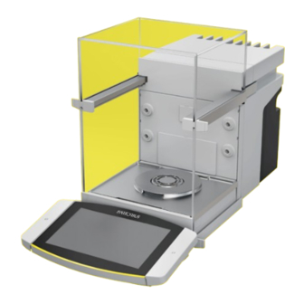
Device Description Device Description Device Overview Fig. 1: Cubis high-capacity micro balance, with motorized draft shield and 50 mm weighing pan (example) ® Pos . Name Description Weighing chamber Draft shield Cooling element Weighing module Contained in the housing. Leveling foot Motorically adjustable. Located on the bottom of the device. Proximity sensor Enables contact-free opening of the doors of a motorized draft shield. -
Page 14: Draft Shield
Device Description Draft Shield The draft shield can be opened motorically or manually, depending on the version of the device. When opening the draft shield, the top and side doors slide backwards. The top and side doors can be opened together or independently. -
Page 15: Components In The Weighing Compartment
Device Description Components in the Weighing Compartment Fig. 3: Components in the weighing compartment and 50 mm weighing pan (example) Pos . Name Description Rear wall of weighing compartment Guide for glass insert Available as an accessory. Ionizer nozzle The ionizer function must be activated in the control display. Base plate of weighing compartment Can be taken out, e.g. -
Page 16: Connections
Device Description Connections 3.4.1 Back of the Device Fig. 4: Connections on the back of the device, seal for conformity-assessed devices removed Pos . Name Description Slot For attaching a “Kensington” anti-theft device. USB-C connection For connecting accessories. USB-A connection For connecting accessories. -
Page 17: Rear Wall Of Weighing Compartment
Device Description 3.4.2 Rear Wall of Weighing Compartment Fig. 5: Connections on the rear wall of the weighing compartment, bezels removed Pos . Name Connection for an internal climate module Available as an accessory. Connection for the weighing compartment For accessories, e.g. motorized internal draft shield or base module sample holder. -
Page 18: Protective Caps And Covers For Connections
Device Description Protective Caps and Covers for Connections Fig. 7: Protective caps and covers on the rear wall of the weighing compartment, the back of the device and the operating display Pos . Name Description Cover for rear wall of weighing compartment Installed in the rear wall of the weighing compartment. -
Page 19: Conformity-Assessed Devices
Device Description Conformity-assessed Devices Some settings of conformity-assessed models are protected against operator changes, e.g. “external calibration”. This measure is intended to ensure the suitability of the devices for use in legal metrology. Accessories Accessories are available for the device. These enable the device to be customized to the specific conditions during weighing procedures, e.g. -
Page 20: Operating Design
Operating Design Operating Design Operating Elements in the Main Menu Fig. 8: Operating elements in the main menu (example) Pos . Name Description Navigation and function bar — Enables navigation and searching in menus and lists. — In the “Settings” Menu: Displays the name of the menu. Available tasks Displays all tasks available for the active user. -
Page 21: Operating Elements In Task Management
Operating Design Operating Elements in Task Management Fig. 9: Operating elements in Task Management (example) Pos . Name Description Navigation and function bar — Enables navigation and searching in menus and lists. — Enables the addition of tasks. — Opens the QAPP Center. —... -
Page 22: Operating Elements In The Weighing Display
Operating Design Operating Elements in the Weighing Display Fig. 10: Weighing display (example) Pos . Name Description Application symbol Displays the symbol for the active application. Task name Displays the name of the active task. Date display Displays the current date. Username Displays the name of the active user profile. -
Page 23: User Guide
Operating Design User Guide 4.4.1 Messages Fig. 11: Error message (example) Pos . Name Description Title Specifies the type of message, with or without error number. Description Specifies the cause. Solution Specifies the measures necessary to eliminate the cause of the message. Confirm Confirms and closes the message. -
Page 24: Advanced Operator Guidance
Operating Design 4.4.3 Advanced Operator Guidance Some applications have advanced operator guidance. The advanced operator guidance guides the user through the active task and comprises multiple switchable displays depending on the configured application: — First display: Shows the step currently being carried out as a graphic display. —... -
Page 25: Status Center
Operating Design Status Center Fig. 14: Status Center (example) Pos . Name Description Messages Displays information, warning, and error messages. Leveling status Displays the status of the level. Status for the device Displays the general device information. Calibration and adjustment report Displays the data for the last adjustment and calibration. -
Page 26: Keypad
Operating Design Keypad The keypad is intended for entering values in entry fields and is adapted to the selected language. If an entry field is activated: The alphanumeric keypad or numerical keypad appears. Fig. 15: Alphanumeric keypad and numerical keypad (example) Pos . -
Page 27: Buttons In The Operating Display
Operating Design Buttons in the Operating Display 4.8.1 Buttons for Navigation or Organization in Displays Symbol Name Description [Menu] button Quits the active task and opens the main menu. [Back] button — Returns to the previous display. — In the main menu: Accesses the last-performed task. [Search] button Displays options for browsing tasks and list elements. -
Page 28: Buttons For Editing Or Managing Entries
Operating Design Symbol Name Description [10 Positions Right] button Jumps 10 positions to the right in tasks or list elements. [Service Information] button Opens the “Settings”/“Device Settings”/“Device Service Information”/“Service” menu. Information [Status Archive] button Opens an overview of all status messages, warning Archive messages, and error messages. - Page 29 Operating Design Symbol Name Description [Deselect All] button Deselects the selection for all elements of a list. [Cancel] button — Cancels the current process without saving the changed settings or values. — In the display for editing the print memory: Marks the selected value as invalid.
-
Page 30: Buttons For Weighing, Printing, And Export Functions
Operating Design 4.8.3 Buttons for Weighing, Printing, and Export Functions Symbol Name Description [Leveling] button Opens the Leveling Wizard. [isoCAL] button Starts the isoCAL function. isoCAL [Result] button Toggles between the result and weight value display for the current application, e.g. weighing in percent. [Zero] button Starts zeroing. -
Page 31: Displays In The Operating Display
Operating Design Symbol Name Description [Result report] button If an application is active, e.g. density determination: Displays a report about the result of the application. [Export] button — Creates files depending on the context. — Releases the exported files, e.g., PDF or HTmL files, via a connector. -
Page 32: Applications And Tasks
Operating Design 4.10 Applications and Tasks QAPP applications (applications) are grouped together in QAPP packages. The device is supplied with some freely accessible applications in the “Essentials” QAPP package. These applications can be used to carry out the most important functions, such as weighing and calibration. Other applications may be activated in the QAPP Center for a fee. -
Page 33: Navigating The Menus
Operating Design 4.12 Navigating the Menus Procedure To open a menu: Press the button for the desired menu, e.g. the [Task Management] button. The menu opens and the name of the open menu is displayed in the navigation bar. To return to the main menu from other displays: Press the [Menu] button or press the [Back] button (multiple times) until the main menu is displayed. - Page 34 Operating Design If a value needs to be selected from a list: Scroll to the desired value in the display. To do this, swipe the display upwards or downwards. Press the desired value. To confirm the selection: Press the [OK] button. The selected value is saved and the list closes.
-
Page 35: Menu Structure
Operating Design 4.13 Menu Structure 4.13.1 Main Menu Navigating the menus (see Chapter 4.12, page 33). Level 1 Level 2 Level 3 Description Task Displays all available tasks. management Opens a summary of the properties for the displayed task. QAPP Center QAPP package —... -
Page 36: Settings" Menu
Operating Design 4.13.2 “Settings” Menu Depending on the approved applications, the device may display additional menus. Navigating the menus (see Chapter 4.12, page 33). Level 1 Level 2 Level 3 Description Device General device Displaces general device information, e.g. information information model name, serial number, QAPP Center version. - Page 37 Operating Design Level 1 Level 2 Level 3 Description Connections Connectors Display and manage the saved connectors, e.g. a USB stick. YDP30-NET If this extension has been configured in the QAPP Center: The connection to the FTP or FTPS FTPS servers facilitates file transfer using the FTP or FTPS protocol.
- Page 38 Operating Design Level 1 Level 2 Level 3 Description Connections SBI protocol Format Configure the settings for the data output and data output format. Output Define whether the output takes place with or without stability. Automatic data output Activate or deactivate the output rate for automatic data output.
- Page 39 Operating Design Level 1 Level 2 Level 3 Description Device Date and time NTP configuration Activate or deactivate time synchronization settings via NTP. Set the date and time Enter the date and time. Determine the time zone. Safe weighing isoCAL execution mode Set the isoCAL function.
- Page 40 Operating Design Level 1 Level 2 Level 3 Description Device Draft shield* Left/right palm key Set the function of the left and right palm settings key. Automatic mode If enabled: Closes the draft shield, carries out the function, and opens the draft shield again.
- Page 41 Operating Design Level 1 Level 2 Level 3 Description Sound (loudspeaker) Touch sounds Activate or deactivate the acoustic signal when operating a button. Message sounds Activate or deactivate the acoustic signal for messages. Sound for end-of-action Activate or deactivate the acoustic signal for the end of an action.
-
Page 42: Installation
Installation Installation Scope of Delivery Article Quantity Device Base plate of weighing compartment High-capacity micro balance: 50 mm weighing pan, slotted Shield plate for 50 mm weighing pan Power supply unit Country-specific power supply cable with test seal USB connection cable Operating display for Cubis ® Connection cable for operating display, installed on delivery 1 Draft shield Front panel Top door... -
Page 43: Selecting An Installation Site
Grip the device by the grooves (1) on the left and right-hand side and lift the device out of the bottom layer of foam packaging. Place the device down on a stable, completely flat surface. Sartorius recommends keeping the original packaging to return the device appropriately, e.g., for repairs. Attaching or Removing the Operating... -
Page 44: Placing The Device On Its Side And Installing
Installation Placing the Device on its Side and Installing For some installation work, the device has to be placed on its side, for example when inserting connection cables. Material: 1 soft support base, for placing down the device Requirement — There are no components installed in the pan retainer. —... -
Page 45: Inserting The Connection Cable For Ethernet
Installation Inserting the Connection Cable for Ethernet An Ethernet connection cable can be attached to the device. The Ethernet connection cable must be inserted into the cable channel on the side of the device. Material: 1 Ethernet connection cable Procedure Place the device on its side (see Chapter 5.5, page 44). -
Page 46: Installing The Draft Shield
Installation Installing the Draft Shield Procedure Remove the operating display from the device. Install the upper door. To do this, insert the two door panel mounts into the two guide rods on the side of the device and push backwards. Install the right and left doors. -
Page 47: Installing The Control Unit
Installation 5.10 Installing the Control Unit The control unit can be installed in front of or next to the device. Procedure Remove the operating display from the device. Place the control unit in the preferred position (for the dimensions for positioning the control unit, see Chapter “15.1 Dimensions and Weights”, page 79). -
Page 48: Getting Started
Getting Started Getting Started Attaching the Connection Cable for the Operating Display Procedure Insert the connection cable for the operating display into the recess in the rear side of the device (2). Plug the connection cable for the operating display into the “Operating display connection” (1) and screw tightly by hand. Attaching the Connection Cable for Ethernet Procedure Remove the operating display from the device. -
Page 49: Connecting The Power Supply
Procedure Check whether the country-specific power plug matches the power supplies at the installation site. If required: Contact Sartorius Service. Check whether the voltage specifications on the manufacturer’s ID label match those of the power supply at the installation site. -
Page 50: System Settings
System Settings System Settings Switching the Device On or Off If the device is being connected to the power supply for the first time, or after restoring the factory settings: The device is switched on and the Setup Wizard opens. All steps in the Setup Wizard must be completed. If the device is switched on after the Setup Wizard is complete and no passwords have been assigned for the user profiles: The user profile for the last user to be logged in is loaded. -
Page 51: Performing System Settings
System Settings Performing System Settings Default settings can be adjusted for the device and the applications in order to align with the ambient conditions and individual operating requirements. The following settings are necessary to operate the device together with connected components: —... -
Page 52: Activating Applications (Qapps)
System Settings To call up a structure in a help text: Press the [Info] button. The structure for the help text appears. The structure headings are links. Click on the desired heading. To export the help text: Press the [Export] button. The available connectors are displayed, e.g. -
Page 53: Activating Individual Applications From Qapp Package
System Settings 7.5.2 Activating Individual Applications From QAPP Package Procedure Press the desired application. A display opens containing details about the selected application. Press the [License] button. The input field for the license key appears. If an additional cost is associated with the application: Enter the license key in the entry field and press the [OK] button. -
Page 54: Configuring Motorized Opening And Closing Of The Draft Shield
System Settings Configuring Motorized Opening and Closing of the Draft Shield Pressing the palm-operated key on the operating display of the device enables the doors of the draft shield to be opened and closed motorically. The draft shield has a learning capability which enables the following opening parameters to be saved: —... -
Page 55: Changing User Profile Or User Role
System Settings 7.9.2 Changing User Profile or User Role For certain functions, the “User management” extension must be licensed in the QAPP Center. Procedure To change a user profile: Open the “Settings / User Management” menu. To change a user role: Open the “Settings / Access management / Role management”... -
Page 56: Setting Up Device For Network Printer
System Settings If a new entry needs to be created: Press the [New] button. The “Role management” display appears. Specify the desired settings in the “User management” menu and in the “Access management” menu. Confirm the entries. To do this, press the [OK] button. 7.10 Setting Up Device for Network Printer 7.10.1 Selecting Configuration for Network Printing... -
Page 57: Setting Up Device For Network Printer Via Company Network
System Settings Enter the router password under “Wi-Fi password”. The password is specified on the back of the Wi-Fi router. Press the [Back] button. The status “Ready” appears in the “Wi-Fi” overview display within 10 seconds. Creating a Network Printer Procedure Open the “Settings / Connections / Connectors / YDP30-NET”... -
Page 58: Configuring Print Profiles
Weighing and Print Profiles to a Task”, page 63). 7.11 Downloading Additional Information As part of the MCA firmware package on the Sartorius website, additional information is available for the device, e.g. a description of interface protocols, or a set of installation instructions for a website certificate. The information is available as a PDF file, partially in English. -
Page 59: Operation
Operation Operation Observing Warm-up Time After connecting to the power supply, the warm-up time must be observed. This enables the device to reach its required operating temperature and ensures accurate values during weighing processes. If this relates to a conformity-assessed device: The weight value is marked as invalid during the warm-up period. -
Page 60: Opening Or Closing Via Proximity Sensors
Operation 8.3.2 Opening or Closing via Proximity Sensors The proximity sensor works in “crossover mode”: — Left proximity sensor: Opens and closes the right-hand and the upper door — Right proximity sensor: Opens and closes the left-hand and the upper door The sensitivity of the proximity sensors can be adjusted (see Chapter “4.13.2 “Settings”... -
Page 61: Calibration, Adjustment Or Linearization
Operation Calibration, Adjustment or Linearization Function Description Calibration The device checks how much the displayed value deviated from the specified setpoint. Adjustment The device corrects the deviation to the setpoint. Linearization The device corrects the deviation from the ideal characteristic curve and the setpoint. -
Page 62: Internally Calibrating And Adjusting The Device
Operation Procedure If the isoCAL function is set to automatic start and the isoCAL function is triggered: The [isoCAL] button flashes in the operating display. Wait until the isoCAL function is executed. In the operating display, a time display counts down from 15 seconds to 0. -
Page 63: Creating A Task
Operation Creating a Task The QAPP applications must be configured in a task so that they can be executed, e.g. defining weighing and print profiles. Procedure Open the task. Press the [New] button. A list of the activated applications is displayed. To select an application: Press the desired application. -
Page 64: Weighing And Printing With Id Marking
Operation If a vessel is being used for the sample: Place the vessel for the material to be weighed onto the weighing pan. Press the [Tare] button. This compensates for the weight of the vessel. Place the sample in the vessel. If no vessel is used for the sample: Place the sample on the weighing pan. -
Page 65: Marking Saved Values As Invalid
Operation If additional values are to be saved: Remove the sample being weighed. Place the next sample on the weighing pan and press the [Save] button. Type or scan the sample ID into the entry field. Press the [OK] button. 8.9.2 Marking Saved Values as Invalid Procedure... -
Page 66: Printing Saved Values
Operation 8.9.4 Printing Saved Values Procedure Press the [Print Memory] button. The print memory opens and a list of all saved values is displayed. To start the print process using the print profile embedded in the current task: Press the [Print] button. A file, e.g. -
Page 67: Starting The Ionization Process
Operation Procedure Open the “Settings” / “Device Settings” / “Device Information” menu. Select the “View data storage device” menu item. A list of all the values saved in the data storage device is displayed. If only the values for a desired date need to be displayed: Press the [Filter] button. -
Page 68: Executing The "Statistics" Function (From"Essentials" Qapp Package)
Operation 8.12.2 Executing the “Statistics” Function (from“Essentials” QAPP Package) The “Statistics” application saves up to 1000 weight values and evaluates these statistically. The following values are saved and exported by the statistics application: — Number of components — Mean value — Standard deviation — Variation coefficient — Sum of all values —... -
Page 69: Cleaning And Maintenance
Cleaning and Maintenance Cleaning and Maintenance Preparing the Device for Cleaning Procedure If an accessory is connected to the device: Disconnect the accessory from the device (see instructions for the accessory). If the upper or lower cover for the rear wall of the weighing compartment is removed: Insert the cover for the weighing compartment into the rear wall of the weighing compartment (see Chapter 6.5, page 49). -
Page 70: Removing The Weighing Pan And Associated Components
— If there is a weighing pan with a shield plate: The shield plate (2) — Base plate of weighing compartment (3) Cleaning the Device Sartorius recommends cleaning the device at regular intervals, e.g. weekly. Do not allow deposits to form on the weighing pan. To clean the device, you can use the cleaning utensils supplied or a damp cloth, as well as the “Cleaning”... -
Page 71: Maintenance Schedule
USB mass storage device, taken from the Sartorius website. A software update can extend or change the functionality of the device. Sartorius recommends carrying out software updates: — Prior to starting the software updates, save the device data to a USB mass storage device. -
Page 72: Performing A Qapp Center Update
Cleaning and Maintenance Requirements The device is connected to the power supply. Procedure Download the software package from the Sartorius website onto the USB mass storage device. To do this, download the “Cubis ® Firmware” file. If this relates to a zip file: Unpack the software package on the USB mass storage device. - Page 73 Cleaning and Maintenance Procedure Download the QAPP Center package from the Sartorius website onto the USB mass storage device. To do this, download the “Cubis ® Firmware” file. If this relates to a zip file: Unpack the QAPP Center package on the USB mass storage device.
-
Page 74: Malfunctions
Hold down the palm-operated panel of the panel of the motorized draft shield is key. If the problem continues motorized draft not functional or is blocked. to occur: Contact Sartorius shield does not Service. open or close. Operating Instructions Cubis | MCA Models... -
Page 75: Decommissioning
Decommissioning Decommissioning 11.1 Decommissioning the Device Procedure Disconnect the device from the power supply. Disconnect the device from all connections at the installation site. If an accessory is connected to the device: Disconnect the accessory from the device (see instructions for the accessory). If the upper or lower cover for the rear wall of the weighing compartment is removed: Insert the cover for the weighing compartment into the rear wall of the weighing compartment (see Chapter 6.6, page 49). -
Page 76: Transportation
Transportation 12 Transportation 12.1 Transporting the Device Requirements — The device has been decommissioned. — The operating display is secured to the device. Procedure CAUTION Risk of injury when lifting or transporting! Disconnect the device from all connections at the installation site. Use both hands when transporting the device and setting it down. -
Page 77: Storage And Shipping
Transport damage as well as measures for subsequent cleaning and disinfection of the device or parts by Sartorius are charged to the sender. Devices contaminated with hazardous materials, e.g., harmful biological or chemical substances, will not be accepted for repair or disposal. -
Page 78: Disposal
Disposal 14 Disposal 14.1 Disposing of the Device and Parts The device and the device accessories must be disposed of properly by disposal facilities. A lithium cell battery, type CR2032, is installed inside the device. Batteries must be disposed of properly by disposal facilities. Procedure Dispose of the device in accordance with local government regulations. -
Page 79: Technical Data
Technical Data 15 Technical Data 15.1 Dimensions and Weights 15.1.1 High-capacity Micro Balance Unit Value Dimensions Dimensions (L x W x H) 501 x 240 x 301 Dimensions (L x W x H), with operating display removed 376.5 x 240 x 301 Weighing pan size (diameter) With operating display removed: Max. -
Page 80: Ambient Conditions
Technical Data 15.3 Ambient Conditions Unit Value Installation site Standard laboratory rooms Installation site according to IEC 60259-1, maximum altitude above 3000 sea level For indoor use only Air pressure, maximum mbar 600 – 1200 Temperature In operation °C +5 – +40 In operation, with isoCAL function* °C +10 –... -
Page 81: Electrical Data
Technical Data 15.5 Electrical Data 15.5.1 Power Supply Unit Value Power supply only permitted using Sartorius power supply unit Sartorius network device, type 1000099844 Power supply at installation site (primary) AC voltage 100 – 240 ± 10% Frequency 50 – 60... -
Page 82: Interfaces
Technical Data 15.5.4 Interfaces USB-A connection Communication: USB host (master) USB-B connection Communication: USB device (slave) Type of interface: Virtual serial interface (virtual COM-port, VCP) and “PC direct” communication USB-C connection Communication: Downstream-facing port (DFP), USB host (Master) Communication: RS232 connection with accessory YCC-USB-C-D09M 15.6 Wait Times Unit Value... -
Page 83: Recommended Calibration Weight
Technical Data 15.8 Recommended Calibration Weight 15.8.1 High-capacity Micro Balance Models MCA116S-3 | MCA36S-3 | MCA36P-3 MCA116S-3 MCA36S-3 MCA36P-3 Unit Value Value Value Resolution 0.002 0.001 0.01 | 0.001 Supported load 32 | 10 Recommended accuracy class External test weight Models MCA66S-3 | MCA66P-3 MCA66S-3 MCA66P-3... -
Page 84: Data Storage Device
Technical Data 15.10 Data Storage Device Value Maximum number of data records 150,000 15.11 Integrated Clock Unit Value Maximum deviation per month (RTC) 15.12 Backup Battery Unit Value Lithium battery, type CR2032 Service life at room temperature, minimum Years 15.13 Materials Housing Stainless steel 1.4401 | 1.4404, Aluminum Plastic PBT | PA... -
Page 85: Cleaning Agents And Cleaning Procedures
Technical Data 15.14 Cleaning Agents and Cleaning Procedures 15.14.1 Approved Cleaning Agents Cleaning agents and concentration Device Components Ethanol, Isopropanol, Citric Diluted Sodium Ecolab™ acid, hydrogen hydroxide, Klercide peroxide, Sporicidal 3.5% Chlorine Draft shield Top door Left and right doors Front panel Components in the weighing compartment... -
Page 86: Metrological Data
Technical Data 15.15 Metrological Data 15.15.1 High-capacity Micro Balance Models MCA116S-3 | MCA36S-3 | MCA36P-3 MCA116S-3 MCA36S-3 MCA36P-3 Unit Value Value Value Scale interval (d) 0.002 0.001 0.001 | 0.01 Maximum capacity (Max) 10.1 | 32 Repeatability at 5% load Standard deviation of the load 0.004 0.0015... - Page 87 Technical Data Models MCA66S-3 | MCA66P-3 MCA66S-3 MCA66P-3 Unit Value Value Scale interval (d) 0.001 0.001 | 0.01 Maximum capacity (Max) 12 | 61 Repeatability at 5% load Standard deviation of the load values, tolerance 0.0015 0.002 Repeatability at approx. maximum capacity Standard deviation of the load values, tolerance 0.004 0.01...
-
Page 88: Accessories
Accessories 16 Accessories This table contains a selection of the accessories that can be ordered. For information on other products, please contact Sartorius. Article Quantity Order Number Thermal transfer | thermal printer for GLP | GMP printouts on continuous YDP30 | YDP30-NET paper and labels Connection cable for operating display, length 3 m... -
Page 89: Sartorius Service
641,214 (90 mm x 32 mm x 8 mm) 17 Sartorius Service Sartorius Service is at your disposal for queries regarding the device. Please visit the Sartorius website (www.sartorius.com) for information about the service addresses, services provided, or to contact a local representative. For inquiries about the system or when contacting Sartorius Service in the event of a malfunction, ensure that you have the device information, e.g.,... - Page 90 EN 61010-1:2010 +A1:2019 +AC2014-04 Die Person, die bevollmächtigt ist, die technischen Unterlagen zusammenzustellen: The person authorised to compile the technical file: Sartorius Lab Instruments GmbH & Co. KG Electronics & Product Compliance 37070 Goettingen, Germany Sartorius Lab Instruments GmbH & Co. KG...
- Page 91 U U K K D D e e c c l l a a r r a a t t i i o o n n o o f f C C o o n n f f o o r r m m i i t t y y Sartorius Lab Instruments GmbH & Co. KG...
-
Page 92: Index
Index 20 Index Accessories........11, 19, 88 Data storage device ......84 Installation ..........42 Connecting ......... 49 Decommissioning ........75 Installation Conditions ......79 Acclimatization ........, 47 Device ............13 Intended Use ..........9 Adjustment..........61 Components in the Weighing Modifications to the Device ... 9 Calibration weight ...... - Page 93 Device ............10 Re-starting the System ......71 Safety Information on the Device ...10 Safety of Electrical Equipment ..81 Sartorius Service ........89 Scope of Delivery........42 Selecting an Installation Site ... , 79, 43 Setting up a Network Printer.... 56 Start-up ............50...
- Page 94 Sartorius Lab Instruments GmbH & Co. KG Otto-Brenner-Strasse 20 37079 Goettingen, Germany Phone: +49 551 308 0 www.sartorius.com The information and figures contained in these instructions correspond to the version date specified below. Sartorius reserves the right to make changes to the technology, features, specifications and design of the equipment without notice.
Need help?
Do you have a question about the Cubis MCA Series and is the answer not in the manual?
Questions and answers