Advertisement
User's
Manual
This user's manual describes the pulse output function (/P17 optional) of the WT500 power analyzer. To ensure
correct use, please read this manual thoroughly along with the WT500 user's manuals (IM760201-01E and
IM760201-17E).
1. Overview
/P17:
The pulse output function
The pulse output function outputs pulse signals in proportion to the active power and reactive power
measurements.
model:
Two input elements model (760202)
2. Specifications
2.1
Rear Panel
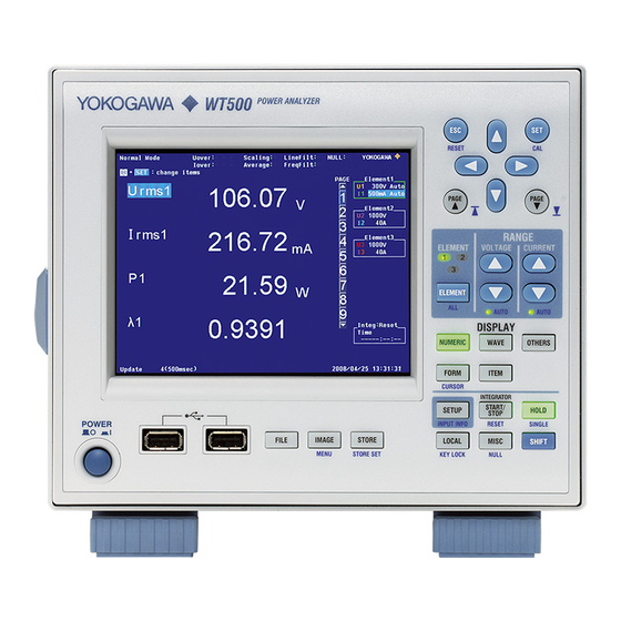
WT500 Power Analyzer
Pulse Output Function (/P17 Optional)
• Operation status LED that blinks while active power
standard pulse is being output
• Operation status LED that blinks while reactive power
standard pulse is being output
• Switches for changing the wiring system, current range,
scaling, and output format
• Active power reference pulse output connector
• Active power standard pulse output connector
• Reactive power reference pulse output connector
• Reactive power standard pulse output connector
1st Edition : September 2014 (YMI)
All Rights Reserved, Copyright © 2014 Yokogawa Meters & Instruments Corporation
Switch setting
→ ON
IM760201-52E
1st Edition
Advertisement
Table of Contents

Related Manuals for YOKOGAWA WT500


Summary of Contents for YOKOGAWA WT500
-
Page 1: Specifications
WT500 Power Analyzer Manual Pulse Output Function (/P17 Optional) This user’s manual describes the pulse output function (/P17 optional) of the WT500 power analyzer. To ensure correct use, please read this manual thoroughly along with the WT500 user’s manuals (IM760201-01E and IM760201-17E). - Page 2 Power-on Settings and Configuration Switches When the power is turned on, the voltage range is 100 V, the frequency filter is on, the key lock is on, the synchronization source is the voltage signal, and the current range and wiring are set to the values according to the following switch settings.
-
Page 3: Pulse Output Specifications
Pulse Output Specifications 2.3.1 Reference Pulse • Active power Single-phase three-wire, three-phase three-wire: 5000 pulse/kWs Single-phase two-wire: 10000 pulse/kWs • Reactive power Single-phase three-wire, three-phase three-wire: 5000 pulse/kvars Single-phase two-wire: 10000 pulse/kvars 2.3.2 Standard Pulse • Active power Single-phase three-wire, three-phase three-wire: 9/3.6 pulse/kWs Single-phase two-wire: 18/3.6 pulse/kWs •... -
Page 4: Current Characteristics
Active power pulse output accuracy: Within ±0.2% 2.3.7 Stability Settings: 100 V range, 5 A range, three-phase three-wire system 1) The difference between the maximum and minimum errors in the active power pulse output is within ±0.05% after measuring 20 times at 110 V, 5 A, 50 Hz, and a power factor of 0.5 (lag). 2) The difference between the maximum and minimum errors in the active power pulse output is within ±0.05% after measuring 20 times at 110 V, 5 A, 60 Hz, and power factor of 0.5 (lag). -
Page 5: Apparent Power
2.3.11 Temperature Characteristics Settings: 100 V range, 5 A range, three-phase three-wire system 1) At 110 V, 5 A, 50 Hz, and a power factor of 1, the difference in the active power pulse output errors at 10°C and 20°C and that at 20°C and 30°C are within ±0.1%. 2) At 110 V, 5 A, 50 Hz, and a power factor of 0.5 (lag), the difference in the active power pulse output errors at 10°C and 20°C and that at 20°C and 30°C are within ±0.1%.
Need help?
Do you have a question about the WT500 and is the answer not in the manual?
Questions and answers