Sign In
Upload
Manuals
Brands
YOKOGAWA Manuals
Measuring Instruments
WT500
YOKOGAWA WT500 Manuals
Manuals and User Guides for YOKOGAWA WT500. We have
3
YOKOGAWA WT500 manuals available for free PDF download: User Manual
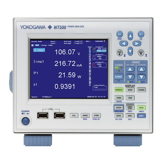
YOKOGAWA WT500 User Manual (360 pages)
Power Analyzer
Brand:
YOKOGAWA
| Category:
Measuring Instruments
| Size: 20.85 MB
Table of Contents
Product Registration
2
Checking the Package Contents
4
Input Element
4
Standard Accessories
5
Safety Precautions
7
Waste Electrical and Electronic Equipment
9
Conventions Used in this Manual
10
Workflow
11
Table of Contents
12
Front Panel
16
Rear Panel
16
Front Panel, Rear Panel, and Top Panel
17
Setup Menu Display and Operation Keys
18
And Pressing a Panel Keys Produces the Effect Indicated by the Purple Letters below It
22
Screen Display
23
Chapter 1 Component Names and Functions
24
Chapter 2 Features
24
System Configuration and Block Diagram
24
Block Diagram
25
Measurement Functions and Periods
26
Measurement Conditions
33
Power Measurement
39
Computation
42
Integration
45
Waveform Display
49
Trend, Bar Graph, and Vector Displays
56
Saving and Loading Data, and Other Miscellaneous Functions
59
Chapter 3 Before You Start Measuring
62
Handling Precautions
62
Installing the Instrument
64
Connecting the Power Supply
66
Turning the Power Switch on and off
67
Precautions for Wiring the Circuit that You will Measure
69
Assembling the Adapter for the Voltage Input Terminal
71
Wiring for Accurate Measurements
73
Guide for Selecting the Method Used to Measure the Power
74
Wiring the Circuit that You will Measure for Direct Input
75
Wiring the Circuit that You will Measure with a Current Sensor
78
Wiring the Circuit that You will Measure with a VT or CT
82
Setting the Date and Time
85
Initializing the Settings
87
Entering Values and Character Strings
88
Entering Character Strings on a USB Keyboard
90
Switching the Display
92
Displaying a List of Setup Parameters
94
Selecting the Message Language
95
Setting the USB Keyboard Language
96
Chapter 4 Measurement Conditions
97
Panel Keys and Setup Menus Used in this Chapter
97
Selecting a Wiring System
98
Selecting Independent Input Element Configuration
101
Setting the Measurement Ranges for Direct Input
103
Setting the Measurement Ranges for an External Current Sensor (Optional)
109
Setting the Scaling Feature When Using a VT or CT
112
Setting the Measurement Period
115
External Clock Input/External Start Signal Output Connector
116
Selecting an Input Filter
118
Selecting the Data Update Rate
120
Selecting an Averaging Method
122
Selecting a Crest Factor
125
Holding the Display and Performing Single Measurements
126
Chapter 5 Power Measurement
127
Panel Keys and Setup Menus Used in this Chapter
127
Displaying Numeric Data and Changing Displayed Items
128
Setting the Equations for Apparent and Reactive Power
137
Selecting a Phase Difference Display Format
139
Integration
141
Setting Manual Integration
146
Setting Normal or Continuous Integration
149
Setting Real-Time Integration or Real-Time Continuous Integration
152
Turning Integration Auto Calibration on or off
156
Selecting a Watt Hour Integration Method for each Polarity
157
Selecting a Current Integration Mode
158
Setting User-Defined Functions
159
Setting the MAX Hold Feature
164
Measuring the Average Active Power
166
Selecting What Frequency to Measure
167
Setting Delta Computation (Optional)
168
Chapter 6 Harmonic Measurement (Optional)
171
Panel Keys and Setup Menus Used in this Chapter
171
Changing Numeric Data Display Items
172
Selecting the PLL Source
178
Setting the Measured Harmonic Orders
180
Selecting a Distortion Factor Equation
182
Setting the Anti-Aliasing Filter
183
Displaying Bar Graphs and Making Cursor Measurements
185
Displaying Vectors
190
Chapter 7 Waveform Display
193
Panel Keys and Setup Menus Used in this Chapter
193
Displaying Waveforms
194
Selecting Which Waveforms to Display
195
Setting the Time Axis
196
Setting the Trigger
197
Setting the Trigger Level
200
Displaying Waveforms in Split Screens
203
Selecting a Graticule and Turning Interpolation, Scale Value Display, and Wave Labels on or off
205
Measuring with Cursors
213
Chapter 8 Trend Display
213
Panel Keys and Setup Menus Used in this Chapter
213
Displaying Trends
214
Selecting What Trend Data to Display
215
Setting Which Measurement Functions to Display Using Trends
216
Setting Trend Scaling
219
Setting the Time Axis
221
Displaying Trends in Split Screens
222
Wave Labels on or off
223
Restarting Trends
224
Measuring with Cursors
225
App
213
Chapter 9 Storing Numeric Data and Saving Stored Numeric Data
228
Panel Keys and Setup Menus Used in this Chapter
228
Setting the Storage Mode
229
Setting What Numeric Data to Store
230
Setting the Store Count, Store Interval, and the Scheduled Storage Start and End Times
232
Choosing Where to Store Numeric Data
235
Storing Numeric Data
240
Converting a Stored Binary Format File to CSV Format
242
Chapter 10 Saving and Loading Data
244
Panel Keys and Setup Menus Used in this Chapter
244
About USB Memory
245
Saving Setup Parameters, Waveform Display Data, and Numeric Data
247
Saving Screen Image Data
255
Loading Setup Parameters and Displaying File Properties
259
Deleting Files
262
Copying Files
265
Chapter 11 Ethernet Interface (Optional)
269
Panel Keys and Setup Menus Used in this Chapter
269
Connecting to a Network
270
Configuring TCP/IP Settings
271
Accessing the WT500 from a PC or Workstation (FTP Server Feature)
280
Checking the MAC Address and Whether the WT500 Is Equipped with the Ethernet Interface Option
283
Chapter 12 RGB Video Signal (VGA) Output (Optional) and Other Features
284
Panel Keys and Setup Menus Used in this Chapter
284
RGB Video Signal (VGA) Output (Optional)
285
Zero-Level Compensation
286
NULL Feature
287
Setting the Key and Shift Locks
288
Master and Slave Synchronized Measurement
289
Chapter 13 Troubleshooting, Maintenance, and Inspection
292
Troubleshooting
292
Error Messages and Troubleshooting Methods
293
Self-Test
297
Displaying the System Overview
300
Recommended Part Replacement
301
Chapter 14 Specifications
302
Input
302
Display
303
Normal Measurement Functions (Measured Items)
304
Accuracy
307
Functions
311
Data Storage
314
External Input and Output (Master and Slave Synchronization Signals and Clock Input)
316
RGB Video Signal (VGA) Output (Optional)
316
USB PC Interface
317
USB PERIPHERAL Interface
317
GP-IB Interface Option
317
Ethernet Interface Option
318
Safety Terminal Adapter
318
General Specifications
319
External Dimensions
320
Appendix
321
Appendix 1 Symbols and Determination of Measurement Functions
321
Appendix 2 List of Initial Settings and Numeric Data Display Order
328
Appendix 3 Power Basics (Power, Harmonics, and AC RLC Circuits)
334
Appendix 6 USB Keyboard Character Assignments
349
Advertisement
YOKOGAWA WT500 User Manual (110 pages)
Power Analyzer, Communication Interface
Brand:
YOKOGAWA
| Category:
Measuring Instruments
| Size: 1.97 MB
Table of Contents
USB Interface
2
Structure of the Manual
4
Symbols and Notation Used in this Manual
5
Table of Contents
6
Chapter 1 USB Interface
8
Names of Parts
8
USB Interface Functions and Specifications
9
Connection Via the USB Interface
10
Chapter 2 GP-IB Interface (Option)
11
Chapter 3 Ethernet Interface (Option)
18
App
20
Names and Functions of Parts
11
GP-IB Interface Functions
12
Connecting the GP-IB Cable
14
Setting the GP-IB Control
15
Responses to Interface Messages
16
Status Reports
83
Store Group
85
System Group
88
Waveform Group
90
Common Command Group
92
Chapter 4 Before Programming
21
A List of Commands
31
Index
23
Responses
25
Data
26
Synchronization with the Controller
28
Names and Functions of Parts
18
Ethernet Interface Functions and Specifications
19
Chapter 5 Communication Commands
31
Communicate Group
31
Cursor Group
31
Display Group
31
FILE Group
54
Harmonics Group
57
HOLD Group
58
Image Group
59
Input Group
61
Integrate Group
67
Measure Group
69
Numeric Group
73
RATE Group
82
Messages
21
Commands
23
Chapter 6 Status Reports
95
Status Byte
97
Standard Event Register
99
Extended Event Register
101
Output Queue and Error Queue
102
Appendix 1 ASCII Character Codes
103
Appendix
103
Appendix 2 Error Messages
104
Appendix 3 IEEE 488.2-1992
106
Index
108
YOKOGAWA WT500 User Manual (5 pages)
Power Analyzer Pulse Output Function (/P17 Optional)
Brand:
YOKOGAWA
| Category:
Measuring Instruments
| Size: 0.37 MB
Table of Contents
Specifications
1
Pulse Output Specifications
3
Current Characteristics
4
Voltage Characteristics
4
Apparent Power
5
Temperature Characteristics
5
Advertisement
Advertisement
Related Products
yokogawa WT5000
YOKOGAWA WT1800
YOKOGAWA WT310E
YOKOGAWA WT3001E
YOKOGAWA WT3002E
YOKOGAWA WT3004E
YOKOGAWA WT1801E
YOKOGAWA WT1805E
YOKOGAWA WT3000E
YOKOGAWA WT332
YOKOGAWA Categories
Measuring Instruments
Test Equipment
Transmitter
Controller
Media Converter
More YOKOGAWA Manuals
Login
Sign In
OR
Sign in with Facebook
Sign in with Google
Upload manual
Upload from disk
Upload from URL