Siemens XC1001-A Installation And Maintenance Manual
Extinguishing control unit xc10 series
Hide thumbs
Also See for XC1001-A:
- Installation, commissioning maintenance (76 pages) ,
- Operation (32 pages)

Related Manuals for Siemens XC1001-A


Summary of Contents for Siemens XC1001-A
- Page 1 XC10 Extinguishing control unit XC1001-A / XC1005-A / XC1003-A Installation Commissioning Maintenance Building Technologies A6V10257473_e_en_-- 2015-03-04 Control Products and System...
- Page 2 © Siemens Switzerland Ltd, 2015 We reserve all rights in this document and in the subject thereof. By acceptance of the document the recipient acknowledges these rights and undertakes not to publish the document nor the subject thereof in full or in part, nor to make them available to any third...
-
Page 3: Table Of Contents
XC1003-A ................... 14 FCP1004-E ..................15 XCM1002 .................... 16 User interface ..................18 Features ..................... 21 Installation ..................22 XC1001-A / XC1005-A ................ 22 XC1003-A ................... 24 User interface labels ................28 Connections ..................29 Mains ....................29 Batteries ....................29 Fire detectors/Manual release control buttons ........ - Page 4 Programming ..................58 12.1 Before starting ..................58 12.2 Presettings ..................59 12.3 Steps 01 to 04 - Time duration settings..........62 12.4 Step 05 - Sounders ................64 12.5 Steps 06 to 09 - Remote transmission ..........64 12.6 Steps 10 to 14 - Monitored outputs 1 to 5 ..........
- Page 5 Connection to Sinteso / Cerberus PRO panels ........ 90 18.1 XC10 zone ..................90 18.2 Detectors connected to XC10 panel ............ 91 18.3 Detectors connected to Sinteso / Cerberus PRO panel ......94 Maintenance PC ................97 Components and spare parts ............98 Building Technologies A6V10257473_e_en_-- Fire Safety...
- Page 6 Building Technologies A6V10257473_e_en_-- Fire Safety 2015-03-04...
-
Page 7: About This Document
About this document About this document Purpose of the document This document describes the installation, the commissioning and the maintenance of the XC100x-A equipment. It provides an overview of the structure and functions of the system as a whole as well as of the individual devices. While following the instructions, a reliable operation is assured. -
Page 8: Revision History
About this document Revision history Document no. Edition date Brief description A6V10257473_e_en_-- 03.2015 - MP2.3 SR2 A6V10257473_d_en_-- 04.2012 - MP2.3 SR1 A6V10257473_c_en_-- 09.2010 - chap. 4.5 updated (fig. 5 and table) - chap 7.2.1 added: method for calculation of the battery capacity - chap. -
Page 9: Safety Instructions
Safety instructions Safety instructions Danger levels The following pictograms indicate the possible danger levels, their severity and consequences. Imminent danger! DANGER è Serious injuries or death. Potentially dangerous situation WARNING è Serious injuries or death. Potentially dangerous situation CAUTION è Light injuries or material damage. -
Page 10: Standards And Directives Complied With
Personal injury or damage to property caused by poor maintenance or lack of maintenance Standards and directives complied with A list of the standards and directives complied with is available at your Siemens contact partner. Building Technologies A6V10257473_e_en_--... -
Page 11: Standards
Standards Standards In addition to the requirements of EN12094-1 and EN54-2, the XC100x-A control panel complies with the following optional functions: EN 12094-1 Clause Description 4.17 Delay of extinguishing signal 4.18 Signal representing the flow of extinguishing agent 4.19 Monitoring the status of components 4.20 Emergency hold device 4.21... -
Page 12: Overview
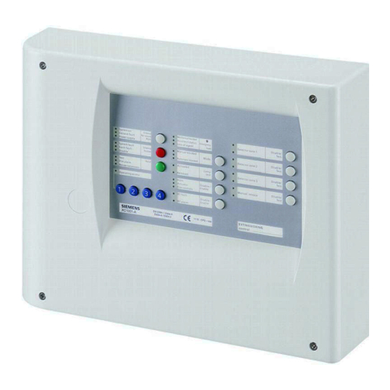
Overview Overview The equipment is declined in 3 versions: Wall mounting cabinet: XC1001-A / XC1005-A 19” rack cabinet: XC1003-A XC1001-A System ON Mechanical blocked Silence Detector Zone 1 Disable Fault Re-sound Incorrect status Emergency Test Power supply Sounders Loss of agent hold …………………………………. -
Page 13: Xc1005-A
Overview XC1005-A Fig. 2 XC1005-A FCP1004-E power supply unit with charger XCM1002 mainboard 17 A/h batteries DIN rail for accessory mounting (Z3B171 relay module) FDCI / FDCIO222 module for the connection to a fire detection system (option) Building Technologies A6V10257473_e_en_-- Fire Safety 2015-03-04... -
Page 14: Xc1003-A
Overview XC1003-A Fig. 3 XC1003-A FCP1004-E power supply unit with charger XCM1002 mainboard Removable mainboard holder 4.5 A/h or 7.2 A/h batteries DIN rail for accessory mounting (Z3B171 relay module, XCA1030 multi-sector modules, etc.) FDCI / FDCIO222 module for the connection to a fire detection system (option) Building Technologies A6V10257473_e_en_--... -
Page 15: Fcp1004-E
Overview FCP1004-E Fig. 4 FCP1004-E power supply unit Mark Function Remarks Mains voltage setting Shunt ON = 115V , shunt OFF = 230V Mains terminal block Mains fuse 4A / 250V System start without mains power Shunt the 2 terminals with a jumper and remove after system start Temperature sensor for battery charging voltage compensation Do not cover... -
Page 16: Xcm1002
Overview XCM1002 X27 1 Fig. 5 XCM1002 board Setting elements Internal buzzer Enable/Disable Jumper up (factory setting) : buzzer enabled Jumper down : buzzer disabled (only for servicing) Type of power supply Jumper up (factory setting) : FCP1004-E Jumper down : do not use (for further use of external power supply) Operating access Level 2 Jumper on the left: Level 2 permanent access 1 –... - Page 17 Overview PCB terminal blocks Plug-in block 6 points 1-2 (–) / 5-6 (+) 24V power supply (1.5 mm max.) 3-4 (+) Power supply monitoring Plug-in block 4 points 1 (+) / 2 (–) Monitored output 5 (2.5 mm max.) 3 (+) / 4 (–) 24V use output Plug-in block 4 points 1 (+) / 2 (–)
-
Page 18: User Interface
Overview User interface All display and control elements, except 4-digit display for XC1001-A version, are accessible to the user: Led 1 to 32 indicators for operating condition, Keys 1 to 15 allowing : operating access è operation (reset, off, test, etc) è... - Page 19 Overview Indicators State Description N° Color Yellow Fixed – Manual release is blocked or being tested Yellow Fixed Standard = not used – Alternative = automatic and manual release granted (UK) – Yellow Fixed – Automatic release is blocked At least one detection zone which starts the extinguishing is off or being tested –...
- Page 20 Features Keys Description 1 … 4 Operating access code input (level 2, programming, system test, etc.) è When operating access level 2 is selected, if the code is entered again, the system returns to the level 1, without waiting for the end of the 4 minutes timeout Silence / Restart sounders by successive pressing: 1st pressing: silence sounders...
-
Page 21: Features
SELV (Safety Extra Low Voltage) Detection lines Type / number of detectors Collective / 32 max. (according to detector type) Compatible detectors Siemens (Algorex, Sinteso, Synova, Cerberus FD110 End of line element (EOL) series) Standby condition voltage / current Transzorb 18 V (P6KE18CA) Alarm condition voltage / current 17.1 …... -
Page 22: Installation
3. Fix the chassis using 3 screws Ø 4 x 50 mm (not provided) 4. Cut out the cable entries 5. Cut out the plastic housing according to the cable inputs (XC1001-A) 6. Mount the cable glands if necessary (required for protection rating IP30) 7. - Page 23 Installation 3 (insert in slot 4) 12 V – 12 Ah batteries 12 V – 17 Ah batteries FCA1014 battery holder (option) Slot for battery holder Fig. 8 XC1005-A, battery installation Building Technologies A6V10257473_e_en_-- Fire Safety 2015-03-04...
-
Page 24: Xc1003-A
Installation XC1003-A Fix the XC1003-A into a 19'' housing cabinet with a protection rating IP ≥ 30. Fig. 9 XC1003-A, mounting examples The interval between 2 extinguishing racks and there power supply rack should not exceed 12U. Building Technologies A6V10257473_e_en_-- Fire Safety 2015-03-04... - Page 25 Installation XC1003-A, mounting adaptation The 19” rack is symmetrical. This allows, with some mounting/unmounting operations, to adapt it to various configurations (2 racks minimum are necessary). Remove parts 1, 2, 3 & 4 from rack A Remove parts 5 & 6 from rack B Reassemble parts 5 &...
- Page 26 Installation XC1003-A, commissioning / connection / maintenance The removable board holder (1) can be positioned, after screw unmounting (3), as indicated below to reach the DIN rail (2). Fig. 11 XC1003-A, removable stand in “Commissioning” position Building Technologies A6V10257473_e_en_-- Fire Safety 2015-03-04...
- Page 27 Installation XC1003-A, batteries installation 4.5 Ah batteries: 1. Remove the holder (1) 2. Install the batteries (3) as shown below 3. Remount the holder (1) 7.2 Ah batteries: 1. Remove the parts (1) and (2) 2. Install the batteries (4) as shown below Fig.
-
Page 28: User Interface Labels
Installation User interface labels Insert the labels following the instructions on the board provided with the equipment. XC1001-A Pos. 1 Pos. 3 Pos. 7 XC1003-A XC1005-A Stripe EN A5Q00034729A-03 System ON Silence Detector Zone 1 Disable Detector Zone 1 Disable... -
Page 29: Connections
Two 12 V batteries, connected in series, can be connected with the FCP1004-E power supply. According to the control units, the following batteries can be installed: XC1001-A : 4.5 Ah XC1005-A : 4.5 Ah, 7.2 Ah, 12 Ah or 17 Ah XC1003-A : 4.5 Ah or 7.2 Ah Fig. - Page 30 Connections 7.2.1 Battery capacity calculation Battery capacity must be calculated according to the following formula: = ((I ) + (I )) * K Batt R total A total : battery capacity (Ah) Batt : operating current, internal and external in standby condition (A) R total : operating current, internal and external in alarm condition (A) A total...
-
Page 31: Fire Detectors/Manual Release Control Buttons
Connections 2 fire controls, solenoid 3 W à door contact for ex.(125mA each) – 2 repeaters XT1001-A1 powered by XC10 – Battery capacity calculation for 12, 24 and 72 hours backup time, followed by an alarm condition during 15 mn: è... - Page 32 Connections Fig. 15 XC100x-A, connection of detectors and manual triggering devices The number of detectors which can be connected is determined by dividing the collective system line connection factor (KLK = 32) by the collective element load factor (KMK = see table below). Series of detectors Designation ALGOREX...
-
Page 33: Monitored Inputs
Connections 7.3.2 Wiring for explosion hazard areas Fig. 16 Wiring for explosion hazard areas In ex-areas, use only fire detectors that are approved for ex-areas. Between the explosion-hazard area and the non-ex-area, the detector line must be galvanically insulated (DC1192) and laid via a safety barrier (SB3). The termination element EOL22Ex must be provided as line terminator. - Page 34 Connections 7.4.1 Monitored input 1 This input is exclusively reserved for the connection of the extinguishing discharged contact. Operation is defined at programming step 28. Fig. 17 XC100x-A, monitored input 1 connection Discharged contact normally closed (NC) Discharged contact normally open (NO) No contact connected (3.3kΩ...
-
Page 35: Control Inputs
Connections 7.4.4 Monitored input 4 This input can be used for several purposes. Operation is defined at programming step 31. Fig. 20 XC100x-A, monitored input 4 connection Emergency abort Emergency hold Automatic blocked / Manual blocked / Automatic and manual blocked Not used (3.3kΩ... -
Page 36: Monitored Control Outputs
Connections Monitored control outputs Five monitored control outputs are available on terminal blocks X7, X6 and X5 for the connection of various devices. Technical data for control outputs 1 to 3 activation by reverse polarity (polarities indicated are “activated” polarities, according to connected device, a diode can be necessary) line monitoring: 3.3 kΩ... - Page 37 Connections 7.6.1 Monitored control output 1 This output is exclusively reserved for the connection of the Sounders. Operation is defined at programming steps 05 and 10 (see paragraphs 12.4 and 12.6). Fig. 22 XC100x-A, monitored control output 1 connection Sounders Control output not used (no EOL required) 7.6.2 Monitored control output 2...
- Page 38 Pyrotechnic actuators 1 to 10 actuators maximum, connected in series, can be connected. The table below indicates max. line lengths, in meters, according to cable section for the Siemens Monopist pyrotechnic actuator : MONOPIST / code A6E60200462 1.5 mm 1067 2.5 mm...
-
Page 39: Programmable Outputs
Connections Option 01 at step 02 must be imperatively selected in case of pyrotechnic actuator and not be selected in case of electromagnetic actuator. 7.6.5 Monitored control output 5 This output can be used for several purposes. Operation is defined at programming steps 01, 03, 14, 63 and 64 (see paragraphs 12.3, 12.6 and 12.6). - Page 40 Connections Fig. 27 XC100x-A, driver outputs connection Theses outputs are intended to control external relays like Z3B171, for example: Shutting down the ventilation system Closing the extinguishing area doors Closing the fire dampers Status information’s All relays must be installed inside the control unit. 7.7.2 Relay outputs Five potential-free contacts, including 4 programmable (1, 2, 4 and 5), are available...
- Page 41 Connections Fig. 28 XC100x-A, relay outputs connection Building Technologies A6V10257473_e_en_-- Fire Safety 2015-03-04...
-
Page 42: Power Supply Output
Connections 24V power supply output A 24V power supply output, protected by fuse 1 AT (F3), is available on terminal block X5-3 (+) / X5-4 (-) to power various devices (internal or external). When the fuse F3 is blown, a general fault indication is displayed (see paragraph 14.2 for details). Repeater terminal and repeater display The repeater terminal/display must be connected to X12-9/10 (RS485 RTnet connection). -
Page 43: Multi-Sector Installation
Multi-sector installation Multi-sector installation Multi-sector extinguishing systems are capable of protecting several flooding zones. The basic setup consists of one common cylinder bank. To this cylinder bank, a piping network is connected to every flooding zone by means of selector valves. - Page 44 Multi-sector installation Remote transmission to Monitored input Control line 5 fire brigade Discharged XCA1030 / XC10 n°1 XC10 n°1 Flooding zone 1 contact Small room (1 cylinder) Selector valve Solenoid valve Mechanical 19" cabinet (opens selector blocking device valve) (option) Manual release DM1103-L XC1003-A...
-
Page 45: Detailed Description
Multi-sector installation Detailed description 8.2.1 XCA1030 & XCA1031 connection BORA Box Actuator 3.3kΩ line 1 Redundant actuator lines Actuator 3.3kΩ line 2 Control cylinder 3.3kΩ XCA1031 Loss of agent multi-sector common line module AXICOM AXICOM Activation line Contact resistor is included in XCA1030 Multi - sector bus XCA1030... - Page 46 Multi-sector installation The activation line output (contact resistor) is activated as soon as the XC10 is switched to the activated condition. This output is used to inform the XCA1031 common module that one XC10 is activated. The multi-sector bus is a one way RS485 communication from the XCA1031 module to XCA1030 modules.
- Page 47 Multi-sector installation affected. All manometer or weighing devices must be connected to the XCA1031 loss of agent line (control cylinder and main cylinder bank). All contacts must be connected in series (special cables connection are available: TOR-UNIT, TOR- MULTI, TOR-END). Normally closed contact must be used (i.e pressure or quantity of gas is correct when the contact is closed).
-
Page 48: Installation And Wiring
Multi-sector installation Installation and wiring Multiple flooding zones modules are mounted on a DIN rail: XCA1031 : in the 19" cabinet where XC1003-A control units are installed XCA1030 : in each XC1003-A (see Fig. 3) The drawing below shows a connection example between XCA1030 modules and the XCA1031 for a 3 flooding zones installation. -
Page 49: Modules Technical Specification
Multi-sector installation Modules technical specification XCA1030: Selector valve position monitoring input: line monitoring: 3.3 kΩ resistance connected at the end of the line contact resistor: 1.2 kΩ line resistance: 80 Ω max. XCA1031: Actuator line 1 and 2: device can be either electromagnetic or pyrotechnic actuator activation by reverse polarity (polarities indicated are “activated”... -
Page 50: Accessories
Accessories FCA1007 – Key switch This device, only usable with XC1001-A and XC1005-A control panel, is connected to the terminal block X8 of XCM1002 mainboard (see paragraph 4.5) and allows operating access level 2 access per key rather than by code: the use must be defined by programming (see paragraph 12.15) -
Page 51: Repeaters
Accessories Repeaters 9.4.1 Description The repeater connects to the XC10 extinguishing control panel and provides remote status indication and remote control. Up to 16 repeaters can be connected to each XC10 control panel The number of repeaters connected to an XC10 is configured with programming step 60 Data transmission path called RTNet is using RS485 physical layer Maximum line lengh: 1200 m... - Page 52 Accessories Technical data: - Power supply voltage range: 8 … 30V - Current consumption: standby condition: 12 mA alarm condition: 20 mA - Operating / Storage temperature: -5°C … +40°C / -10°C … +60°C - IP rating: IP40 - Dimensions (l x h x p) : 210 x 200 x 48 mm - Weight : XT1001-A : 510 g / XT1002-A : 625 g 9.4.2 User interface...
- Page 53 Accessories Key N° Description Silence internal buzzer è Operating access level required for this operation: level 1 or level 2 è This operation silences the repeater buzzer only, not the XC10 buzzer Led and buzzer test (duration = 5 seconds): All led indicators are switched on and the internal buzzer sounds continuously è...
- Page 54 Accessories 9.4.4 Connections and configuration Repeaters can be powered directly from the XC10 24V output or from an external power supply. Wiring depends on the type of power supply connection: XT/XTA100x-A1 XT/XTA100x-A1 XT/XTA100x-A1 N° 1 N° 2 N° 16 XC100x-A (XCM1002) XT/XTA100x-A1 XT/XTA100x-A1...
- Page 55 Accessories Configuration SW5 : shall be switched to « ON » position on the last repeater of the RTNet – line, shall be switched to « OFF » position on all others repeaters SW3 : rotary switch for setting the repeater address (any address change shall –...
-
Page 56: Operating Access Levels
Operating access levels Operating access levels XC100x-A equipment operation is organised in several operating access levels. 10.1 Operating access level 1 This level gives access to: silence buzzer (see programming options in step 56) led test fault detailed display alarm counter display (XC1003-A and XC1005-A only) 10.2 Operating access level 2 This operating access level gives access, after code input on keyboard (4 2 3 3 by... -
Page 57: Extinguishing Process Diagrams
Extinguishing process diagrams Extinguishing process diagrams The following diagrams show the execution of an extinguishing process initiated by an automatic activation, a manual release and a mechanical release on the cylinders (optional). Fig. 39 Extinguishing process initiated by automatic detectors Fig. -
Page 58: Programming
Programming Programming 12.1 Before starting Some of the programming options are entitled « Processing as ». This means that an output, programmed with this option, will function in the same way: Processing as : Description RT-alarm Output can be disabled via key 11 (“Disable RT-Alarm”) Output line fault is reported on “RT-alarm”... -
Page 59: Presettings
Programming Navigation in programming Programming is carried out using the « Silence buzzer » (6), « Reset » (7), « Mode select » (8), « Led test » (9) keys and the 4-digit display: The “Silence buzzer” key (6) allows scrolling the steps ahead, the “Reset” (7) key scrolling back The “Mode select”... - Page 60 Programming 6. Press and hold down the keys “1” to “4” of the keyboard to validate The validation of a country presetting (whatever it is) implies that any modification (of one or some of the programming options) will be cancelled and replaced by the options of this presetting. Presettings and corresponding options Building Technologies A6V10257473_e_en_--...
- Page 61 Programming Presettings and corresponding options Building Technologies A6V10257473_e_en_-- Fire Safety 2015-03-04...
-
Page 62: Steps 01 To 04 - Time Duration Settings
Programming 12.3 Steps 01 to 04 - Time duration settings Option Step Description Pre-discharged warning time for automatic release (check programming step 65 for manual release) The Pre-discharged warning time sets the countdown duration before the actuator extinguishing release triggering. During this time, the reset function is not possible. - Page 63 Programming 300 seconds (5mn) 5mn 30s 6mn 30s 7mn 30s 8mn 30s 9mn 30s 10mn 11mn 12mn 13mn 14mn 15mn 16mn 17mn 18mn 19mn 20mn 21mn 22mn 23mn 24mn 25mn 26mn 27mn 28mn 29mn 30mn Until "Reset" Monitored output 5 : activation duration Applicable, with the same options as at step 02, only if this output is set to “Process as actuator”...
-
Page 64: Step 05 - Sounders
Programming 12.4 Step 05 - Sounders Option Step Description Sounders: program the pattern Fire alarm Activated Emergency hold/abort Released Continuous Pulsated fast Pulsated slow Pulsated fast Pulsated slow Pulsated fast Pulsated slow Continuous Pulsated fast Pulsated long Pulsated fast Continuous Pulsated slow Continuous Pulsated slow... -
Page 65: Steps 10 To 14 - Monitored Outputs 1 To 5
Programming Remote transmission blocked Application: avoid the remote transmission when the system is controlled by the operator 12.6 Steps 10 to 14 - Monitored outputs 1 to 5 Option Step Description Monitored output 1 : select the operation Processing as “Sounders” (see step 05 and paragraph 12.1) Active until “Silence/Re-sound”... -
Page 66: Steps 15 To 19 - Relay Contact 1 To 5
Programming Active in state “Automatic Blocked” Active in state "Manual blocked” Active in state "Automatic blocked” or "Manual blocked" Active in state "Automatic blocked” and "Manual blocked" Active in state "Emergency hold/abort" Processing as "Sounders", follows the activation of monitored output 1 (see steps 05 and 10 and paragraph 12.1) Active in state "Fire alarm"... -
Page 67: Steps 20 To 27 - Driver Outputs 1 To 8
Programming Processing as “Sounders” (see steps 05 and 10 and paragraph 12.1) Active in state "Selector valve opened" (XCA1030 multi-sector module) Active in state "Extinguishing activated from electrical manual release" Active in state "Extinguishing activated from automatic detectors" Active in state "Extinguishing activated from remote activation" Active in state "Fault"... -
Page 68: Steps 28 To 31 - Monitored Inputs 1 To 4
Programming Active in state: - “Manual blocked” - Zone 4 in fault condition - “Processing as actuator” control lines in fault condition - Actuator disabled Active in state Zone 1 alarm condition until “Reset” Active in state Zone 2 alarm condition until “Reset” Active in state Zone 3 alarm condition until “Reset”... - Page 69 Programming Contact (1.2 kΩ) normally opened when cylinders pressure/weight is correct No contact (EOL resistor not required) Monitored input 3 : select the function Mechanical blocking device: Contact (1.2 kΩ) closed + contact (680 Ω) opened = "Normal" – Contact (1.2 kΩ) opened + contact (680 Ω) closed = "Mechanical blocked" –...
-
Page 70: Steps 32 To 38 - Reset
Programming Emergency hold -EN 12094-1 4.20.3 b) compliant Contact (1.2 kΩ) opened during pre-discharged warning time = extinguishing process is hold as long as the contact is – maintained opened. When contact is released, pre-discharged warning time restarts Contact (1.2 kΩ) opened after actuator activation = no effect –... -
Page 71: Steps 44 To 47 - Faults
Programming One second beep at each "Emergency hold/abort" change Pulsated until "Silence buzzer" Pre-activated condition: select the function in case "Automatic blocked" operation Alarm on one of the extinguishing triggering zones = "Fire alarm" + "Pre-activated" until "Automatic blocked" condition is cancelled or "Reset"... -
Page 72: Steps 52 To 55 - Detection Zones
Programming 1) 3) "Manual blocked" 1) 3) "Automatic and manual blocked" External device disabled "RT-Alarm" and "RT-Fault" disabled External device fault (“Reset” operation is required to eliminate the fault indication) External power supply fault Fault on "RT-Fault" line from external device remote transmission (transmitter, for example) 1) 3) Level 2 operating access 2) 3) -
Page 73: Steps 56 To 57 - Operating Access Level
Programming 12.15 Steps 56 to 57 - Operating access level Step Option Description "Silence buzzer": change access level Possible at access levels 1 and 2 Possible at access level 2 only Access level 2 Default code = 4 2 3 3 Individual access code: 1. -
Page 74: Step 62 - Loss Of Agent In Multi-Sector Application
Programming Configure Repeater silence buzzer Silence buzzer on XC10 do not silence buzzer on repeater terminal Silence buzzer on XC10 silences buzzer on repeater terminal 12.19 Step 62 - Loss of agent in multi-sector application Option Step Description XCA1031 loss of agent contact programming Contact (1.2 kΩ) normally closed when cylinders pressure/weight is correct Contact (1.2 kΩ) normally opened when cylinders pressure/weight is correct 12.20 Steps 63 to 64 - Fire damper... -
Page 75: Step 65 To 66 - Pre-Discharged Warning Time In Manual Release
Programming 50 seconds 55 seconds 1 minute 1 mn 10 s 1 mn 20 s 1 mn 30 s 1 mn 40 s 1 mn 50 s 2 mn 2 mn 10 s 2 mn 20 s 2 mn 30 s 2 mn 40 s 2 mn 50 s 3 mn... -
Page 76: Step 67 - Operation If "Discharge" Is Activated In Standby
Programming 100 seconds 105 seconds 110 seconds 115 seconds 120 seconds Same as pre-discharged warning time of automatic release Configure Manual Release “pre-discharge” warning time to overwrite Automatic release “pre-discharge” warning time Manual release “pre-discharge” warning time does not overwrite Automatic release “pre-discharge” warning time Shorter Manual release “pre-discharge”... -
Page 77: Commissioning
Commissioning Commissioning Before commissioning, ensure that: the control unit is correctly mounted on a fixed support all detector bases are correctly connected all monitored lines are correctly connected and equipped with respective EOL all accessory or optional parts are present FCP1004-E power supply setting correspond to the mains voltage mains voltage is available batteries are installed, but not connected yet... -
Page 78: System Test
Commissioning 13.3 System test 1. check the extinguishing process by automatic and manual activation 2. check display of "Released" condition 3. check the pre-discharged warning time 4. check sounders and warning panels operation 5. check RT-Alarm and RT-Fault 6. check fire controls operation 7. -
Page 79: Maintenance
Maintenance Maintenance 14.1 Preventive maintenance 14.1.1 Performed by the customer Once a week Check that all leds and buzzer are activated with the "Led test" 14.1.2 Performed by the maintenance technician The maintenance operation of an extinguishing installation must be performed by a qualified and trained technician who is familiar with XC10 control panel and knows all the risks relating to extinguishing. - Page 80 Maintenance Inform the person in charge of the building security about the type of maintenance operation planned and the duration. Switch the mechanical blocking device to the position "Blocked" (if existing). Switch the XC10 to the "Test mode" (Z1 to Z4). Disconnect the actuator electrical line by removing the connector from the BORA box (or equivalent).
- Page 81 Maintenance parameters. Activate the discharged contact (if existing) and reset the panel. Activate the manual release with the DM1103-L button. Check the pre- discharged warning time, the activation of warning panels, sounders, and fire controls. Ensure that sounders are audible from each side of the room. Reset the panel.
-
Page 82: Detailed Fault Display
Maintenance 14.2 Detailed fault display Press simultaneously keys “1” and “3” of the numeric keypad: Faults appear for 10 seconds according to the table below è OL: Open Line SC: Short Circuit System ON Mechanical blocked Silence Detector Zone 1 Disable Re-sound Incorrect status... - Page 83 Maintenance Mechanical blocked System ON Silence Detector Zone 1 Disable Fault Re-sound Incorrect status Test Emergency Sounders …………………………………. Enable Power supply Loss of agent hold Manual blocked System fault Detector Zone 2 Disable Silence Earth fault Mode Test buzzer …………………………………… Enable Disable Automatic blocked...
-
Page 84: Test Functions
Test functions described in this chapter are only possible when the equipment is in standby condition (=no alarm). If an alarm occurs, the test ends immediately. In order to access the 4 digit display, the XC1001-A plastic cover must be removed. 15.1 Led test Press the «... -
Page 85: Rt-Alarm Test
Test functions 15.4 RT-alarm test Procedure 1. Enable operating access level 2 2. Press and hold down key « 3 » on numeric keypad then press the « Silence / Re-sound sounder » key (5): RT-alarm outputs are enabled for 30 seconds «... -
Page 86: Individual Output Test
Programming access is not possible Connection with the maintenance PC cannot be enabled Procedure 1. Remove the front plastic cover (XC1001-A) 2. Enable operating access level 2 3. Press and hold down the key « Silence buzzer » (6), then enter the code 3 4 2 1 1 2 on the keypad: è... -
Page 87: Zone Test
Test functions 15.8 Zone test Zone test is used to check each connected detector. Procedure 1. Enable operating access level 2 2. Press 2 times the key "Disable/Test/Enable" (12 to 14) corresponding to the zone to be tested: è The yellow led of the zone (26, 28, 30) and the yellow led "Test" (7) flash slowly è... -
Page 88: Advanced Functions
Advanced functions Advanced functions The functions described in this chapter require to remove the front plastic cover of the XC1001-A variant . 16.1 Checksum This function is used to check if a programming modification was carried out: Procedure 1. Enable operating access level 2 2. -
Page 89: Special Functions
Special functions Special functions The functions described in this chapter must be used only during commissioning and/or maintenance. It is not allowed to use these functions during normal operation. The following access code shall not be delivered to the customer. 17.1 Anticipated Silence Sounders This function is used to stop/start the Sounders during the pre-discharged warning... -
Page 90: Connection To Sinteso / Cerberus Pro Panels
Connection to Sinteso / Cerberus PRO panels Connection to Sinteso / Cerberus PRO panels The XC10 control panel can be integrated into a Sinteso / Cerberus PRO fire detection system. This integration offers the possibility to: send XC10 status to the fire control panel transmit commands from the fire control panel to the XC10 The integration uses IO modules connected to the FDnet (FDCI222 / FDCIO222 / FDCIO224). -
Page 91: Detectors Connected To Xc10 Panel
Connection to Sinteso / Cerberus PRO panels Sinteso / Cerberus PRO operating terminal when the “XC10 zone” element 4:Input ‘Blocked’ is activated Resetable from Sinteso / Cerberus PRO If this option is selected, the “XC10 zone” element 1:Output ‘Reset’ is activated for 3 seconds each time a “Reset”... - Page 92 Configuration example using FXS engineering tool: Create an XC10 zone: 1. create an area named “Siemens Training Center” 2. create a section named “Room Spirit 1” 3. under this section a. create an XC10 Zone named “Extinguishing”...
- Page 93 For this variant, Step 37 option 02 must be selected CAUTION Configuration example using FXS engineering tool: Create an XC10 zone: 1. create an area named “Siemens Training Center” 2. create a section named “Room Spirit 1” 3. under this section a. create an XC10 Zone named “Extinguishing”...
-
Page 94: Detectors Connected To Sinteso / Cerberus Pro Panel
Connection to Sinteso / Cerberus PRO panels b. select “Autom. exting. release blockable from Sinteso / Cerberus PRO” c. select “Show blocking of autom. Exting. release on Sinteso / Cerberus PRO operating terminal” d. select “Resetable from Sinteso /Cerberus PRO” e. - Page 95 Detectors connected to Sinteso / Cerberus PRO panel – Variant 3 Configuration example using FXS engineering tool: Create an XC10 zone: 1. create an area named “Siemens Training Center” 2. create a section named “Room Spirit 1” 3. under this section a.
- Page 96 Connection to Sinteso / Cerberus PRO panels b. activation delay: 3s c. deactivation delay 0s d. activation timeout: Enable / 3s e. cause: Fire Control “XC10 Reset pulse 1” activated effect: no effects 11. create a fire control named “XC10 Reset pulse 1+2” a.
-
Page 97: Maintenance Pc
Maintenance PC Maintenance PC A PC can be connected with the XC100x-A equipment to carry out the following operations: Upload the configuration from the XC10 to the PC Download the configuration from the PC to the XC10 Upload the event memory from the XC10 to the PC Reset the alarm counter Save/Print the configuration Save/Print the event memory... -
Page 98: Components And Spare Parts
Spare parts XCM1002 S54390-A4-A1 XCM1002 Main board for XC10 FCP1004-E A6E60500054 FCP1004-E power supply unit 3.5A XCH1001-A S54390-B9-A1 XCH1001-A Cover set for XC1001-A XCH1003-A S54390-B10-A1 XCH1003-A Cover set for XC1003-A XCH1005-A S54390-B11-A1 XCH1005-A Cover set for XC1005-A XCA1002-1 S54390-B7-A1 XCA1002-1 Display adapter for XC1001-A... - Page 100 Issued by © 2015 Copyright Siemens Switzerland Ltd Siemens Switzerland Ltd Technical specifications and availability subject to change without notice. Infrastructure & Cities Sector Building Technologies Division International Headquarters Gubelstrasse 22 CH-6301 Zug Tel. +41 41-724 24 24 www.siemens.com/buildingtechnologies Document ID.
- Page 101 XC1001-A / XC1005-A 1116 Siemens SAS 617 rue Fourny, FR-78530 Buc 1116 – CPD – 043 EN12094-1:2003 Fixed firefighting systems - Components for gas extinguishing systems Part 1: Requirements and test methods for electrical automatic control and delay devices Environmental class A Number of flooding zones : 1 Extinguishing agent : ....................
- Page 102 XC1003-A 1116 Siemens SAS 617 rue Fourny, FR-78530 Buc 1116 – CPD – 018 EN12094-1:2003 Fixed firefighting systems - Components for gas extinguishing systems Part 1: Requirements and test methods for electrical automatic control and delay devices Environmental class A Number of flooding zones : 1..16...
Need help?
Do you have a question about the XC1001-A and is the answer not in the manual?
Questions and answers
Fallo alimentación