Table of Contents
Advertisement
Quick Links
SIMATIC
ET 200SP HA
DI 8x24...125VDC HA
Equipment Manual
6DL1131-6DF00-0PK0
6DL1131-6DF00-0EK0
10/2021
A5E39288633-AD
Security information
Preface
2D Matrix code (QR code /
EAN code)
Product overview
Terminal
Parameters
Displays and interrupts
Technical specifications
Parameters, diagnostics
messages and address
space
1
2
3
4
5
6
7
8
A
Advertisement
Table of Contents

Related Manuals for Siemens SIMATIC 6DL1131-6DF00-0PK0


Summary of Contents for Siemens SIMATIC 6DL1131-6DF00-0PK0
- Page 1 Security information Preface 2D Matrix code (QR code / EAN code) SIMATIC Product overview ET 200SP HA DI 8x24...125VDC HA Terminal Parameters Equipment Manual Displays and interrupts Technical specifications Parameters, diagnostics messages and address space 6DL1131-6DF00-0PK0 6DL1131-6DF00-0EK0 10/2021 A5E39288633-AD...
- Page 2 Note the following: WARNING Siemens products may only be used for the applications described in the catalog and in the relevant technical documentation. If products and components from other manufacturers are used, these must be recommended or approved by Siemens. Proper transport, storage, installation, assembly, commissioning, operation and maintenance are required to ensure that the products operate safely and without any problems.
-
Page 3: Table Of Contents
Table of contents Security information..........................5 Preface ..............................7 2D Matrix code (QR code / EAN code) ....................9 Product overview ..........................11 I/O module......................... 11 Accessories ........................12 Terminal blocks........................13 Terminal ............................... 15 Terminal assignment......................15 Sample connection scheme for a digital 2-wire sensor ............17 Schematic circuit diagram .................... - Page 4 Table of contents Parameter assignment and structure of the module/channel parameters......34 Diagnostics alarms ......................37 Maintenance events......................38 Hardware interrupts ......................39 Address space ........................40 Address space of the time stamping (accuracy 1 ms) ............40 Tables Table 5-1 Terminal assignment of the DI 8×24...125VDC HA ..............
-
Page 5: Security Information
Siemens’ products and solutions undergo continuous development to make them more secure. Siemens strongly recommends that product updates are applied as soon as they are available and that the latest product versions are used. Use of product versions that are no longer supported, and failure to apply the latest updates may increase customer’s exposure to cyber... - Page 6 Security information DI 8x24...125VDC HA Equipment Manual, 10/2021, A5E39288633-AD...
-
Page 7: Preface
Preface Validity of the documentation This equipment manual describes the following I/O modules: System family I/O module Article No. SIMATIC Distributed I/O System ET 200SP DI 8x24...125VDC HA 6DL1131-6DF00-0PK0 SIMATIC Distributed I/O System ET 200SP DI 8x24...125VDC HA 6DL1131-6DF00-0EK0 It supplements the system manual ET 200SP HA distributed I/O system. Functions that generally relate to the system are described in this manual. - Page 8 Preface DI 8x24...125VDC HA Equipment Manual, 10/2021, A5E39288633-AD...
-
Page 9: Matrix Code (Qr Code / Ean Code)
The 2D matrix code on the product is a coded representation of the product-specific article number. Access to product-related information For reading the 2D matrix code, SIEMENS offers an app for mobile use. Information about the app and the download can be found on the Internet: "Mobile use via app (https://support.industry.siemens.com/cs/ww/en/sc/2067)". - Page 10 2D Matrix code (QR code / EAN code) DI 8x24...125VDC HA Equipment Manual, 10/2021, A5E39288633-AD...
-
Page 11: Product Overview
Product overview I/O module Definition You configure the I/O module DI 8x24...125VDC HA using HW Config. In addition to the technical specifications, this module has the following properties: • Parameter reassignment in RUN • Value status DI 8x24...125VDC HA Equipment Manual, 10/2021, A5E39288633-AD... -
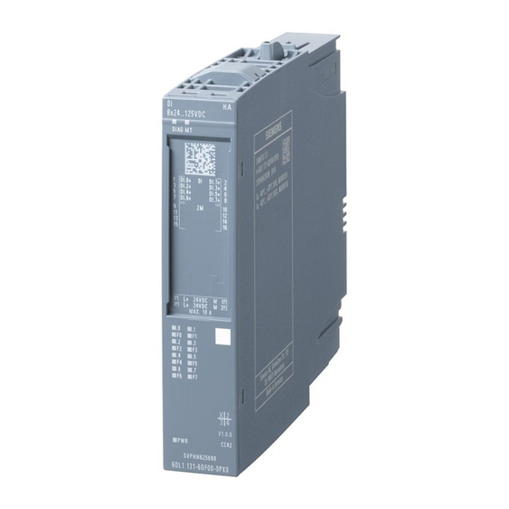
Page 12: Accessories
Product overview 4.2 Accessories Description The I/O module consists of the following components: 8x 24 ..1 25 VD C DI AG M T 1 DI .0 + 3 DI .2+ DI .1+ DI .3 + 5 DI .4 + DI .5 + 7 DI .6 + DI .7+ 1P 1 L+ 24... -
Page 13: Terminal Blocks
Product overview 4.3 Terminal blocks • Reference identification label • Shield connector • Terminal blocks Terminal blocks Definition The terminal blocks provide the process terminals (push-in terminals) for components to be connected such as devices. Description The following terminal blocks are available for the I/O module: Article No. - Page 14 Product overview 4.3 Terminal blocks DI 8x24...125VDC HA Equipment Manual, 10/2021, A5E39288633-AD...
-
Page 15: Terminal
Terminal Terminal assignment Definition The pin assignment provides you with information on the arrangement and marking of the connections when wiring a plug-in connector. DI 8x24...125VDC HA Equipment Manual, 10/2021, A5E39288633-AD... -
Page 16: Terminal Assignment Of The Di 8×24
Terminal 5.1 Terminal assignment Description The pin assignment is made as follows: Table 5-1 Terminal assignment of the DI 8×24...125VDC HA Terminal Assignment Terminal Assignment Explanations : Input signal, channel n 2M: Signal voltage 1P1: Supply voltage L+ of the voltage bus 1P 2P1: Supply voltage L+ of the voltage bus 2P 1P2: Ground reference of the voltage bus 1P 2P2: Ground reference of the voltage bus 2P... -
Page 17: Sample Connection Scheme For A Digital 2-Wire Sensor
Terminal 5.3 Schematic circuit diagram Sample connection scheme for a digital 2-wire sensor Example Schematic circuit diagram Definition A block diagram contains the schematic representation of individual function blocks. DI 8x24...125VDC HA Equipment Manual, 10/2021, A5E39288633-AD... - Page 18 Terminal 5.3 Schematic circuit diagram Description DIAG Status Channel 0...7 Status Diagnostics Error channel 0 Error channel 7 Voltage 24 V DC 3.3 V monitoring Reverse polarity protection A resistor must be connected to the encoder contacts in order to perform wire-break detection. The resistor used is dependent on the nominal input voltage of the module.
-
Page 19: Parameters
Parameters Parameter types Definition You define and thereby influence the functions supported by the module operation of the I/O module via the parameter types. Module/channel parameters Definition Module/channel parameters are specific parameters whose configuration can affect the entire module or channel. Description The following module/channel parameters are available: Note... -
Page 20: Parameter Reassignment
Parameters 6.4 Explanation of the module/channel parameters Parameter Value range Default Parameter re‐ Efficiency range assignment in Input delay (Page 21) 3.2 ms Channel • None • 0.05 ms • 0.1 ms • 0.4 ms • 0.8 ms • 1.6 ms •... -
Page 21: Diagnostics, Missing Supply Voltage L
Parameters 6.4 Explanation of the module/channel parameters 6.4.2 Diagnostics, Missing supply voltage L+ Definition Enabling of the diagnostics for missing or insufficient supply voltage L+. 6.4.3 Diagnostics, Wire break Definition With activated wire break checking, the diagnostics are enabled when the line is from the actuator is interrupted. -
Page 22: Potential Group
Parameters 6.4 Explanation of the module/channel parameters 6.4.8 Potential group Definition A potential group consists of a group of directly adjacent I/O modules within an ET 200SP HA station that are supplied via a common supply voltage. Description A potential group is built up from left to right by using terminal blocks. A new potential group starts on the left side with a light gray terminal block, via which the supply voltage for the potential group is fed in. -
Page 23: Displays And Interrupts
Displays and interrupts Status and error displays Definition The LED displays are used as status and error indicators. Diagnostic messages and maintenance events and their possible causes or remedial measures are described in the Diagnostic messages and Maintenance events. Diagnostics alarms (Page 37) Description The following figure identifies the LED displays of the I/O module. -
Page 24: Leds
Displays and interrupts 7.2 LEDs LEDs 7.2.1 DIAG LED Definition The DIAG LED provides you diagnostic information. Description The diagnostic display of the DIAG LED is as follows: DIAG LED Meaning The power supply of the ET 200SP HA is disrupted or switched off. Module is not configured. -
Page 25: Channel Status / Fault Leds
Displays and interrupts 7.3 Interrupts 7.2.3 Channel status / fault LEDs Definition The channel status and channel fault LEDs provide you information about the status and faults of the channels. Description The channel status and channel fault LEDs indicate the following: Channel Channel Meaning... - Page 26 Displays and interrupts 7.3 Interrupts Description The I/O module supports diagnostic interrupts. The I/O module generates a diagnostic interrupt for the following events: • Wire break • Supply voltage missing • Module is faulty • Channel/component temporarily unavailable • Hardware interrupt lost •...
-
Page 27: Technical Specifications
Technical specifications Technical data of DI 8×24...125VDC HA Article number 6DL1131-6DF00-0PK0 General information Product type designation DI 8x24 ... 125 V DC HA Firmware version V1.0 • FW update possible Usable terminal block TB type K0 Color code for module-specific color identifica‐ CC42 tion plate Product function... - Page 28 Technical specifications Article number 6DL1131-6DF00-0PK0 Input characteristic curve in accordance with IEC 61131, type 3 Time stamping Yes; Resolution 10 ms Time stamp (with precision of 1 ms) Yes; Resolution 1ms Input voltage -125 ... +5 V • for signal "0" +11 ...
- Page 29 Technical specifications Article number 6DL1131-6DF00-0PK0 Weights Weight, approx. 165 g DI 8x24...125VDC HA Equipment Manual, 10/2021, A5E39288633-AD...
- Page 30 Technical specifications Article number 6DL1131-6DF00-0EK0 General information Firmware version V1.0 • FW update possible Usable terminal block TB type K0 Color code for module-specific color identifica‐ CC42 tion plate Engineering with V8.0 • SPPA-T3000 can be configured/integrated from version Operating mode •...
- Page 31 Technical specifications Article number 6DL1131-6DF00-0EK0 • 2-wire sensor 1.5 mA – permissible quiescent current (2-wire sensor), max. Interrupts/diagnostics/status information Diagnoses • Diagnostic information readable • Monitoring the supply voltage • Group error Diagnostics indication LED • MAINT LED Yes; Yellow LED Yes;...
- Page 32 Technical specifications Minimum pulse length In order for a pulse or an edge transition to be reliably detected by the I/O module, the signal status must be active for at least for the time period of the minimum pulse length. The minimum pulse length is greater than the input delay and greater than the cycle time.
-
Page 33: Parameters, Diagnostics Messages And Address Space
Parameters, diagnostics messages and address space Parameter assignment Parameter assignment in the user program You can reconfigure individual channels of the module in RUN without this having an effect on the other channels. Changing parameters in RUN The "WRREC" instruction is used to transfer the parameters to the module using data record 128. Output parameter STATUS If errors occur when transferring parameters with the "WRREC"... -
Page 34: Parameter Assignment And Structure Of The Module/Channel Parameters
Parameters, diagnostics messages and address space A.2 Parameter assignment and structure of the module/channel parameters Error_ Error_ Cause Solution Code_ Code_ 0xE1 0x01 Reserved bit set Check and correct the parameters 0xE1 0x02 Invalid diagnostics enable bit set for operating mode 0xE1 0x03 Invalid hardware interrupt enable bit set for operating... - Page 35 Parameters, diagnostics messages and address space A.2 Parameter assignment and structure of the module/channel parameters DI 8x24...125VDC HA Equipment Manual, 10/2021, A5E39288633-AD...
- Page 36 Parameters, diagnostics messages and address space A.2 Parameter assignment and structure of the module/channel parameters Header information and module parameters The following figure shows the structure of the header information and module parameters. Channel parameters Every channel parameter block contains the channel parameters for the digital input (2 bytes). The following figure shows the configuration of the channel parameters for channels 0 to 7.
-
Page 37: Diagnostics Alarms
Parameters, diagnostics messages and address space A.3 Diagnostics alarms All unused bits and the bits or bytes marked as "reserved" must be set to zero. You activate a channel parameter by setting the corresponding bit to "1" or the corresponding value. -
Page 38: Maintenance Events
Parameters, diagnostics messages and address space A.4 Maintenance events switched off. For diagnostic messages which refer to individual channels, only the corresponding digital input is affected. Diagnostics Error Assignment Meaning Solution message code Wire break Digital input Impedance of encoder circuitry is too Use a different encoder type or high modify the wiring, for example,... -
Page 39: Hardware Interrupts
Parameters, diagnostics messages and address space A.5 Hardware interrupts Maintenance messages do not have a direct influence on the functions of the module or digital inputs. Maintenance Fault code Assignment Meaning / Cause Solution message Retentive memo‐ Module Fault detected in the data block on the Replace carrier module ry in carrier mod‐... -
Page 40: Address Space
Parameters, diagnostics messages and address space A.7 Address space of the time stamping (accuracy 1 ms) Address space Abbreviations • "IB" stands for input byte, that is, the module start address in the input area • "DI" stands for digital input •... - Page 41 Parameters, diagnostics messages and address space A.7 Address space of the time stamping (accuracy 1 ms) Digital mode with time stamping (accuracy 1 ms) The following tables show the assignment of the address space of the DI 8x24...125VDC HA module in digital mode with time stamping (accuracy 1 ms). Address space The following figure shows the mapping of the address space of the DI 8x24...125VDC HA with time stamping (accuracy 1 ms).
- Page 42 Parameters, diagnostics messages and address space A.7 Address space of the time stamping (accuracy 1 ms) DI 8x24...125VDC HA Equipment Manual, 10/2021, A5E39288633-AD...
Need help?
Do you have a question about the SIMATIC 6DL1131-6DF00-0PK0 and is the answer not in the manual?
Questions and answers