
Related Manuals for Siemens XC10 Series


Summary of Contents for Siemens XC10 Series
- Page 1 XC10 Extinguishing control unit XC1001-A / XC1005-A / XC1003-A Installation Commissioning Maintenance MP2.1 Building Technologies Fire Safety & Security Products...
- Page 2 Sous réserve de modifications techniques et de la disponibilité. © 2010 Copyright by Siemens Switzerland Ltd Wir behalten uns alle Rechte an diesem Dokument und an dem in ihm dargestellten Gegenstand vor. Der Empfänger anerkennt diese Rechte und wird dieses Dokument nicht ohne unsere vorgängige schriftliche Ermächtigung ganz oder teilweise Dritten zugänglich machen oder außerhalb des Zweckes verwenden, zu dem es ihm übergeben worden ist.
-
Page 3: Table Of Contents
About this document ................7 Safety instructions..................9 Danger levels ....................9 Safety instructions..................9 Standards and directives complied with..........10 Standards....................11 Overview ....................12 XC1001-A....................12 XC1005-A....................13 XC1003-A....................14 FCP1004-E .....................15 XCM1002 ....................16 User interface..................18 Features ....................21 Installation .....................22 XC1001-A / XC1005-A ................22 XC1003-A....................24 User interface labels ................28 Connections ..................29 Mains.......................29 Batteries ....................29... - Page 4 FCA1007 – Key switch................46 FDCI222 / FDCIO222 – Input/output interfaces........46 Remote transmitter..................46 Operating access levels ...............47 10.1 Operating access level 1.................47 10.2 Operating access level 2.................47 10.3 Operating access level 3A ..............47 10.4 Operating access level 3B ..............47 Extinguishing process diagrams ............48 Programming ..................49 12.1 Before starting ..................49...
- Page 5 17.1 Anticipated Silence Sounders ..............72 17.2 Anticipated Reset ..................72 Maintenance PC ..................73 Components and spare parts ..............74 Building Technologies A6V10257473_b_en_--.doc Fire Safety & Security Products 01.2010...
-
Page 7: About This Document
About this document About this document Purpose of the document This document describes the installation, the commissioning and the maintenance of the XC10xx-A equipment. It provides an overview of the structure and functions of the system as a whole as well as of the individual devices. While following the instructions, a reliable operation is assured. - Page 8 About this document Revision history Document no. Edition date Brief description A6V10257473_a_en_-- 11/2009 First edition MP2.1 A6V10257473_b_en_-- 01/2010 Corrections after field tests: - Chap. 3: Standards / 4.19 monitoring the status of components (spelling mistake) - Chap.4: fig 4 updated - Chap.
-
Page 9: Safety Instructions
Safety instructions Safety instructions Danger levels The following pictograms indicate the possible danger levels, their severity and consequences. Imminent danger! DANGER Serious injuries or death. Potentially dangerous situation WARNING Serious injuries or death. Potentially dangerous situation CAUTION Light injuries or material damage. Important information requiring special attention. -
Page 10: Standards And Directives Complied With
Personal injury or damage to property caused by poor maintenance or lack of maintenance Standards and directives complied with A list of the standards and directives complied with is available at your Siemens contact partner. Building Technologies A6V10257473_b_en_--.doc Fire Safety &... -
Page 11: Standards
Standards Standards In addition to the requirements of EN12094-1 and EN54-2, the XC10xx-A control panel complies with the following optional functions: EN 12094-1 Clause Description 4.17 Delay of extinguishing signal 4.18 Signal representing the flow of extinguishing agent 4.19 Monitoring the status of components 4.20 Emergency hold device 4.21... -
Page 12: Overview
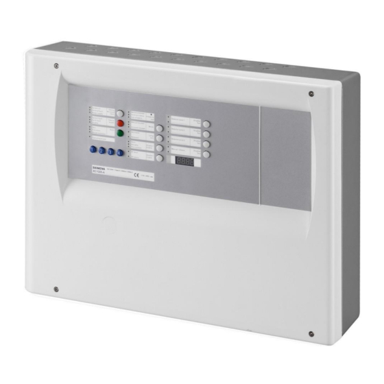
Overview Overview The equipment is declined in 3 versions: Wall mounting cabinet: XC1001-A / XC1005-A 19” rack cabinet: XC1003-A XC1001-A Fig. 1 XC1001-A FCP1004-E power supply unit with charger XCM1002 mainboard 4.5 A/h batteries DIN rail for accessory mounting (Z3B171 relay module) Building Technologies A6V10257473_b_en_--.doc Fire Safety &... -
Page 13: Xc1005-A
Overview XC1005-A Fig. 2 XC1005-A FCP1004-E power supply unit with charger XCM1002 mainboard 17 A/h batteries DIN rail for accessory mounting (Z3B171 relay module) FDCI / FDCIO222 module for the connection to a fire detection system (option) Building Technologies A6V10257473_b_en_--.doc Fire Safety &... -
Page 14: Xc1003-A
Overview XC1003-A Fig. 3 XC1003-A FCP1004-E power supply unit with charger XCM1002 mainboard Removable mainboard holder 4.5 A/h or 7.2 A/h batteries DIN rail for accessory mounting (Z3B171 relay module, XCA1030 multi-sector modules, etc.) FDCI / FDCIO222 module for the connection to a fire detection system (option) Building Technologies A6V10257473_b_en_--.doc... -
Page 15: Fcp1004-E
Overview FCP1004-E Fig. 4 FCP1004-E power supply unit Mark Function Remarks Mains voltage setting Shunt ON = 115V , shunt OFF = 230V Mains terminal block Mains fuse 4A / 250V System start without mains power Shunt the 2 terminals with a jumper and remove after system start Temperature sensor for battery charging voltage compensation Do not cover... -
Page 16: Xcm1002
Overview XCM1002 Fig. 5 XCM1002 board Setting elements Internal buzzer Enable/Disable Jumper up (factory setting) : buzzer enabled Jumper down : buzzer disabled (only for servicing) Type of power supply Jumper up (factory setting) : FCP1004-E Jumper down : do not use (for further use of external power supply) Operating access Level 2 Jumper on the right (factory setting) : Level 2 access using code Jumper on the left : Level 2 access permanent... - Page 17 Overview PCB terminal blocks Plug-in block 6 points 1-2 (–) / 5-6 (+) 24V power supply (1.5 mm max.) 3-4 (+) Power supply monitoring Plug-in block 4 points 1 (+) / 2 (–) Monitored output 5 (2.5 mm max.) 3 (+) / 4 (–) 24V use output Plug-in block 4 points 1 (+) / 2 (–)
-
Page 18: User Interface
Overview User interface All display and control elements, except 4-digit display for XC1001-A and XC1003-A versions, are accessible to the user: Led 1 to 32 indicators for operating condition, Keys 1 to 15 allowing : operating access operation (reset, off, test, etc) system test user functions programming 4-digit display showing:... - Page 19 Overview Indicators State Description N° Color Yellow Fixed Manual release is blocked or being tested – Yellow Fixed Standard = not used – Alternative = automatic and manual release granted (UK) – Yellow Fixed Automatic release is blocked – – At least one detection zone which starts the extinguishing is off or being tested Fixed –...
- Page 20 Overview Keys Description 1 … 4 Operating access code input (level 2, programming, system test, etc.) Silence / Restart sounders by successive pressing: 1st pressing: silence sounders – 2nd pressing: restart sounders – – 3rd pressing: silence sounders – Operating access level required for this operation = level 2 (silence sounders is not possible during pre-warning time) Silence buzzer Operating access level required for this operation = level 1 or 2 or 2 only (*) 1) Reset of the system.
-
Page 21: Features
Type / number of detectors Collective / 32 max. (according to detector type) Detection lines Compatible detectors Siemens (Algorex, Sinteso, Synova) End of line element (EOL) Transzorb 18 V (P6KE18CA) Standby condition voltage / current 17.1 … 19.3 V (fixed by EOL) / 11 mA max. -
Page 22: Installation
Installation Installation Generally, the XC10 must be easily accessible and installed: outside the protected area protected from mechanical shocks and bad weather XC1001-A / XC1005-A The XC10 must be installed on a fixed and stable support, with a height ranging between 1.60 m and 1.70 m (eliminate the irregularities from the mounting surface ≥... - Page 23 Installation 3 (insert in slot 4) 12 V – 12 Ah batteries 12 V – 17 Ah batteries FCA1014 battery holder (option) Slot for battery holder Fig. 8 XC1005-A, battery installation Building Technologies A6V10257473_b_en_--.doc Fire Safety & Security Products 01.2010...
-
Page 24: Xc1003-A
Installation XC1003-A Fix the XC1003-A into a 19'' housing cabinet with a protection rating IP ≥ 30. Cover Cover ZONE EXTINCTION : EN 12 09 4 -1 C la sse A 1 11 6 - C PD – xxx XC1003-A E N5 4- 4 / E N5 4 -2 …………………………………………………….. - Page 25 Installation XC1003-A, mounting adaptation The 19” rack is symmetrical. This allows, with some mounting/unmounting operations, to adapt it to various configurations (2 racks minimum are necessary). Remove parts 1, 2, 3 & 4 from rack A Remove parts 5 & 6 from rack B Reassemble parts 5 &...
- Page 26 Installation XC1003-A, commissioning / connection / maintenance The removable board holder (1) can be positioned, after screw unmounting (3), as indicated below to reach the DIN rail (2). Fig. 11 XC1003-A, removable stand in “Commissioning” position Building Technologies A6V10257473_b_en_--.doc Fire Safety & Security Products 01.2010...
- Page 27 Installation XC1003-A, batteries installation 4.5 Ah batteries: 1. Remove the holder (1) 2. Install the batteries (3) as shown below 3. Remount the holder (1) 7.2 Ah batteries: 1. Remove the parts (1) and (2) 2. Install the batteries (4) as shown below Fig.
-
Page 28: User Interface Labels
Installation User interface labels Insert the labels following the instructions on the board provided with the equipment. XC1001-A Pos. 1 Pos. 3 Pos. 7 XC1003-A XC1005-A Stripe EN A5Q00034729A-03 System ON Silence Detector Zone 1 Disable Detector Zone 1 Disable Re-sound Test Test... -
Page 29: Connections
Connections Connections The installation must be realised by qualified personnel and in conformity with the applicable national electric standard. Mains Connection with the mains must be established through an external circuit breaker (bipolar circuit breaker 1 A). 1. Make sure that the mains voltage is switched off 2. -
Page 30: Fire Detectors/Manual Release Control Buttons
Connections Fire detectors/Manual release control buttons Four monitored inputs are available on the X10 terminal block for the connection of fire detectors or alarm contact (i.e. contact from FDCIO222) and electrical manual triggering devices (DM1103-L) Detection zones 1 to 3 operation is defined at programming steps 52 to 55 (see paragraph 12.14) Extinguishing manual release control operation does not require programming. -
Page 31: Monitored Inputs
Connections Monitored inputs Four monitored inputs are available on X9 terminal block for the connection of various devices. Operation is defined at programming steps 28 to 31 (see paragraph 12.9). Technical data common to the 4 inputs EOL: 3.3 k resistance connected at the end of the line Line resistance max.: 80 7.4.1 Monitored input 1... -
Page 32: Monitored Input 3
Connections 7.4.3 Monitored input 3 This input can be used for several purposes. Operation is defined at programming step 30. Fig. 18 XC10xx-A, monitored input 3 connection Mechanical blocking device Extinguishing remote activation Automatic blocked / Manual blocked / Automatic and manual blocked Emergency abort 7.4.4 Monitored input 4... -
Page 33: Control Inputs
Connections Control inputs Four control inputs, including three programmable (2 to 4), are available on X27 terminal block to receive controls or information via relay contacts. Operation is defined at programming steps 48 to 51 (see paragraph 12.13). Fig. 20 XC10xx-A, control inputs connection These inputs shall not be activated by an external +24 V –... -
Page 34: Monitored Control Outputs
Connections Monitored control outputs Five monitored control outputs are available on terminal blocks X7, X6 and X5 for the connection of various devices. Technical data for control outputs 1 to 3 activation by reverse polarity (polarities indicated are “activated” polarities, according to connected device, a diode can be necessary) line monitoring: 3.3 k resistance connected at the end of the line protection: 1 AT fuse (F4 / F5 / F6) -
Page 35: Monitored Control Output 1
Connections 7.6.1 Monitored control output 1 This output is exclusively reserved for the connection of the Sounders. Operation is defined at programming step 05 (see paragraph 12.4). Fig. 21 XC10xx-A, monitored control output 1 connection 7.6.2 Monitored control output 2 This output can be used for several purposes. -
Page 36: Monitored Control Output 4
Pyrotechnic actuators 1 to 10 actuators maximum, connected in series, can be connected. The table below indicates max. line lengths, in meters, according to cable section for the Siemens Monopist pyrotechnic actuator : MONOPIST / code A6E60200462 1.5 mm 1067 2.5 mm... -
Page 37: Monitored Control Output 5
Connections 7.6.5 Monitored control output 5 This output can be used for several purposes. Operation is defined at programming steps 03 and 14 (see paragraphs 12.3 and 12.6). Fig. 25 XC10xx-A, monitored control output 5 connection Actuators (electromagnetic or pyrotechnic) Fire control(s): signal triggering to equipment outside the system according to EN12094-1 option with requirements 4.26 Warning panel(s) «... -
Page 38: Programmable Outputs
Connections Programmable outputs An output, among those described in this chapter, must obligatorily be programmed to transmit the following information’s: « Emission » (in all cases) « Mechanical blocking » (1) « Emergency hold/abort » (1) « Automatic blocked » (1) When these options with requirements are used. -
Page 39: Relay Outputs
Connections 7.7.2 Relay outputs Five potential-free contacts, including 4 programmable (1, 2, 4 and 5), are available on X11 terminal block to forward the event states to a remote transmission device or to a fire detection system. Operation is defined at programming steps 15 to 19 (see paragraph 12.7). -
Page 40: Multi-Sector Installation
Multi-sector installation Multi-sector installation Multi-sector extinguishing systems are capable of protecting several flooding zones. The basic setup consists of one common cylinder bank. To this cylinder bank, a piping network is connected to every flooding zone by means of selector valves. -
Page 41: Xca1031 Common Module Description
Multi-sector installation Flooding zone 1 Flooding zone 2 Flooding zone 3 Control Sector 1 cylinder Sector 2 Sector 3 Loss of agent Actuator XCA1031 Inter-blocking Communication (RS485) XCA1030 XCM1002 XCA1030 XCM1002 XCA1030 XCM1002 XC1003-A / Sector 1 XC1003-A / Sector 2 XC1003-A / Sector 3 Fig. -
Page 42: Xca1030 Individual Module Description
Multi-sector installation electrical faults (break or short circuit) are forwarded, via output D, to all the extinguishing control panels in order to display « Actuators fault » Output D: forwards to all extinguishing control panels the following information: loss of agent short circuit or break of “Loss of agent”... -
Page 43: Multiple Flooding Zones Modules Overview
Multi-sector installation Multiple flooding zones modules overview Fig. 29 XCA1031, multiple flooding zones common module Mark Terminals Function 1 (+) / 2 (–) 24 V power supply input N° 1 3 (+) / 4 (–) 24 V power supply input N° 2 1 (–) / 2 (+) Extinguishing agent monitoring 3 (–) / 4 (+) -
Page 44: Multiple Flooding Zones Modules Assembly And Connection
Multi-sector installation Multiple flooding zones modules assembly and connection Multiple flooding zones modules are mounted on a DIN rail: XCA1031 : in the 19" cabinet where XC1003-A control units are installed XCA1030 : in each XC1003-A (see Fig. 3) The drawing below shows a connection example between XCA1030 modules and the XCA1031 for a 3 flooding zones installation. -
Page 45: Multisector Modules Technical Specification
Multi-sector installation Multi-sector modules technical specification XCA1031: Actuator output 1 and 2: device can be either electromagnetic or pyrotechnic actuator activation by reverse polarity (polarities indicated are “activated” polarities, according to connected device, a diode can be necessary) line monitoring: 3.3 k resistance connected at the end of the line protection: 1 AF fuse (F1 / F2) cable type: 2 x 2.5mm max. -
Page 46: Accessories
Accessories Accessories FCA1007 – Key switch This device, only usable with XC1001-A and XC1005-A control panel, is connected to the terminal block X8 of XCM1002 mainboard (see paragraph 4.5) and allows operating access level 2 access per key rather than by code: the use must be defined by programming (see paragraph 12.15) mounting instructions are delivered with the product FDCI222 / FDCIO222 –... -
Page 47: Operating Access Levels
Operating access levels Operating access levels XC10xx-A equipment operation is organised in several operating access levels. 10.1 Operating access level 1 This level gives access to: silence buzzer (see programming options in step 56) led test fault detailed display alarm counter display (XC1005-A only) 10.2 Operating access level 2 This operating access level gives access, after code input on keyboard (4 2 3 3 by... -
Page 48: Extinguishing Process Diagrams
Extinguishing process diagrams Extinguishing process diagrams The following diagrams show the execution of an extinguishing process initiated by an automatic activation, a manual release and a mechanical release on the cylinders (optional). Fig. 33 Extinguishing process initiated by automatic detectors Fig. -
Page 49: Programming
Programming Programming 12.1 Before starting Some of the programming options are entitled « Processing as ». This means that an output, programmed with this option, will function in the same way: Processing as : Description RT-alarm Output can be disabled via key 11 (“Disable RT-Alarm”) Output line fault is reported on “RT-alarm”... -
Page 50: Presettings
Programming 3. Press and hold down the key « Silence buzzer » (6) then enter the digit code 1 4 2 4 2 3 2 1 on the keyboard to enter programming: “Disable” LED(6) lights up (fixed), « Test » (7), « Fire alarm » (8) and «... - Page 51 Programming Presettings and corresponding options (FR) (DK) (CH) (SE) (CZ) (BE) (NL) (FI) (SP) (factory) Building Technologies A6V10257473_b_en_--.doc Fire Safety & Security Products 01.2010...
-
Page 52: Steps 01 To 04 - Time Duration Settings
Programming 12.3 Steps 01 to 04 – Time duration settings Description Step Option Pre-discharged warning time The Pre-discharged warning time sets the countdown duration before the actuator extinguishing release triggering. During this time, the reset function is not possible. Adjustable from 0 to 60 seconds by step of 5 seconds Default : 30 s 0 second 5 seconds... -
Page 53: Step 05 - Sounders
Programming 12.4 Step 05 - Sounders Description Step Option Sounders: program the pattern Fire alarm Activated Emergency hold/abort Released Continuous Pulsated fast Pulsated slow Pulsated fast Pulsated slow Pulsated fast Pulsated slow Continuous Pulsated fast Pulsated long Pulsated fast Continuous Pulsated slow Continuous Pulsated slow... -
Page 54: Steps 10 To 14 - Monitored Outputs 1 To 5
Programming 12.6 Steps 10 to 14 - Monitored outputs 1 to 5 Description Step Option Monitored output 1 : select the operation Processing as “Sounder” Active until “Silence/Re-sound” or “Reset” via non-monitored control input 1 Monitored output 2 : select the operation Processing as “RT-alarm”... -
Page 55: Steps 15 To 19 - Relay Contact 1 To 5
Programming 12.7 Steps 15 to 19 - Relay contact 1 to 5 Description Step Option Relay output 1 : select the function Processing as “Fire control A” Processing as “Fire control B” Processing as “Fire control C” Active in state ”Fire alarm” Active in state ”Activated”... -
Page 56: Steps 20 To 27 - Driver Outputs 1 To 8
Programming 12.8 Steps 20 to 27 – Driver outputs 1 to 8 Description Step Option Driver output 1 : select the function Processing as “Fire control A” Processing as “Fire control B” Processing as “Fire control C” Active in state ”Fire alarm” Active in state ”Activated”... -
Page 57: Steps 28 To 31 - Monitored Inputs 1 To 4
Programming 12.9 Steps 28 to 31 - Monitored inputs 1 to 4 Description Step Option Monitored input 1 : released contact Contact (1.2 k ) normally closed when there is no gas in piping Contact (1.2 k ) normally opened when there is no gas in piping No contact ("Released"... -
Page 58: 12.10 Steps 32 To 38 - Reset
Programming 12.10 Steps 32 to 38 - Reset Description Step Option Reset: zones 1 and 2 operation Alarm < 15 seconds after reset = "Alarm" Alarm < 15 seconds after reset = "Fault" Reset: zone 3 operation Alarm < 15 seconds after reset = "Alarm" Alarm <... -
Page 59: 12.12 Steps 44 To 47 - Faults
Programming "Released" led flashes fast + "Fault" "Released" led is not activated + "Fault" "Released" led is not activated The corresponding relay contacts and/or driver outputs are activated The corresponding relay contacts and/or driver outputs are not enabled Loss of agent: select the display during flooding time Indicated after "Released"... -
Page 60: 12.14 Steps 52 To 55 - Detection Zones
Programming Same options as non monitored control input 2 – default = 12 State is maintained as long as a potential +24V is applied Pulse control (0.2 s minimum) Control must be possible through a level 2 access device only 12.14 Steps 52 to 55 - Detection zones Description Step... -
Page 61: 12.16 Step 58 - Multi-Sector
Programming 12.16 Step 58 – Multi-sector Description Step Option Multi-sector operation The panel is not part of a multi-sector installation The panel is part of a multi-sector installation, including inter-blocking (see EN12094-1 option 4.29) / Valid only for XC1003-A The panel is part of a multi-sector installation, without inter-blocking / Valid only for XC1003-A 12.17 Step 59 - Detectors Description Step... -
Page 62: Commissioning
Commissioning Commissioning Before commissioning, ensure that: the control unit is correctly mounted on a fixed support all detector bases are correctly connected all monitored lines are correctly connected and equipped with respective EOL all accessory or optional parts are present FCP1004-E power supply setting correspond to the mains voltage mains voltage is available batteries are installed, but not connected yet... -
Page 63: System Test
Commissioning 13.3 System test 1. check the extinguishing process by automatic and manual activation 2. check display of "Released" condition 3. check the pre-warning time 4. check sounders and warning panels operation 5. check RT-Alarm and RT-Fault 6. check fire controls operation 7. -
Page 64: Maintenance
Maintenance Maintenance 14.1 Preventive maintenance Tasks to be carried out weekly: check all panel indications and press "Led test" Tasks to be carried out annually: check automatic activation check manual activation check released condition by activation of the discharged contact check emergency hold/abort devices check mechanical blocking device check loss of agent indication... -
Page 65: Detailed Fault Display
Maintenance 14.2 Detailed fault display Press simultaneously keys “1” and “3” of the numeric keypad: Faults appear for 5 seconds according to the table below OL: Open Line SC: Short Circuit Designation State Significance N° Color Yellow Fault Fixed Multi-sector function: individual module (XCA1030) disconnected Slow Multi-sector function: RS485 bus (OL / SC / communication fault) Yellow... - Page 66 Maintenance Designation State Significance N° Color Yellow Actuators Fixed Monitored output 2 Slow Yellow Fire controls Fixed Monitored output 3 Slow Yellow RT-Fault Fixed Monitored output 4 Slow Fast Calibration error Yellow RT-Alarm Fixed Monitored output 5 Slow Fast Calibration error Zone 1 Fixed Alarm <...
-
Page 67: Test Functions
Test functions Test functions Generally, test functions described in this chapter are only possible when the equipment is in standby condition (=no alarm). If an alarm occurs, the test ends immediately. 15.1 Lamp test Press the « Lamp test » (9) key and check that: all leds light up internal buzzer sounds all segments of the display light up and software version is displayed (requires... -
Page 68: Rt-Alarm Test
Test functions 15.4 RT-alarm test 1. Enable operating access level 2 2. Press and hold down key « 3 » on numeric keypad then press the « Silence / Re-sound sounder » key (5): RT-alarm outputs are enabled for 30 seconds «... -
Page 69: Individual Output Test
Test functions 15.7 Individual output test All the outputs, except those programmed as actuators, can be tested individually: The individual test of the outputs, once enabled, automatically ends after 1 mn if no action is carried out for this period The outputs can be tested only one by one (duration = 3 mn max.) During test phase: Alarms and faults are not indicated... -
Page 70: Zone Test
Test functions 15.8 Zone test Zone test makes it possible to check each connected detector. Procedure 1. Enable operating access level 2 2. Press 2 times the key "Disable/Test/Enable" (12 to 14) corresponding to the zone to be tested: The yellow led of the zone (26, 28, 30) and the yellow led "Test" (7) flash slowly The yellow led "Disable"... -
Page 71: Advanced Functions
Advanced functions Advanced functions The functions described in this chapter require to remove the front plastic cover for models XC1001-A and XC1003-A. 16.1 Checksum This function makes it possible to check if a programming modification was carried out: 1. Enable operating access level 2 2. -
Page 72: Special Functions
Special functions Special functions The functions described in this chapter must be used only during commissioning and/or maintenance. It is not allowed to use these functions during normal operation. The following access code shall not be delivered to the customer. 17.1 Anticipated Silence Sounders This function makes it possible to stop/start the Sounders during the pre-warning... -
Page 73: Maintenance Pc
Maintenance PC Maintenance PC A PC can be connected with the XC10xx-A equipment to carry out the following operations: Programming upload / download Event memory upload / download Alarm counter reset Recording / printing of programming and event memory Hardware requirement and installation MCL-USB (FDUZ221) adaptor to connect between the PC (USB port) and connector X21 of board XCM1002 (follow installation instructions of the drivers delivered with the product) -
Page 74: Components And Spare Parts
Components and spare parts Components and spare parts Reference Part N° Description Remarks Complete product (*) XC1001-A S54390-C1-A1 XC1001-A Extinguishing panel Standard XC1005-A S54390-C3-A1 XC1005-A Extinguishing panel Comfort XC1003-A S54390-C2-A1 XC1003-A Extinguishing panel Rack Accessories FCA1014 A6E60500069 FCA1014 Battery holder (XC1005-A with 17A/h) XCA1030 S54390-A5-A1 XCA1030 Multi-zone extension module... - Page 76 Siemens Switzerland Ltd Building Technologies Group International Headquarters Fire Safety & Security Products Gubelstrasse 22 CH-6301 Zug Tel. +41 41 724 24 24 Fax +41 41 724 35 22 www.sbt.siemens.com Document no. A6V10257473_b_en_--.doc Manual xx Edition 01.2010 Section x...
Need help?
Do you have a question about the XC10 Series and is the answer not in the manual?
Questions and answers