Table of Contents

Related Manuals for Baldor NextMove ES


Summary of Contents for Baldor NextMove ES
- Page 1 MOTION CONTROL NextMove ES Motion Controller Installation Manual Servo Systems Co. • 115 Main Road • P.O. Box 53 Green Pond Road, Suite #2 • Rockaway, NJ 01/10 07866ree: (800) 922-1103 Fax: (973) 335-1661 • www.servosystems.com...
-
Page 2: Table Of Contents
3.1.2 Installing the NextMove ES card ........ - Page 3 ..........6.1.1 Connecting the NextMove ES to the PC ......
- Page 4 ..........NextMove ES indicators .
- Page 5 8.1.4 Digital inputs (non-isolated) ........8.1.5 Digital inputs (opto-isolated) .
-
Page 6: General Information
This manual is copyrighted and all rights are reserved. This document or attached software may not, in whole or in part, be copied or reproduced in any form without the prior written consent of BALDOR. BALDOR makes no representations or warranties with respect to the contents hereof and specifically disclaims any implied warranties of fitness for any particular purpose. - Page 7 www.baldormotion.com Safety Notice Only qualified personnel should attempt to start-up, program or troubleshoot this equipment. This equipment may be connected to other machines that have rotating parts or parts that are controlled by this equipment. Improper use can cause serious or fatal injury. Precautions Do not touch any circuit board, power device or electrical connection before you first ensure that no high voltage is present at this equipment or other equipment to which it is...
-
Page 8: Introduction
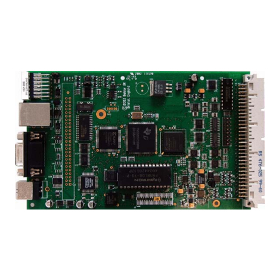
NextMove ES is a high performance multi-axis intelligent controller for servo and stepper motors. NextMove ES features the Mint motion control language. Mint is a structured form of Basic, custom designed for servo or stepper motion control applications. It allows you to get started very quickly with simple motion control programs. - Page 9 Included with NextMove ES is the Baldor Motion Toolkit CD. This contains a number of utilities and useful resources to get the most from you Mint controller. These include: Mint WorkBench This is the user interface for communicating with the NextMove ES. Installing Mint WorkBench will also install firmware for NextMove ES.
-
Page 10: Receiving And Inspection
4. Inspect the NextMove ES for external damage during shipment and report any damage to the carrier that delivered it. 5. If the NextMove ES is to be stored for several weeks before use, be sure that it is stored in a location that conforms to the storage humidity and temperature specifications shown in section 3.1.1. -
Page 11: Units And Abbreviations
www.baldormotion.com 2.3 Units and abbreviations The following units and abbreviations may appear in this manual: ....Volt (also VAC and VDC) ....Watt . -
Page 12: Introduction
The NextMove ES is designed to be mounted in a IEC297 / DIN41494 rack with card frames and guides to support the card. The NextMove ES must be installed in an ambient temperature of 0 °C to 40 °C (32 °F to 104 °F). -
Page 13: Installing The Nextmove Es Card
CAUTION The NextMove ES is designed to be mounted in a IEC297 / DIN41494 rack with card frames and guides to support the card. An additional backplane card is recommended (see section 5). 1. Mount the backplane connector card (optional) at the rear of the rack system. -
Page 14: Other Requirements For Installation
3.1.4 Other requirements for installation The NextMove ES requires +5 V and ±12 V power supplies. The total power requirement (excluding any option cards) is +5 V at 1 A, +12 V at 50 mA and -12 V at 50 mA. If digital outputs are to be used, a supply will be required to drive them - see section 4.4.2. - Page 15 www.baldormotion.com Servo Systems Co. • 115 Main Road • P.O. Box 97 • Montville, NJ, 3-4 Basic Installation MN1928 07045-0097 • (973) 335-1007 • Toll Free: (800) 922-1103 Fax: (973) 335-1661 • www.servosystems.com...
-
Page 16: Input / Output
AOUT ... Analog Output Most external connections to the NextMove ES card are made using an optional backplane card, described in section 5. 4.2 96-pin edge connector c b a The pin assignment for the 96-pin DIN41612 connector is shown in Table 1. -
Page 17: 96-Pin Connector Pin Assignment - Nes002-501 & Nes002-502
www.baldormotion.com 4.2.1 96-pin connector pin assignment - NES002-501 & NES002-502 Pin c +5 VDC +5 VDC +5 VDC +5 VDC +5 VDC +5 VDC DGND DGND DGND DOUT6 DOUT7 OUT COM DOUT3 DOUT4 DOUT5 DOUT0 DOUT1 DOUT2 Encoder 1 CHB+ Encoder 0 CHA+ Encoder 0 CHB+ Encoder 1 CHZ+... -
Page 18: 96-Pin Connector Pin Assignment - Nes002-503
www.baldormotion.com 4.2.2 96-pin connector pin assignment - NES002-503 Pin c +5 VDC +5 VDC +5 VDC +5 VDC +5 VDC +5 VDC DGND DGND DGND DOUT6 DOUT7 OUT COM DOUT3 DOUT4 DOUT5 DOUT0 DOUT1 DOUT2 Encoder 1 CHB+ Encoder 0 CHA+ Encoder 0 CHB+ Encoder 1 CHZ+ Encoder 0 CHZ+... -
Page 19: Analog I/O
4.3 Analog I/O The NextMove ES provides: Two 12-bit resolution analog inputs. Four 12-bit resolution analog outputs. 4.3.1 Analog inputs The analog inputs are available on pins a28 & b28 (AIN0) and a27 & c28 (AIN1). Differential inputs. Voltage range: ±10 V. - Page 20 www.baldormotion.com AIN0+ AIN0+ AIN0 AIN0 AIN0- ADC(0) ADC(0) Differential connection Single ended connection Figure 2 - AIN0 analog input wiring +24 VDC 1.5 kΩ, 0.25 W 1 kΩ, 0.25 W potentiometer AIN0 ADC(0) Figure 3 - Typical input circuit to provide 0-10 V (approx.) input from a 24 V source Servo Systems Co.
-
Page 21: Analog Outputs
AIN0- Shield Connect overall shield at one end only Figure 5 - Analog output - typical connection to a Baldor MicroFlex Servo Systems Co. • 115 Main Road • P.O. Box 97 • Montville, NJ, 4-6 Input / Output MN1928 07045-0097 •... - Page 22 AIN0- Shield Connect overall shield at one end only Figure 6 - Analog output - typical connection to a Baldor FlexDrive , Flex+Drive or MintDrive Servo Systems Co. • 115 Main Road • P.O. Box 97 • Montville, NJ, MN1928 Input / Output 4-7 07045-0097 •...
-
Page 23: Digital I/O
4.4 Digital I/O The NextMove ES provides: 20 general purpose digital inputs. 12 general purpose digital outputs. 4.4.1 Digital inputs The digital inputs are available across a range of pins, as shown in section 4.2.1. All digital inputs have a common specification: 5 V digital inputs with internal pull-up resistors. - Page 24 INX(0) Status- DGND NEC PS2562L-1 Figure 8 - Digital input - typical connections from a Baldor MicroFlex Servo Systems Co. • 115 Main Road • P.O. Box 97 • Montville, NJ, MN1928 Input / Output 4-9 07045-0097 • (973) 335-1007 • Toll Free: (800) 922-1103...
- Page 25 DOUT0 DGND NEC PS2562L-1 User supply Figure 9 - Digital input - typical connections from a Baldor FlexDrive Flex+Drive or MintDrive Servo Systems Co. • 115 Main Road • P.O. Box 97 • Montville, NJ, 4-10 Input / Output MN1928 07045-0097 •...
- Page 26 If the outputs are driving inductive loads such as relays, connect the OUT COM connection to the output’s power supply, as shown in Figure 10. This will connect internal clamp diodes on all outputs. Load supply 24 V NextMove ES Output Load ULN2803 Mint DOUT0...
- Page 27 Note: On model NES002-503, DOUT8 - DOUT11 are not available as general purpose digital outputs. The outputs are used to provide the additional STEP4/5 and DIR4/5 stepper axes outputs (see section 4.5.1). Load supply 24 V NextMove ES Output Load (Relay with diode shown) ULN2003 Mint...
-
Page 28: Error Output - Error Out
4.4.3.2 RELAY keyword If the NextMove ES is connected to an opto-isolated backplane (optional) the output directly controls the relay (see section 5.3.1.1). For this reason, the error output can be controlled by the RELAY keyword. -
Page 29: Other I/O
(model dependent), operating in the range 0 Hz to 500 kHz. Each of the step (pulse) and direction STEP0 STEP3 signals from the NextMove ES is driven by one channel DIR0 DIR3 of a ULN2003 open collector Darlington output device. -
Page 30: Encoder Inputs
The encoder inputs are available on pins a7-a10, b7-b10 and c7-c10. See section 4.2.1. Two incremental encoders may be connected to NextMove ES, each with complementary A, B and Z channel inputs. Each input channel uses a MAX3095 differential line receiver with pull up resistors and terminators. -
Page 31: Usb Port
PC or hub, communication speed will remain at the USB 1.1 specification of the NextMove ES. Ideally, the NextMove ES should be connected directly to a USB port on the host PC. If it is connected to a hub shared by other USB devices, communication could be affected by the activity of the other devices. -
Page 32: Serial Port
Do not attempt to use more than one set of serial connections at the same time. NextMove ES is available with either an RS232 or RS485 serial port (see section 2.2.1). The port is fully ESD protected to IEC 1000-4-2 (15 kV). When the NextMove ES is connected to Mint WorkBench, the Tools, Options menu item can be used to configure the serial port. - Page 33 RTS and CTS lines, these must also be connected. Pins 4 and 6 are linked on the NextMove ES. The maximum recommended cable length is 3 m (10 ft) at 57.6 Kbaud. When using lower baud rates, longer cable lengths may be used up to maximum of 15 m (49 ft) at 9600 baud.
-
Page 34: Multidrop Using Rs485 / Rs422
(slave) devices on the network. The network master can be a controller such as NextMove ES, a host application such as Mint WorkBench (or other custom application), or a programmable logic controller (PLC). RS422 may be used for multi-drop applications as shown in Figure 16. -
Page 35: Connecting Serial Baldor Hmi Operator Panels
Serial Baldor HMI Operator Panels use a 15-pin male D-type connector (marked PLC PORT), but the NextMove ES Serial connector uses a 9-pin male D-type connector. The NextMove ES may be connected with or without hardware handshaking, as shown in Figure 17:... -
Page 36: Can
To determine which firmware is currently installed, start Mint WorkBench and connect to the NextMove ES (see section 6). At the bottom of the Mint WorkBench window, the status bar will show the name of the controller, followed by ‘CANopen’ or ‘Baldor CAN’. If the correct option is not shown, it will be necessary to download alternative firmware by using the Install System File and/or Download Firmware menu items in Mint WorkBench. -
Page 37: Can Wiring
All cables and connectors should have a nominal impedance of 120 Ω. Cables should have a length related resistance of 70 mΩ/m and a nominal line delay of 5 ns/m. A range of suitable CAN cables are available from Baldor, with catalog numbers beginning CBL004-5.. -
Page 38: Canopen
The configuration and management of a CANopen network must be carried out by a single node acting as the network master. This role can be performed by the NextMove ES when it is configured to be the Network Manager node (node ID 1), or by a third party CANopen master device. -
Page 39: Baldor Can
KeypadNode 4 (Baldor part KPD002-505 ) - an operator panel CAN node with 4 x 20 LCD display and 41 key membrane labeled for control of 4 axes (1, 2, 3, 4). A typical Baldor CAN network with a NextMove ES and a Baldor CAN operator panel is shown in Figure 18. - Page 40 Jumpers JP4 and JP5 can be used to configure the node ID and baud rate. Up to 63 Baldor I/O nodes (including no more than 4 operator panels) can be added to the network by the NextMove ES using the Mint NODETYPE keyword. Any network and node related events can then be monitored using the Mint BUS2 event.
-
Page 41: Connection Summary - Minimum System Wiring
As a guide, Figure 21 shows an example of the typical minimum wiring required to allow the NextMove ES and a single axis stepper amplifier to work together. The optional opto-isolating backplane card BPL010-502 is shown. Details of the connector pins are shown in Table 4. - Page 42 www.baldormotion.com Backplane Name of Function Connection on amplifier card signal (Note: connections may be connector labeled differently) USR GND User power supply GND Enable signal ground REL NO Switched relay contact Enable signal input REL COM Common relay connection (linked to USR V+) STEP0- Step signal for axis 0 Step signal for axis 0...
- Page 43 www.baldormotion.com Servo Systems Co. • 115 Main Road • P.O. Box 97 • Montville, NJ, 4-28 Input / Output MN1928 07045-0097 • (973) 335-1007 • Toll Free: (800) 922-1103 Fax: (973) 335-1661 • www.servosystems.com...
-
Page 44: Backplanes
5.1 Introduction This section describes the optional backplane cards available for use with the NextMove ES. These cards all provide standard wiring connections to the NextMove ES, but there are a number of variants available: Baldor part number BPL010-501: Non-isolated backplane. -
Page 45: Bpl010-501 Non-Isolated Backplane
5.2 BPL010-501 non-isolated backplane This backplane provides direct connection to the NextMove ES signals without isolation. The electrical specifications of all signals are therefore the same as described in section 4. In the following sections, the signals AGND, DGND and Shield are listed with nominal corresponding pins on the 96-pin connector, although they are all electrically connected on the backplane. - Page 46 www.baldormotion.com 110 mm (4.43 in) 98 mm (3.86 in) 77.5 mm (3.05 in) 57.5 mm (2.26 in) 37 mm (1.46 in) 16.5 mm (0.65 in) Serial Encoder1 Encoder0 Figure 22 - Backplane BPL010-501 connector layout and dimensions Servo Systems Co. • 53 Green Pond Road, Suite #2 • Rockaway, NJ 07866 MN1928 Backplanes 5-3 07045-0097 •...
-
Page 47: Analog Inputs
www.baldormotion.com 5.2.1 Analog inputs Location X8 Mating connector: Weidmüller Omnimate BL 3.5/10 Pin Name Description 96-pin connector 10 Shield Shield connection 9 DGND Digital ground (NC) 7 ERROR Error output 6 AGND Analog ground 5 AIN1- Analog input AIN1- 4 AIN1+ Analog input AIN1+ 3 AGND Analog ground... -
Page 48: Analog Outputs (Demands)
www.baldormotion.com 5.2.2 Analog outputs (demands) Location X7 Mating connector: Weidmüller Omnimate BL 3.5/12 Pin Name Description 96-pin connector 12 Shield Shield connection 11 AGND Analog ground 10 DEMAND3 Analog output AOUT3 9 Shield Shield connection 8 AGND Analog ground 7 DEMAND2 Analog output AOUT2 6 Shield Shield connection... -
Page 49: Digital Inputs
www.baldormotion.com 5.2.3 Digital inputs 0-7 Location X12 Mating connector: Weidmüller Omnimate BL 3.5/10 Pin Name Description 96-pin connector 10 Shield Shield connection 9 DGND Digital ground 8 DIN7 Digital input DIN7 7 DIN6 Digital input DIN6 6 DIN5 Digital input DIN5 5 DIN4 Digital input DIN4 4 DIN3... -
Page 50: Digital Outputs 0-7
www.baldormotion.com 5.2.5 Digital inputs 16-19 Location X6 Mating connector: Weidmüller Omnimate BL 3.5/5 Pin Name Description 96-pin connector 5 DGND Digital ground 4 DIN19 Digital input DIN19 3 DIN18 Digital input DIN18 2 DIN17 Digital input DIN17 1 DIN16 Digital input DIN16 See section 4.4.1 for electrical specifications of the digital inputs. -
Page 51: Digital Outputs 8-11 (Nes002-501 / Nes002-502 Only)
www.baldormotion.com 5.2.7 Digital outputs 8-11 (NES002-501 / NES002-502 only) Location X5 Mating connector: Weidmüller Omnimate BL 3.5/5 Pin Name Description 96-pin connector 5 DGND Digital ground 4 DOUT11 Digital output DOUT11 3 DOUT10 Digital output DOUT10 2 DOUT9 Digital output DOUT9 1 DOUT8 Digital output DOUT8 See section 4.4.2.2 for electrical specifications of the digital outputs. -
Page 52: Stepper Axes Outputs 0-1
When connecting the outputs to single ended inputs as shown in Figures 25 and 26, do not connect the STEPx- or DIRx- CAUTION outputs to ground; leave them unconnected. NextMove ES Backplane ‘X9’ DS26LS31 STEP0-... -
Page 53: Stepper Axes Outputs 2-3
When connecting the outputs to single ended inputs as shown in Figures 25 and 26, do not connect the STEPx- or DIRx- CAUTION outputs to ground; leave them unconnected. NextMove ES Backplane ‘X10’ DS26LS31 STEP2-... - Page 54 DGND Twisted pairs DS26LS31 connector DIR2+ DIR2- DGND Shield Connect shields at one end only Figure 25 - Stepper output STEP2 - typical connection to a Baldor MicroFlex Backplane FlexDrive / drive amplifier ‘X10’ ‘X9’ DS26LS31 STEP2+ Pulse+ STEP2- Pulse...
-
Page 55: Stepper Axes Outputs 4-5 (Nes002-503 Only)
www.baldormotion.com 5.2.10 Stepper axes outputs 4-5 (NES002-503 only) Location X5 Mating connector: Weidmüller Omnimate BL 3.5/5 Pin Name Description 96-pin connector 5 DGND Digital ground 4 DOUT11 Direction output 5 3 DOUT10 Step (pulse) output 5 2 DOUT9 Direction output 4 1 DOUT8 Step (pulse) output 4 Stepper axes outputs 4-5 are not isolated or driven by the backplane. -
Page 56: Encoder Input 0
www.baldormotion.com 5.2.12 Encoder input 0 Location X3 Encoder0 Mating connector: 9-pin male D-type Name Description 96-pin connector CHA+ Channel A signal CHB+ Channel B signal CHZ+ Index channel signal Shield Shield connection DGND Digital ground CHA- Channel A signal complement CHB- Channel B signal complement CHZ-... -
Page 57: Serial Port
DGND (NC) This serial connector carries the same signals as the serial connector on the NextMove ES control card. Do not use both serial connectors at the same time. * Pins 4 and 6 are linked on the NextMove ES. -
Page 58: Bpl010-502/503 Backplane With Opto-Isolator Card
The female 96-pin connector nearest the edge of the backplane accepts the NextMove ES card. The backplane will not operate without the opto-isolating card. In the following sections, the signals AGND, DGND and Shield are listed with nominal corresponding pins on the 96-pin connector, although they are all electrically connected on the backplane. - Page 59 www.baldormotion.com 130 mm (5.12 in) 113 mm (4.45 in) 92.5 mm (3.64 in) 72.5 mm (2.85 in) 52 mm (2.05 in) 31.5 mm (1.24 in) 11 mm (0.43 in) DOUT8 to 11 are NON -ISOLATED Serial Encoder1 Encoder0 7 mm (0.28 in) Figure 27 - Backplane BPL010-502/503 connector layout and dimensions Servo Systems Co.
-
Page 60: Analog Inputs
Analog input AIN0- AIN0+ Analog input AIN0+ The analog inputs on the backplane are connected directly to the NextMove ES and do not pass through any circuitry on the opto-isolator card. See section 4.3.1 for electrical specifications of the analog inputs. - Page 61 When an error occurs, the relay is de-energized, and REL COM is connected to REL NC. It is important that the NextMove ES jumper settings are correct to allow it to control the backplane relay. JP4 and JP5 must be fitted. Jumper JP3 must be removed.
-
Page 62: Analog Outputs (Demands)
1 DEMAND0 Demand 0 output (AOUT0) The outputs on the backplane are connected directly to the NextMove ES and do not pass through any circuitry on the opto-isolator card. See section 4.3.2 for electrical specifications and how to connect an output to a typical drive amplifier. -
Page 63: Digital Inputs 8-15
5.3.3 Digital inputs 0-7 Location Mating connector: Weidmüller Omnimate BL 3.5/10 Name Description NextMove ES 96-pin connector Shield Shield connection USR GND Customer power supply ground DIN7 Digital input DIN7 DIN6 Digital input DIN6 DIN5 Digital input DIN5 DIN4... -
Page 64: Digital Inputs 16-19
5.3.4 Digital inputs 8-15 Location Mating connector: Weidmüller Omnimate BL 3.5/10 Name Description NextMove ES 96-pin connector Shield Shield connection USR GND Customer power supply ground DIN15 Digital input DIN15 DIN14 Digital input DIN14 DIN13 Digital input DIN13 DIN12... - Page 65 5 mA in the input circuit. To ensure that an input becomes inactive, the current must be less than 1 mA. The internal pull-up resistor on the NextMove ES allows the input to be left floating when inactive or not being used.
- Page 66 24 V DIN16 Status+ Status- NEC PS2562L-1 USR GND connector TLP521-4 User supply Figure 32 - Digital input - typical connections from a Baldor MicroFlex User FlexDrive / equipment output Backplane & opto-isolator card ‘X1’ ‘X6’ supply 24 V DIN16...
- Page 67 The user power supply connection USR V+ is common to all inputs. To activate an input it must be grounded to the 0 V side of the user power supply (USR GND). The internal pull-up resistor on the NextMove ES allows the input to be left floating when inactive or not being used.
- Page 68 DOUT0 DIN16 connector TLP521-4 User supply Figure 36 - Digital input - typical connections from a Baldor FlexDrive Flex+Drive or MintDrive Servo Systems Co. • 115 Main Road • P.O. Box 97 • Montville, NJ, MN1928 Backplanes 5-25 07045-0097 • (973) 335-1007 • Toll Free: (800) 922-1103...
-
Page 69: Digital Outputs 0-7
5.3.6 Digital outputs 0-7 Location Mating connector: Weidmüller Omnimate BL 3.5/10 Name Description NextMove ES 96-pin connector USR COM Common supply connection* a3 OUT COM Common* DOUT7 Digital output DOUT7 DOUT6 Digital output DOUT6 DOUT5 Digital output DOUT5 DOUT4... - Page 70 If an output is used to drive a relay, a suitably rated diode must be fitted across the relay coil, observing the correct polarity (see Figure 39). The use of shielded cable is recommended. ‘X6’ NextMove ES Backplane & opto-isolator card User +5 V...
-
Page 71: Digital Outputs 8-11 (Nes002-501 / Nes002-502 Only)
Digital output DOUT8 Digital outputs DOUT8 - DOUT11 on the backplane are not buffered by the opto-isolator card; they are connected directly to the NextMove ES outputs. CAUTION When an output is activated, it is grounded through the ULN2003, which can sink up to 50 mA per output (all outputs on, 100% duty cycle). -
Page 72: Stepper Axes Outputs 0-1
5.3.8 Stepper axes outputs 0-1 Location X9 Mating connector: Weidmüller Omnimate BL 3.5/12 Pin Name Description NextMove ES 96-pin connector 12 Shield Shield connection 11 DIR1+ Direction output 1+ 10 DIR1- Direction output 1- 9 STEP1+ Step (pulse) output 1+... -
Page 73: Stepper Axes Outputs 2-3
5.3.9 Stepper axes outputs 2-3 Location X10 Mating connector: Weidmüller Omnimate BL 3.5/12 Pin Name Description NextMove ES 96-pin connector 12 Shield Shield connection 11 DIR3+ Direction output 3+ 10 DIR3- Direction output 3- 9 STEP3+ Step (pulse) output 3+... - Page 74 DGND Twisted pairs DS26LS31 connector DIR2+ DIR2- DGND Shield Connect shields at one end only Figure 42 - Stepper output STEP2 - typical connection to a Baldor MicroFlex Backplane FlexDrive / drive amplifier ‘X10’ ‘X9’ DS26LS31 STEP2+ Pulse+ STEP2- Pulse...
-
Page 75: Stepper Axes Outputs 4-5 (Nes002-503 Only)
Step (pulse) output 4 Stepper axes outputs 4-5 on the backplane are not buffered by the opto-isolator card; they are connected directly to the NextMove ES outputs. CAUTION When an output is activated, it is grounded through the ULN2003, which can sink up to 50 mA per output (all outputs on, 100% duty cycle). -
Page 76: Power Inputs
5.3.11 Power inputs Location X1 Mating connector: Weidmüller Omnimate BL 3.5/5 Pin Name Description NextMove ES 96-pin connector 5 DGND Digital ground 4 DGND Digital ground 3 +5V +5 V input -12V -12 V input 1 +12V +12 V input See section 3.1.4 for power requirements. -
Page 77: Encoder Input 1
DGND (NC) This serial connector carries the same signals as the serial connector on the NextMove ES control card. Do not use both serial connectors at the same time. * Pins 4 and 6 are linked on the NextMove ES. -
Page 78: Operation
RS232 to RS485 converter, connect this as specified by the manufacturer. Mint WorkBench can scan all the PC’s COM ports, so you can use any port. If you are not using the Baldor serial cable CBL001-501, your cable must be wired in accordance with Figure 15 in section 4.5.5. -
Page 79: Preliminary Checks
1. Follow the on-screen instructions to select and install the driver. The driver files are available on the supplied Baldor Motion Toolkit CD. If you are using a copy of the driver located on the hard disk, a floppy disk or another CD, the two driver files should be in the same folder. -
Page 80: Mint Machine Center
The Mint Machine Center (MMC) is used to view the network of connected controllers in a system. Individual controllers and drives are configured using Mint WorkBench. Note: If you have only a single NextMove ES connected to your PC, then MMC is probably not required. Use Mint WorkBench (see section 6.3) to configure the NextMove ES. -
Page 81: Starting Mmc
In the information pane, click Scan. 3. When the search is complete, click once on ‘NextMove ES’ in the controller pane to select it, then double click to open an instance of Mint WorkBench. The NextMove ES will be already connected to the instance of Mint WorkBench, ready to configure. -
Page 82: Mint Workbench
6.3 Mint WorkBench Mint WorkBench is a fully featured application for commissioning the NextMove ES. The main Mint WorkBench window contains a menu system, the Toolbox and other toolbars. Many functions can be accessed from the menu or by clicking a button - use whichever you prefer. -
Page 83: Help File
www.baldormotion.com 6.3.1 Help file Mint WorkBench includes a comprehensive help file that contains information about every Mint keyword, how to use Mint WorkBench and background information on motion control topics. The help file can be displayed at any time by pressing F1. On the left of the help window, the Contents tab shows the tree structure of the help file. -
Page 84: Starting Mint Workbench
www.baldormotion.com 6.3.2 Starting Mint WorkBench Note: If you have already used MMC to install firmware and start an instance of Mint WorkBench, go straight to section 6.4 to continue configuration. 1. On the Windows Start menu, select Programs, Mint Machine Center, Mint WorkBench. 2. - Page 85 Click Scan to search for the NextMove ES. When the search is complete, click ‘NextMove ES’ in the list to select it, then click Select. Note: If the NextMove ES is not listed, check the USB or serial cable between the NextMove ES and the PC.
-
Page 86: Configuring An Axis
6.4 Configuring an axis The NextMove ES is capable of controlling 4 stepper and 2 servo axes. This section describes how to configure both types of axis. 6.4.1 Selecting the axis type An axis can be configured as either a servo axis or a stepper axis. The factory preset configuration sets all axes as unassigned (off), so it is necessary to configure an axis as either stepper or servo before it can be used. -
Page 87: Selecting A Scale
This immediately sets the scaling factor for the selected axis, which will remain in the NextMove ES until another scale is defined or power is removed from the NextMove ES. See section 6.11 for details about saving configuration parameters. Servo Systems Co. • 115 Main Road • P.O. Box 97 • Montville, NJ,... -
Page 88: Setting The Drive Enable Output
6.4.3 Setting the drive enable output A drive enable output allows NextMove ES to enable the external drive amplifier to allow motion, or disable it in the event of an error. Each axis can be configured with its own drive enable output, or can share an output with other axes. -
Page 89: Testing The Drive Enable Output
To configure multiple axes with the same drive enable output, repeat this step for the other axes. 5. Click Apply at the bottom of the screen. This sends the output configuration to the NextMove ES. See section 6.11 for details about saving configuration parameters. 6.4.4 Testing the drive enable output 1. -
Page 90: Servo Axis - Testing And Tuning
www.baldormotion.com 6.5 Servo axis - testing and tuning This section describes the method for testing and tuning a servo axis. The drive amplifier must already have been tuned for basic current or velocity control of the motor. 6.5.1 Testing the demand output This section tests the operation and direction of the demand output for a servo axis. - Page 91 www.baldormotion.com 5. To repeat the tests for negative (reverse) demands, type: TORQUE(4)=-5 This should cause a demand of -5% of maximum output (-0.5 V) to be produced at the DEMAND0 output. Correspondingly, the Spy window’s Velocity display should show a negative value.
-
Page 92: An Introduction To Closed Loop Control
[ Demand stopped so you stopped too, but not quite level ]. The NextMove ES tries to correct the error, but because the error is so small the amount of torque demanded might not be enough to overcome friction. - Page 93 www.baldormotion.com The remaining gain terms are Velocity Feed forward (KVELFF) and Acceleration Feed forward (KACCEL) described below. In summary, the following rules can be used as a guide: KPROP: Increasing KPROP will speed up the response and reduce the effect of disturbances and load variations.
- Page 94 Figure 48 - The NextMove ES servo loop Servo Systems Co. • 115 Main Road • P.O. Box 97 • Montville, NJ, MN1928 Operation 6-17 07045-0097 • (973) 335-1007 • Toll Free: (800) 922-1103 Fax: (973) 335-1661 • www.servosystems.com...
-
Page 95: Servo Axis - Tuning For Current Control
www.baldormotion.com 6.6 Servo axis - tuning for current control 6.6.1 Selecting servo loop gains All servo loop parameters default to zero, meaning that the demand output will be zero at power up. Most drive amplifiers can be set to current (torque) control mode or velocity control mode;... - Page 96 0.15 seconds. 7. Click Go. The NextMove ES will perform the move and the motor will turn. As the soon as the move is completed, Mint WorkBench will upload captured data from the NextMove ES. The data will then be displayed in the Capture window as a graph.
-
Page 97: Underdamped Response
www.baldormotion.com 6.6.2 Underdamped response If the graph shows that the response is underdamped (it overshoots the demand, as shown in Figure 49) then the value for KDERIV should be increased to add extra damping to the move. If the overshoot is excessive or oscillation has occurred, it may be necessary to reduce the value of KPROP. -
Page 98: Overdamped Response
www.baldormotion.com 6.6.3 Overdamped response If the graph shows that the response is overdamped (it reaches the demand too slowly, as shown in Figure 50) then the value for KDERIV should be decreased to reduce the damping of the move. If the overdamping is excessive, it may be necessary to increase the value of KPROP. - Page 99 www.baldormotion.com 6.6.4 Critically damped response If the graph shows that the response reaches the demand quickly and only overshoots the demand by a small amount, this can be considered an ideal response for most systems. See Figure 51. Demand position Measured position Figure 51 - Critically damped (ideal) response Servo Systems Co.
-
Page 100: Servo Axis - Eliminating Steady-State Errors
2. Click in the KINTLIMIT box and enter a value of 5. With NextMove ES, the action of KINT and KINTLIMIT can be set to operate in various modes: Never - the KINT term is never applied Always - the KINT term is always applied Smart - the KINT term is only applied when the demand speed is zero or constant. -
Page 101: Servo Axis - Tuning For Velocity Control
www.baldormotion.com 6.8 Servo axis - tuning for velocity control Drive amplifiers designed for velocity control incorporate their own velocity feedback term to provide system damping. For this reason, KDERIV (and KVEL) can often be set to zero. Correct setting of the velocity feed forward gain KVELFF is important to get the optimum response from the system. - Page 102 8. Click Go. The NextMove ES will perform the move and the motor will turn. As the soon as the move is completed, Mint WorkBench will upload captured data from the NextMove ES. The data will then be displayed in the Capture window as a graph.
- Page 103 www.baldormotion.com 9. Using the check boxes below the graph, select the Measured velocity and Demand velocity traces. Demand velocity Measured velocity Figure 52 - Correct value of KVELFF It may be necessary to make changes to the calculated value of KVELFF. If the trace for Measured velocity appears above the trace for Demand velocity, reduce the value of KVELFF.
-
Page 104: Adjusting Kprop
0.1. 2. Click Go. The NextMove ES will perform the move and the motor will turn. As the soon as the move is completed, Mint WorkBench will upload captured data from the NextMove ES. The data will then be displayed in the Capture window as a graph. - Page 105 www.baldormotion.com Demand position Measured position Figure 53 - Correct value of KPROP The two traces will probably appear with a small offset from each other, which represents the following error. Adjust KPROP by small amounts until the two traces appear on top of each other (approximately), as shown in Figure 53.
-
Page 106: Stepper Axis - Testing
www.baldormotion.com 6.9 Stepper axis - testing This section describes the method for testing a stepper axis. The stepper control is an open loop system so no tuning is necessary. 6.9.1 Testing the output This section tests the operation and direction of the output. It is recommended that the system is initially tested with the motor shaft disconnected from other machinery. -
Page 107: Digital Input/Output Configuration
www.baldormotion.com 6.10 Digital input/output configuration The Digital I/O window can be used to setup other digital inputs and outputs. 6.10.1 Digital input configuration The Digital Inputs tab allows you to define how each digital input will be triggered, and if it should be assigned to a special purpose function such as a Home or Limit input. -
Page 108: Digital Output Configuration
Fwd Limit icon This will setup IN1 as the Forward Limit input of axis 0. 5. Click Apply to send the changes to the NextMove ES. Note: If required, multiple inputs can be configured before clicking Apply. 6.10.2 Digital output configuration The Digital Outputs tab allows you to define how each digital output will operate and if it is to be configured as a drive enable output (see section 6.4.3). -
Page 109: Saving Setup Information
6.11 Saving setup information When power is removed from the NextMove ES all data, including configuration and tuning parameters, is lost. You should therefore save this information in a file, which can be loaded when the card is next used. -
Page 110: Loading Saved Information
A Startup block should be included in every Mint program, so that whenever a program is loaded and run the NextMove ES will be correctly configured. Remember that every drive/motor combination has a different response. If the same program is used on a different NextMove ES installation, the Startup block will need to be changed. - Page 111 www.baldormotion.com Servo Systems Co. • 115 Main Road • P.O. Box 97 • Montville, NJ, 6-34 Operation MN1928 07045-0097 • (973) 335-1007 • Toll Free: (800) 922-1103 Fax: (973) 335-1661 • www.servosystems.com...
-
Page 112: Troubleshooting
If you have followed all the instructions in this manual in sequence, you should have few problems installing the NextMove ES. If you do have a problem, read this section first. In Mint WorkBench, use the Error Log tool to view recent errors and then check the help file. -
Page 113: Nextmove Es Indicators
Spline. A spline move is being performed. See the SPLINE keyword and related commands. Axis enabled. Torque mode. The NextMove ES is in Torque mode. See the TORQUE keyword and related commands. Hold to Analog. The axis is in Hold To Analog mode. See the HTA keyword and related commands. -
Page 114: Surface Mount Leds D3, D4, D16 And D20
LED and LEDDISPLAY. See the Mint help file for details of each keyword. 7.2.2 Surface mount LEDs D3, D4, D16 and D20 The NextMove ES card contains a number of surface mount LEDs that indicate hardware status: D3 (yellow): Indicates that the FPGA is being initialized at startup. -
Page 115: Communication
Confirm that the drive enable output has been configured (see section 6.4.3). Ensure that while the NextMove ES is not in error the drive is enabled and working. When the NextMove ES is first powered up the drive should be disabled if there is no program running (there is often an LED on the front of the drive to indicate status). - Page 116 (if required, see section 5.2.12) and is functioning correctly. Check that the drive is connected correctly to the NextMove ES and that with zero demand there is 0 V at the drive’s demand input. See section 6.5.1.
-
Page 117: Mint Workbench
7.2.6 CANopen Symptom Check The CANopen bus is This means that the internal CAN controller in the NextMove ES is ‘passive’ experiencing a number of Tx and/or Rx errors, greater than the passive threshold of 127. Check: 12-24 V is being applied to pin 5 of the RJ45 CAN connector, to power the opto-isolators. - Page 118 Symptom Check The CANopen bus is This means that the internal CAN controller in the NextMove ES has ‘off’ experienced a fatal number of Tx and/or Rx errors, greater than the off threshold of 255. At this point the node will have switched itself to a state whereby it cannot influence the bus.
-
Page 119: Baldor Can
7.2.7 Baldor CAN Symptom Check The Baldor CAN bus This means that the internal CAN controller in the NextMove ES is is ‘passive’ experiencing a number of Tx and/or Rx errors, greater than the passive threshold of 127. Check: 12-24 V is being applied to pin 5 of the RJ45 CAN connector, to power the opto-isolators. -
Page 120: Specifications
Specifications 8.1 Introduction This section provides technical specifications of the NextMove ES card. Separate specifications for the optional opto-isolating backplanes are shown where necessary. 8.1.1 Input power Value Description Input power +5 V (±2.5%), 1 A +12 V (±5%), 50 mA -12 V (±5%), 50 mA... -
Page 121: Digital Inputs (Non-Isolated)
8.1.4 Digital inputs (non-isolated) This specification is for the NextMove ES card when used separately or in conjunction with the optional non-isolating backplane BPL010-501: Unit Value Description Type +5 V inputs, non-isolated Input voltage Maximum Minimum High >3.5 V <1.5 V... -
Page 122: Digital Outputs - General Purpose (Non-Isolated)
8.1.6 Digital outputs - general purpose (non-isolated) This specification is for the NextMove ES card when used separately or in conjunction with the optional non-isolating backplane BPL010-501: Unit Value Description Load supply voltage (maximum) Output current DOUT0-7 DOUT8-11 Max. sink per output, one output on Max. -
Page 123: Error Relay (Opto-Isolated Backplanes)
8.1.9 Error relay (opto-isolated backplanes) This specification is for the optional opto-isolating backplanes BPL010-502 or BPL010-503, when used in conjunction with the NextMove ES card. See sections 4.4.3 and 5.3.1.1. Unit All models All models Contact rating (resistive) 2 A @ 28 VDC 0.5 A @ 125 VAC... -
Page 124: Can Interface
8.1.13 CAN interface Unit Value Description Signal 2-wire, isolated Channels Protocols CANopen or Baldor CAN (selected by choice of firmware) Bit rates Kbit/s CANopen 10, 20, 50, 100, 125, 250, 500, 1000 Baldor CAN 10, 20, 50, 125, 250, 500, 1000 8.1.14 Environmental... - Page 125 www.baldormotion.com Servo Systems Co. • 115 Main Road • P.O. Box 97 • Montville, NJ, 8-6 Specifications MN1928 07045-0097 • (973) 335-1007 • Toll Free: (800) 922-1103 Fax: (973) 335-1661 • www.servosystems.com...
-
Page 126: A Appendix
16.4 Table 5 - Drive amplifier to NextMove ES feedback cables If you are not using a Baldor cable, be sure to obtain a cable that is a shielded twisted pair 0.34 mm (22 AWG) wire minimum, with an overall shield. Ideally, the cable should not exceed 30.5 m (100 ft) in length. - Page 127 www.baldormotion.com Servo Systems Co. • 115 Main Road • P.O. Box 97 • Montville, NJ, A-2 Appendix MN1928 07045-0097 • (973) 335-1007 • Toll Free: (800) 922-1103 Fax: (973) 335-1661 • www.servosystems.com...
- Page 128 Basic Installation, 3-1 serial, 4-17 dimensions, 3-2 USB, 4-16 dimensions (backplane), 5-3, 5-16 Critically damped response, 6-22 location requirements, 3-1 NextMove ES card, 3-2 Demand outputs, 4-6, 6-13 Digital I/O, 4-8 Calculating KVELFF, 6-24 auxiliary encoder inputs, 4-9 CAN interface configuration, 6-30...
- Page 129 Mint WorkBench, 6-5 digital input/output configuration, 6-30 Features, 2-1 help file, 6-6 Feedback, 4-15, 5-13, 5-33, 8-4 loading saved information, 6-33 cables, A-1 saving setup information, 6-32 starting, 6-7 Hardware requirements, 3-3 Help file, 6-6 Non-isolated backplane, 5-2 X1 screw terminal block, 5-12 X2 Encoder1 D-type connector, 5-13 Indicators, 7-2 X3 Encoder0 D-type connector, 5-13...
- Page 130 Safety Notice, 1-2 Saving setup information, 6-32 Underdamped response, 6-20 Scale, selecting, 6-10 Units and abbreviations, 2-4 Serial port, 4-17 connecting serial Baldor HMI panels, 4-20 installing the driver, 6-2 Servo axis, 6-13 port, 4-16 adjusting KPROP, 6-27 eliminating steady-state errors, 6-23...
- Page 131 X2 Encoder1 D-type connector X8 screw terminal block non-isolated backplane, 5-13 non-isolated backplane, 5-4 opto-isolated backplanes, 5-34 opto-isolated backplanes, 5-17 X3 Encoder0 D-type connector X9 screw terminal block non-isolated backplane, 5-13 non-isolated backplane, 5-9 opto-isolated backplanes, 5-33 opto-isolated backplanes, 5-29 X4 Serial connector X10 screw terminal block non-isolated backplane, 5-14...