Table of Contents
Advertisement
Quick Links
Advertisement
Table of Contents

Related Manuals for Baldor Nextmove ESB


Summary of Contents for Baldor Nextmove ESB
- Page 1 MOTION CONTROL NextMove ESB Motion Controller Installation Manual 1/04 MN1924...
-
Page 3: Table Of Contents
........4-17 4.4.7 Connecting serial Baldor HMI Operator Panels ..... . 4-18 . - Page 4 ..........5.1.1 Connecting the NextMove ESB to the PC ......
- Page 5 B.1.2 NextMove ESB compliance ........
- Page 6 MN1924 iv Contents...
-
Page 7: General Information
This manual is copyrighted and all rights are reserved. This document or attached software may not, in whole or in part, be copied or reproduced in any form without the prior written consent of BALDOR. BALDOR makes no representations or warranties with respect to the contents hereof and specifically disclaims any implied warranties of fitness for any particular purpose. - Page 8 www.supportme.net Safety Notice Only qualified personnel should attempt to start-up, program or troubleshoot this equipment. This equipment may be connected to other machines that have rotating parts or parts that are controlled by this equipment. Improper use can cause serious or fatal injury. Precautions WARNING: Do not touch any circuit board, power device or electrical connection before you first ensure that no high voltage is present at this equipment or other equipment to...
-
Page 9: Introduction
NextMove ESB is a high performance multi-axis intelligent controller for servo and stepper motors. NextMove ESB features the MintMT motion control language. MintMT is a structured form of Basic, custom designed for stepper or servo motion control applications. It allows you to get started very quickly with simple motion control programs. - Page 10 Included with NextMove ESB is the Baldor Motion Toolkit CD. This contains a number of utilities and useful resources to get the most from your MintMT controller. These include: Mint WorkBench v5 This is the user interface for communicating with the NextMove ESB. Installing Mint WorkBench v5 will also install firmware for NextMove ESB.
-
Page 11: Receiving And Inspection
4. Inspect the NextMove ESB for external damage during shipment and report any damage to the carrier that delivered it. 5. If the NextMove ESB is to be stored for several weeks before use, be sure that it is stored in a location that conforms to the storage humidity and temperature specifications shown in section 3.1.1. -
Page 12: Units And Abbreviations
www.supportme.net 2.3 Units and abbreviations The following units and abbreviations may appear in this manual: ....Volt (also VAC and VDC) ....Watt . -
Page 13: Basic Installation
The NextMove ESB is designed to be mounted indoors, permanently fixed and located. The NextMove ESB must be secured by the slots in the metal case. The NextMove ESB must be installed in an ambient temperature of 0°C to 45°C (32°F to 113°F). -
Page 14: Mounting The Nextmove Esb
C 11mm Figure 1 - Package dimensions There must be at least 20mm (0.8 in) clearance between the NextMove ESB and neighboring equipment to allow sufficient cooling by natural convection. Remember to allow additional space around the edges to accommodate the mating connectors and associated wiring. For example, 70mm (2.8 in) clearance will be required for connection of the serial port cable. -
Page 15: Other Requirements For Installation
3.1.3 Other requirements for installation The NextMove ESB requires +24V power supply capable of supplying 2A continuously. If digital outputs are to be used, a supply will be required to drive them - see section 4.3.2. A PC that fulfills the following specification:... - Page 16 www.supportme.net 3-4 Basic Installation MN1924...
-
Page 17: Input / Output
Input / Output 4.1 Introduction This section describes the input and output capabilities of the NextMove ESB. The following conventions will be used to refer to the inputs and outputs: .... -
Page 18: Connector Locations
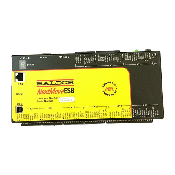
www.supportme.net 4.1.1 Connector locations DIN19 Serial DIN18 DIN17 DIN16 DIN15 X7 Encoder2 X8 DIN 12-19 DIN14 DIN13 DIN12 CREF2 Shield DIN11 DIN10 DIN9 X6 Encoder1 DIN8 DIN7 X9 DIN 4-11 DIN6 DIN5 DIN4 CREF1 Shield DIN3 X5 Encoder0 Shield CREF0 DIN2 X10 DIN 0-3 Shield... -
Page 19: Analog I/O
4.2 Analog I/O The NextMove ESB provides: Two 12-bit resolution analog inputs. Four 12-bit resolution analog outputs. 4.2.1 Analog inputs The analog inputs are available on connector X12, pins 1 & 2 (AIN0) and 4 & 5 (AIN1). Differential inputs. - Page 20 www.supportme.net AIN0+ AIN0+ AIN0 AIN0- AIN0 (ADC.0) (ADC.0) Differential connection Single ended connection Figure 3 - AIN0 analog input wiring +24VDC 1.5kΩ, 0.25W 1kΩ, 0.25W potentiometer AIN0 (ADC.0) Figure 4 - Typical input circuit to provide 0-10V (approx.) input from a 24V source 4-4 Input / Output MN1924...
-
Page 21: Analog Outputs
MicroFlex / servo amplifier ‘X13’ ‘X3’ Demand0 AIN0+ Servo amplifier ±10VDC demand input AGND AIN0- Shield Connect overall shield at one end only Figure 6 - Analog output - typical connection to a Baldor MicroFlex MN1924 Input / Output 4-5... - Page 22 ‘X13’ ‘X1’ Demand0 AIN0+ Servo amplifier ±10VDC demand input AGND AIN0- Shield Connect overall shield at one end only Figure 7 - Analog output - typical connection to a Baldor FlexDrive , Flex+Drive or MintDrive 4-6 Input / Output MN1924...
-
Page 23: Digital I/O
4.3 Digital I/O The NextMove ESB provides: 20 general purpose digital inputs. 11 general purpose digital outputs. 4.3.1 Digital inputs Digital inputs are available on connectors X8, X9 and X10, as shown in section 4.1.1. The digital inputs are arranged in three groups, each with their own common connection. This allows each group to be configured independently for ‘active high’... - Page 24 4.3.1.2 DIN4 - DIN11 Digital inputs DIN4 to DIN11 have a common specification: Opto-isolated digital inputs. Sampling frequency: 1kHz. Digital inputs DIN4 to DIN11 use CREF1 as their common connection. NextMove ESB ‘X9’ 100R Mint DIN11 INX.11 TLP280 CREF1...
- Page 25 The reset input !RSTIN is available on connector X4, and uses CREF1 as its common connection. When the reset input is activated it will cause a hardware reset of the NextMove ESB. This is equivalent to power-cycling the NextMove ESB. Due to the internal pull-up resistor, the reset input may be left floating.
- Page 26 ‘bounce’ could cause unwanted multiple triggering. User MicroFlex / equipment output NextMove ESB ‘X3’ ‘X9’ supply Status+ Status- DIN4 NEC PS2562L-1 CREF1 TLP280 User supply Figure 14 - Digital input - typical connections from a Baldor MicroFlex 4-10 Input / Output MN1924...
- Page 27 User FlexDrive / equipment output NextMove ESB ‘X1’ ‘X9’ supply USRV+ DOUT0 DIN4 NEC PS2562L-1 CREF1 TLP280 User supply Figure 15 - Digital input - typical connections from a Baldor FlexDrive Flex+Drive or MintDrive MN1924 Input / Output 4-11...
- Page 28 If an output is used to drive an inductive load such as a relay, a suitably rated diode must be fitted across the relay coil, observing the correct polarity. The use of shielded cable is recommended. NextMove ESB Voltage regulator ‘X11’...
-
Page 29: Other I/O
The stepper control outputs are available on connectors X2 and X3, as shown in section 4.1.1. There are four sets of stepper motor control outputs, operating in the range 0Hz to 500kHz. Each of the step (pulse) and direction signals from the NextMove ESB is driven by DS26LS31 line drivers, providing RS422 differential outputs. -
Page 30: Encoder Inputs
+5V out Power supply to encoder Three incremental encoders may be connected to NextMove ESB, each with complementary A, B and Z channel inputs. Each input channel uses a MAX3095 differential line receiver with pull up resistors and terminators. Encoders must provide RS422 differential signals. The use of individually shielded twisted pair cable is recommended. -
Page 31: Usb Port
(480Mbps) host PC or hub, communication speed will remain at the USB1.1 specification of the NextMove ESB. Ideally, the NextMove ESB should be connected directly to a USB port on the host PC. If it is connected to a hub shared by other USB devices, communication could be affected by the activity of the other devices. -
Page 32: Serial Port
DGND (NC) NextMove ESB is available with either an RS232 or RS485 serial port (see section 2.2.1). The port is fully ESD protected to IEC 1000-4-2 (15kV). When the NextMove ESB is connected to WorkBench v5, the Tools, Options menu item can be used to configure the serial port. The configuration can also be changed using the Mint keyword SERIALBAUD (see the Mint help file for details). -
Page 33: Multidrop Using Rs485 / Rs422
Only the TXD, RXD and 0V GND connections are required for communication. Pins 4 and 6 are linked on the NextMove ESB. The maximum recommended cable length is 3m (10ft) at 57.6 Kbaud (the factory preset rate). -
Page 34: Connecting Serial Baldor Hmi Operator Panels
Serial Baldor HMI Operator Panels use a 15-pin male D-type connector (marked PLC PORT), but the NextMove ESB Serial connector uses a 9-pin male D-type connector. The NextMove ESB may be connected with or without hardware handshaking, as shown in Figure 22:... -
Page 35: Can
CAN. Both protocols are supported by NextMove ESB, but unlike other Baldor devices both cannot be supported at the same time. This is because NextMove ESB only has a single hardware CAN channel. Separate firmware builds are available to support each of the protocols. -
Page 36: Can Wiring
Baldor are ‘category 5’ and have a maximum current rating of 1A, so the maximum number of NextMove ESB units that may be used on one network is limited to ten. Practical operation of the CAN channel is limited to 500Kbit/s owing to the propagation delay of the opto-isolators. -
Page 37: Canopen
The configuration and management of a CANopen network must be carried out by a single node acting as the network master. This role can be performed by the NextMove ESB when it is configured to be the Network Manager node (node ID 1), or by a third party CANopen master device. -
Page 38: Baldor Can
OutputNode 8 (Baldor part ION003-503) - an 8 x digital output CAN node. RelayNode 8 (Baldor part ION002-503) - an 8 x relay CAN node. IoNode 24/24 (Baldor part ION004-503) - a 24 x digital input and 24 x digital output CAN node. - Page 39 1 and 2 of the RJ45 connectors. On the Baldor CAN node, jumper JP3 can be used to connect an internal 120Ω terminating resistor, provided the node is at the end of the network. Jumpers JP4 and JP5 can be used to configure the node ID and baud rate.
-
Page 40: Connection Summary - Minimum System Wiring
4.6 Connection summary - minimum system wiring As a guide, Figure 26 shows an example of the typical minimum wiring required to allow the NextMove ESB and a single axis servo amplifier to work together. Details of the connector pins are shown in Table 2. - Page 41 NextMove ESB Name of Function Connection on amplifier connector signal (Note: connections may be labeled differently) Control supply ground +24V Control supply +24V input Encoder0 Encoder0 feedback input Encoder output REL NO Normally open relay contact Enable +24V (closed to enable drive)
- Page 42 www.supportme.net 4-26 Input / Output MN1924...
-
Page 43: Operation
RS232 to RS485 converter, connect this as specified by the manufacturer. WorkBench v5 can scan all the PC’s COM ports, so you can use any port. If you are not using the Baldor serial cable CBL001-501, your cable must be wired in accordance with Figure 20 in section 4.4.5. -
Page 44: Preliminary Checks
1. Follow the on-screen instructions to select and install the driver. The driver files are available on the supplied Baldor Motion Toolkit CD. If you are using a copy of the driver located on the hard disk, a floppy disk or another CD, the two driver files must be in the same folder. -
Page 45: Workbench V5
5.2 WorkBench v5 WorkBench v5 is a fully featured application for programming and controlling the NextMove ESB. The main WorkBench window contains a menu system, the Toolbox and other toolbars. Many functions can be accessed from the menu or by clicking a button - use whichever you prefer. Most buttons include a ‘tool-tip’;... -
Page 46: Starting Workbench V5
www.supportme.net 5.2.2 Starting WorkBench v5 1. On the Windows Start menu, select Programs, WorkBench v5, WorkBench v5. WorkBench v5 will start, and the Tip of the Day dialog will be displayed. You can prevent the Tip of the Day dialog appearing next time by removing the check mark next to Show tips at startup. - Page 47 USB, it will be scanned automatically. Click Scan to search for the NextMove ESB. When the search is complete, click ‘NextMove ESB’ in the list to select it, and then click Select. Note: If the NextMove ESB is not listed, check the serial or USB cable between the NextMove ESB and the PC.
-
Page 48: Configuring An Axis
The NextMove ESB is capable of controlling 4 stepper and 3 servo axes. This section describes the basic setup for both types of axis. Commands typed in the Command window have immediate effect - they do not need to be separately downloaded to the NextMove ESB. 5.3.1 Selecting a scale MintMT defines all positional and speed related motion keywords in terms of encoder quadrature counts (for servo motors) or steps for stepper motors. -
Page 49: Setting The Drive Enable Output
5.3.2 Setting the drive enable output A drive enable output allows NextMove ESB to enable the external amplifier to allow motion, or disable it in the event of an error. Each axis can be configured with its own drive enable output, or can share an output with other axes. - Page 50 5. Click Apply at the bottom of the screen. This sends the output configuration to the NextMove ESB. See section 5.10 for details about saving configuration parameters.
-
Page 51: Testing The Drive Enable Output
If this is not working, or the action of the button is reversed, check the electrical connections between the NextMove ESB and amplifier. If you are using the relay, check that you are using the correct normally open (REL NO) or normally closed (REL NC) connections. -
Page 52: Stepper Axis - Testing
www.supportme.net 5.4 Stepper axis - testing This section describes the method for testing a stepper axis. The stepper control is an open loop system so no tuning is necessary. 5.4.1 Testing the output This section tests the operation and direction of the output. It is recommended that the system is initially tested with the motor shaft disconnected from other machinery. -
Page 53: Servo Axis - Testing And Tuning
www.supportme.net 5.5 Servo axis - testing and tuning This section describes the method for testing and tuning a servo axis. The amplifier must already have been tuned for basic current or velocity control of the motor. 5.5.1 Testing the demand output This section tests the operation and direction of the demand output for axis 4. - Page 54 www.supportme.net 5. To repeat the tests for negative (reverse) demands, type: TORQUE.4=-5 This should cause a demand of -5% of maximum output (-0.5V) to be produced at the DEMAND0 output. Correspondingly, the Spy window’s Velocity display should show a negative value. 6.
-
Page 55: An Introduction To Closed Loop Control
[ Demand stopped so you stopped too, but not quite level ]. The NextMove ESB tries to correct the error, but because the error is so small the amount of torque demanded might not be enough to overcome friction. - Page 56 www.supportme.net The remaining gain terms are Velocity Feed forward (KVELFF) and Acceleration Feed forward (KACCEL) described below. In summary, the following rules can be used as a guide: KPROP: Increasing KPROP will speed up the response and reduce the effect of disturbances and load variations.
- Page 57 Figure 28 - The NextMove ESB servo loop MN1924 Operation 5-15...
-
Page 58: Servo Axis - Tuning For Current Control
www.supportme.net 5.6 Servo axis - tuning for current control 5.6.1 Selecting servo loop gains All servo loop parameters default to zero, meaning that the demand output will be zero at power up. Most servo amplifiers can be set to current (torque) control mode or velocity control mode;... - Page 59 0.15 seconds. 7. Click Go. The NextMove ESB will perform the move and the motor will turn. As the soon as the move is completed, WorkBench v5 will upload captured data from the NextMove ESB. The data will then be displayed in the Capture window as a graph.
- Page 60 www.supportme.net 5.6.2 Underdamped response If the graph shows that the response is underdamped (it overshoots the demand, as shown in Figure 29) then the value for KDERIV should be increased to add extra damping to the move. If the overshoot is excessive or oscillation has occurred, it may be necessary to reduce the value of KPROP.
- Page 61 www.supportme.net 5.6.3 Overdamped response If the graph shows that the response is overdamped (it reaches the demand too slowly, as shown in Figure 30) then the value for KDERIV should be decreased to reduce the damping of the move. If the overdamping is excessive, it may be necessary to increase the value of KPROP.
- Page 62 www.supportme.net 5.6.4 Critically damped response If the graph shows that the response reaches the demand quickly and only overshoots the demand by a small amount, this can be considered an ideal response for most systems. See Figure 31. Demand position Measured position Figure 31 - Critically damped (ideal) response 5-20 Operation...
-
Page 63: Servo Axis - Eliminating Steady-State Errors
0.1. 2. Click in the KINTLIMIT box and enter a value of 5. With NextMove ESB, the action of KINT and KINTLIMIT can be set to operate in various modes: Never - the KINT term is never applied Always - the KINT term is always applied Smart - the KINT term is only applied when the demand speed is zero or constant. -
Page 64: Servo Axis - Tuning For Velocity Control
www.supportme.net 5.8 Servo axis - tuning for velocity control Drives designed for velocity control incorporate their own velocity feedback term to provide system damping. For this reason, KDERIV (and KVEL) can often be set to zero. Correct setting of the velocity feed forward gain KVELFF is important to get the optimum response from the system. - Page 65 8. Click Go. The NextMove ESB will perform the move and the motor will turn. As the soon as the move is completed, WorkBench v5 will upload captured data from the NextMove ESB. The data will then be displayed in the Capture window as a graph.
- Page 66 www.supportme.net 9. Using the check boxes below the graph, select the Measured velocity and Demand velocity traces. Demand velocity Measured velocity Figure 32 - Correct value of KVELFF It may be necessary to make changes to the calculated value of KVELFF. If the trace for Measured velocity appears above the trace for Demand velocity, reduce the value of KVELFF.
-
Page 67: Adjusting Kprop
0.1. 2. Click Go. The NextMove ESB will perform the move and the motor will turn. As the soon as the move is completed, WorkBench v5 will upload captured data from the NextMove ESB. The data will then be displayed in the Capture window as a graph. - Page 68 www.supportme.net Demand position Measured position Figure 33 - Correct value of KPROP The two traces will probably appear with a small offset from each other, which represents the following error. Adjust KPROP by small amounts until the two traces appear on top of each other (approximately), as shown in Figure 33.
-
Page 69: Digital Input/Output Configuration
www.supportme.net 5.9 Digital input/output configuration The Digital I/O window can be used to setup other digital inputs and outputs. 5.9.1 Digital input configuration The Digital Inputs tab allows you to define how each digital input will be triggered, and if it should be assigned to a special purpose function such as a Home or Limit input. -
Page 70: Digital Output Configuration
4. Now drag the IN1 icon onto the Fwd Limit icon This will setup IN1 as the Forward Limit input of axis 0. 5. Click Apply to send the changes to the NextMove ESB. Note: If required, multiple inputs can be configured before clicking Apply. -
Page 71: Saving Setup Information
5.10 Saving setup information When power is removed from the NextMove ESB all data, including configuration and tuning parameters, is lost. You should therefore save this information in a file, which can be loaded when the unit is next used. -
Page 72: Loading Saved Information
A Startup block should be included in every Mint program, so that whenever a program is loaded and run the NextMove ESB will be correctly configured. Remember that every drive/motor combination has a different response. If the same program is used on a different NextMove ESB installation, the Startup block will need to be changed. -
Page 73: Troubleshooting
If you have followed all the instructions in this manual in sequence, you should have few problems installing the NextMove ESB. If you do have a problem, read this section first. In WorkBench v5, use the Error Log tool to view recent errors and then check the help file. -
Page 74: Nextmove Esb Indicators
Spline. A spline move is being performed. See the SPLINE keyword and related commands. Axis enabled. Torque mode. The NextMove ESB is in Torque mode. See the TORQUE keyword and related commands. Hold to Analog. The axis is in Hold To Analog mode. See the HTA keyword and related commands. -
Page 75: Communication
If the status display shows one of the digits 0 - 7 with a flashing decimal point during startup, this indicates that the NextMove ESB has detected a fault and cannot be started. In this unlikely event, please contact Baldor technical support. -
Page 76: Motor Control
Confirm that the drive enable output has been configured (see section 5.3.2). Ensure that while the NextMove ESB is not in error the drive is enabled and working. When the NextMove ESB is first powered up the drive should be disabled if there is no program running (there is often an LED on the front of the drive to indicate status). -
Page 77: Workbench V5
Symptom Check Motor is under control, but Verify that the NextMove ESB and drive are correctly when moved to a position and grounded to a common earth point. then back to the start it does not return to the same position. -
Page 78: Canopen
Check The CANopen bus is ‘passive’ This means that the internal CAN controller in the NextMove ESB is experiencing a number of Tx and/or Rx errors, greater than the passive threshold of 127. Check: 12-24V is being applied to pin 5 of the RJ45 CAN connector, to power the opto-isolators. - Page 79 MintMT state, check the following: NODESCAN keyword. Only nodes that conform to DS401, DS403 and other Baldor CANopen nodes are supported by the MintMT NODESCAN keyword. Check that the node in question has been assigned a unique node ID.
-
Page 80: Baldor Can
The Baldor CAN bus is This means that the internal CAN controller in the ‘passive’ NextMove ESB is experiencing a number of Tx and/or Rx errors, greater than the passive threshold of 127. Check: 12-24V is being applied to pin 5 of the RJ45 CAN connector, to power the opto-isolators. -
Page 81: Specifications
Specifications 7.1 Introduction This section provides technical specifications of the NextMove ESB. 7.1.1 Input power Description Value Input power Nominal input voltage 24V (±20%) Power consumption 50W (2A @24V) 7.1.2 Analog inputs Description Unit Value Type Differential Common mode voltage range ±10... -
Page 82: Digital Inputs
www.supportme.net 7.1.4 Digital inputs Description Unit Value Type Opto-isolated USR V+ supply voltage Nominal Minimum Maximum Input voltage Active > 12V Inactive < 2V Input current (maximum per input, USR V+ = 24V) 7.1.5 Digital outputs - general purpose Description Unit Value USR V+ supply voltage... -
Page 83: Stepper Control Outputs
7.1.10 CAN interface Description Unit Value Signal 2-wire, isolated Channels Protocols CANopen or Baldor CAN (selected by choice of firmware) Bit rates Kbit/s CANopen 10, 20, 50, 100, 125, 250, 500, 1000 Baldor CAN 10, 20, 50, 125, 250, 500, 1000 7.1.11 Environmental... -
Page 84: Weights And Dimensions
www.supportme.net 7.1.12 Weights and dimensions Description Value Weight Approximately 700g (1.5 lb) Nominal overall dimensions 245mm x 135mm x 43mm (9.65in x 5.32in x 1.69in) 7-4 Specifications MN1924... -
Page 85: A General
www.supportme.net General A.1 Axis renumbering The factory preset axis numbering assigns axes 0 - 3 as stepper axes and axes 4 - 6 as servo axes. However, it is possible to alter the axis numbering scheme. For example, you might wish axes 0 and 1 to refer to the servo axes, and axes 2 to 5 to refer to the stepper axes. - Page 86 www.supportme.net 2. Click in the Command window. 3. Type the command: CONFIG[0,1,2,3,4,5,6]=_cfOFF; This will turn off all axes. There will now be no electrical output for any of the axes. 4. Now type: CONFIG.4=_cfSTEPPER where 4 is the axis to be configured. Press Enter to enter the value.
-
Page 87: Feedback Cables
CBL020MF-A2 Table 3 - Servo amplifier to NextMove ESB feedback cables If you are not using a Baldor cable, be sure to obtain a cable that is a shielded twisted pair 0.34mm (22 AWG) wire minimum, with an overall shield. Ideally, the cable should not exceed 30.5m (100ft) in length. - Page 88 www.supportme.net A-4 General MN1924...
-
Page 89: Bce Guidelines
B.1.2 NextMove ESB compliance When installed as directed in this manual, NextMove ESB units meet the emission limits for an ‘industrial’ environment, as defined by the EMC directives (EN50081-2: 1994). To meet the more stringent emission limits of the ‘residential, commercial and light industrial’ environment (EN50081-1: 1992), the NextMove ESB must be mounted in a suitable metal cabinet incorporating 360°... -
Page 90: B.1.3 Use Of Ce Compliant Components
Earthing/grounding of all system elements to a central earth/ground point (star point). Shielding of all cables and signal wires. B.1.5 Wiring of shielded (screened) encoder cables NextMove ESB Encoder Connector Cable X5 / X6 / X7... - Page 91 4-7 location requirements, 3-1 digital outputs, 4-12 mounting, 3-2 Drive enable output setting, 5-7 testing, 5-9 Calculating KVELFF, 5-22 CAN interface Baldor CAN, 4-22 Encoder CANopen, 4-21 cables, A-3 connector, 4-19 inputs, 4-14 introduction, 4-19 Environmental, 3-1, 7-3 opto-isolation, 4-20...
- Page 92 Saving setup information, 5-29 critically damped response, 5-20 Scale, selecting, 5-6 eliminating steady-state errors, 5-21 Serial port, 4-16 overdamped response, 5-19 connecting serial Baldor HMI panels, 4-18 selecting servo loop gains, 5-16 Servo axis, 5-11 underdamped response, 5-18 adjusting KPROP, 5-25 MN1924...
- Page 93 Underdamped response, 5-18 Weights and dimensions, 7-4 Units and abbreviations, 2-4 WorkBench v5, 5-3 digital input/output configuration, 5-27 help file, 5-3 installing the driver, 5-2 loading saved information, 5-30 port, 4-15 saving setup information, 5-29 starting, 5-4 MN1924 Index...
- Page 94 MN1924 Index...
- Page 95 If you have any suggestions for improvements to this manual, please let us know. Write your comments in the space provided below, remove this page from the manual and mail it to: Manuals Baldor UK Ltd Mint Motion Centre 6 Bristol Distribution Park...
- Page 96 Thank you for taking the time to help us. Comments MN1924...
- Page 98 Baldor Japan Corporation Baldor Electric Company Tel: +81 45 412 4506 Tel: +1 479 646 4711 Fax: +81 45 412 4507 Fax: +1 479 648 5792 For additional office locations visit www.baldor.com Printed in UK E Baldor UK Ltd LT0189A02...
Need help?
Do you have a question about the Nextmove ESB and is the answer not in the manual?
Questions and answers