Barco F50 User Manual
Hide thumbs
Also See for F50:
- User manual (66 pages) ,
- Quick start manual (2 pages) ,
- User and installation manual (2 pages)
Table of Contents
Advertisement
Quick Links
Advertisement
Table of Contents

Subscribe to Our Youtube Channel
Related Manuals for Barco F50


Summary of Contents for Barco F50
- Page 1 User Manual 601–0307–00/02 25/02/2016...
- Page 2 Barco Fredrikstad AS Habornveien 53, N-1630 Gamle Fredrikstad, Norway Phone: +47 6930 4550 Fax: +47 6930 4580 Support: Support.fre@barco.com Visit us at the web: www.barco.com Printed in N0...
-
Page 3: Software License Agreement
The period of guarantee begins on the date of transfer of risks, in the case of special systems and software on the date of commissioning, at latest 30 days after the transfer of risks. In the event of justified notice of complaint, Barco can repair the fault or provide a replacement at its own discretion within an appropriate period. - Page 4 interruption or other pecuniary loss arising directly or indirectly. Any liability of the seller will be exclusively limited to replacement of the product or refund of purchase price. Trademarks Brand and product names mentioned in this manual may be trademarks, registered trademarks or copyrights of their respective holders. All brand and product names mentioned in this manual serve as comments or examples and are not to be understood as advertising for the products or their manufacturers.
-
Page 5: Table Of Contents
Choose an aspect ratio ......................80 601–0307–00 F50 25/02/2016... - Page 6 16.3 Production address ....................... . .131 601–0307–00 F50 25/02/2016...
-
Page 7: Introduction
1. Introduction 1. INTRODUCTION Overview • Welcome • About this manual 601–0307–00 F50 25/02/2016... -
Page 8: Welcome
Welcome! Congratulations on your purchase of a Barco F50 projector! The F50 projectors are part of a proud tradition of quality projectors built for superior performance, and feature compact footprint, high performance optics and lenses, excellent resolution, Active Stereo 3D capabilities and built-in frame-lock synchronization. -
Page 9: About This Manual
All physical measurement units given in this manual are according to the International Standard of Units (SI units). Conversion from this to other measurement units is the responsibility of the user. Illustrations used in the manual are for general reference only, and may differ from your product. 601–0307–00 F50 25/02/2016... - Page 10 1. Introduction 601–0307–00 F50 25/02/2016...
-
Page 11: Safety
To prevent personal injury to users or physical damage to the projector while installing and using your projector, ensure that you understand and follow all safety guidelines, instructions and warnings included in this chapter and this manual. Overview • General Considerations • Important safety instructions • Product safety labels 601–0307–00 F50 25/02/2016... -
Page 12: General Considerations
The part number and serial number are printed on a label which is stuck on the respective part. Record these numbers in the spaces provided below. Refer to them whenever you call upon your Barco dealer regarding this product. Product article number... -
Page 13: Important Safety Instructions
Lightning - For added protection for this video product during a lightning storm, or when it is left unattended and unused for long periods of time, remove all power from the projector. This will prevent damage to the projector due to lightning and AC power-line surges. 601–0307–00 F50 25/02/2016... - Page 14 This product contains chemicals, including lead, known to the State of California to cause birth defects or other reproductive harm. Recycle properly, do not dispose of in ordinary waste! ARNING Service personnel must use eye and skin protection during servicing. 601–0307–00 F50 25/02/2016...
- Page 15 Never expose the projector to rain or moisture. In the event of fire, use sand, CO water on an electrical fire. Always have service performed on this projector by authorized Barco service personnel. Always insist on genuine Barco replacement parts. Never use non-Barco replacement parts as they may degrade the safety of this projector.
- Page 16 If the product exhibits a distinct change in performance, indicating a need for service. • Replacement parts: When replacement parts are required, be sure the service technician has used original Barco replacement parts or authorized replacement parts which have the same characteristics as the Barco original part. Unauthorized substitu- tions may result in degraded performance and reliability, fire, electric shock or other hazards.
-
Page 17: Product Safety Labels
60 minutes before proceeding to remove the Lamp House. General Warning Hazard Electric Voltage Hazard Hot Surface Hazard UV Hazard Hazardous moving parts. Keep away from moving fan blades. Keep fingers and other body parts away. 601–0307–00 F50 25/02/2016... - Page 18 2. Safety 601–0307–00 F50 25/02/2016...
-
Page 19: Getting To Know The Projector
3. Getting to know the projector 3. GETTING TO KNOW THE PROJECTOR Overview • Introducing a small revolution • About the projector • Projector components • User interface • Accessories 601–0307–00 F50 25/02/2016... -
Page 20: Introducing A Small Revolution
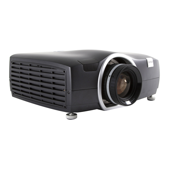
3. Getting to know the projector Introducing a small revolution A world best in fit and function The F50 is the market’s brightest, sharpest and most compact 120Hz single chip DLP® projector. Image 3-1 Unmatched imagery • 1 Chip DLP®... -
Page 21: About The Projector
Projector service (LFM) and consumables The F50 has no user-serviceable parts. The projector fans and color wheels require service or replacement, typically after 8000 operating hours. Both of these service tasks must only be carried out by the manufacturer or a manufacturer-authorized service technician. -
Page 22: Projector Components
3. Getting to know the projector Projector components Projector components Image 3-2 Item No. Description IR receiver, front Adjustable feet Projector lens holder Projector exhaust Mains power connector Connector panel IR Receiver, rear Lamp house cover Keypad 601–0307–00 F50 25/02/2016... -
Page 23: User Interface
User interface General The primary user interface for the F50 is the On Screen Display (OSD) system. The OSD is a menu—based interface. Topics are sorted and displayed by main (topic) — sub (topic) — sub (topic). There are six (6) main menu topics, each represented by a graphical icon: 3D, picture, installation, settings, language, status. -
Page 24: Accessories
3. Getting to know the projector Accessories Ceiling mount cover The ceiling mount cover is designed to improve exhaust capabilities of the F50 when it is ceiling mounted. Image 3-5 Item number Description R9801322 Ceiling mount cover, black R9801323 Ceiling mount cover, white Noise reduction kit The noise reduction kit comprises the ceiling mount cover and an air inlet filter and muffler to reduce noise and improve exhaust... - Page 25 3. Getting to know the projector For use with WQXGA @ 60 Hz (max 330 MHz). Item number Description R9801224 WB2560 Image Processor 601–0307–00 F50 25/02/2016...
- Page 26 3. Getting to know the projector 601–0307–00 F50 25/02/2016...
-
Page 27: Lenses
4. Lenses 4. LENSES Overview • Lens range • Installing a lens • Lens shift • Adjust zoom, focus and iris • Lens lock 601–0307–00 F50 25/02/2016... -
Page 28: Lens Range
General The information in this section is subject to change. For the most up-to-date information, go to the Barco website and select your product to see its technical specifications or other information. -
Page 29: Installing A Lens
Depress the lens release button (reference 1, image 4-2) and then turn the lens anticlockwise until the lens bayonet is clear of the projector chassis. Image 4-2 To prevent dust contamination in the projector light processor, always replace the lens bayonet cap, lens cap and projector lens cap (if applicable) immediately after removing the lens. 601–0307–00 F50 25/02/2016... -
Page 30: Lens Shift
For information on the available shift and offset values for each lens, see"Lens shift and offset matrix", page 40. All F50 lenses have limited downwards shift. Lens shift can also be carried out via the RS232 communication interface. See the relevant ASCII Commands Protocol for more details. -
Page 31: Adjust Zoom, Focus And Iris
✖ ✖ ✖ ✔ ✔ ✔ ✔ Zoom control ✔ ✔ ✔ ✔ ✔ ✔ ✔ Focus control For best results, lens adjustments should be done in the following order: zoom, focus and then iris (where applicable). 601–0307–00 F50 25/02/2016... -
Page 32: Lens Lock
The lens lock function is not needed for most installations, however it can be very useful in high-motion installations. To lock the lens in position, you will need a 1.5 mm Allen Key. Use the Allen key to tighten each of the adjustment screws, one at a time, until the respective ring cannot be turned. 601–0307–00 F50 25/02/2016... -
Page 33: Installation
Positioning the projector • Mounting the projector on a flat surface • Installing the projector to a ceiling mount or frame • Throw distance • Lens shift and offset matrix • Scheimpflug (Boresight) adjustment • Scheimpflug adjustment 601–0307–00 F50 25/02/2016... -
Page 34: Installing The Projector
11. Select the video and/or data sources. See "Connect to a source", page 50 12.Adjust the projected image on the screen. See "Set up the picture", page 71 for more information. 1. A range of rigging frames are available as optional accessory 601–0307–00 F50 25/02/2016... -
Page 35: Installation Conditions
This section contains important physical and environmental information that will help you determine the optimal installation position and conditions for your projector. Barco projectors are manufactured according to specific design standards, which also include environmental conditions. Failing to follow the terms and conditions outlined in this chapter can result in loss of product warranty. - Page 36 5. Installation 341.4 Image 5-2 601–0307–00 F50 25/02/2016...
-
Page 37: Initial Inspection
Upon receipt of the projector, we recommend that customers inspect the projector for any signs of damage that may have occurred in transit. If damage is found, file a claim with the shipping carrier immediately. Notify the Barco Sales and Service office, or your preferred Barco agent, of the damage as soon as possible. -
Page 38: Positioning The Projector
Focus and sharpness of the image can be adversely affected if the lens axis is not fully perpendicular to the projection surface. The following guidelines can help you determine the best physical location for the projector. 601–0307–00 F50 25/02/2016... - Page 39 The projector can be rotated up to ±20 degrees on the side-to-side-axis without influencing lamp performance, as shown in image 5-4. The projector can be rotated 360 degrees on the through-the-lens-axis. + 20˚ 360˚ - 20˚ Image 5-4 601–0307–00 F50 25/02/2016...
-
Page 40: Mounting The Projector On A Flat Surface
(lens shift) rather than extra tilt. If tilt is required, make sure that it does not exceed 20 degrees on the side-to-side axis. See "Positioning the projector", page 34 for more information. 601–0307–00 F50 25/02/2016... -
Page 41: Installing The Projector To A Ceiling Mount Or Frame
The screw should not protrude more than 9 mm into the projector chassis. Caution: Correct screw length is extremely important. Failing to observe these limitations may cause damage to your projector. 5. Install all three screws, making sure not to overtighten. 601–0307–00 F50 25/02/2016... -
Page 42: Throw Distance
The following graphs illustrate the image size (W) and projection distance (D) for each of the projector lenses. Tolerances are typically +/- 5% due to optical (lens) variation. WQXGA/Panorama 12,00 10,00 8,00 6,00 4,00 2,00 0,00 0,00 1,00 2,00 3,00 4,00 5,00 6,00 7,00 8,00 9,00 10,00 11,00 12,00 Projection distance (meters) Image 5-7 601–0307–00 F50 25/02/2016... - Page 43 5. Installation WUXGA/1080 12,00 10,00 8,00 6,00 4,00 2,00 0,00 0,00 1,00 2,00 3,00 4,00 5,00 6,00 7,00 8,00 9,00 10,00 11,00 12,00 Projection distance (meters) Image 5-8 601–0307–00 F50 25/02/2016...
-
Page 44: Lens Shift And Offset Matrix
4.2 * (42 ÷ 2 = 21) 21 ÷ 100 = .89 0% Lens Shift equals on axis (i.e. no shift). 100% Lens Shift equals half of image height / width. F50–series offset matrix The following table shows the available offset for each lens by projector resolution. - Page 45 For more detail on this procedure, see "Lens shift", page 26. For information on using the RS-232 or LAN control interfaces, please refer to the relevant ASCII Commands Protocol available for download at www.barco.com 601–0307–00 F50 25/02/2016...
-
Page 46: Scheimpflug (Boresight) Adjustment
Scheimpflug adjustment points There are three (3) Scheimpflug set and adjustment screws on the F50. The adjustment screw (a) is adjusted using an Allen Key screw, hex size 3. The set screw (b) is locked and unlocked using an Allen Key screw, hex size 5. The set screw is NOT used during Scheimpflug adjustment. -
Page 47: Scheimpflug Adjustment
Preparation 1. Prepare the test area. Barco recommends a projector-screen distance of 2 metres be used for all Scheimpflug adjustments. Verify that the throw ratio of the installed lens matches the requirements of the installation area (projection distance and screen size). - Page 48 2 to 6 until the image is correct. 7. Tighten the three set screws in the following order: left (1b), right (2b) and then top (3b). Use a size 5 hex key to do this. 601–0307–00 F50 25/02/2016...
-
Page 49: Input And Communication
• Extended Display Identification Data (EDID) • HDBaseT • • DVI-D • HDMI • Display Port 1 • Display Port 2 • LAN (Control) • RS232 (Control) • USB-A • Sync 1 and 2 • Sync 3 601–0307–00 F50 25/02/2016... -
Page 50: Local Keypad
Multi-use key. With Lens Shift active, used to move the lens up. With OSD active, used to navigate selection up. Can also be used for PIN numeric entry (4, 5). Multi-use key. With OSD active, confirms a selection. With OSD not active, activates Lens Shift function. 601–0307–00 F50 25/02/2016... -
Page 51: Status Indicator Light
During normal operations, the status indicator will glow to indicate the current status of the projector. The indicator light can be turned off (muted) to eliminate light pollution in totally dark installations. Critical error indications (red status indicator) will still display when the LED Indicator is muted. 601–0307–00 F50 25/02/2016... -
Page 52: Wireless Remote Control
Each of the IR receivers on the projector operates individually of the other, and can be enabled or disabled as required. To enable or disable the front IR receiver, go to Main Menu — Installation — IR Front. To enable or disable the rear IR receiver, go to Main Menu — Installation — IR Rear. 601–0307–00 F50 25/02/2016... -
Page 53: Connector Panel
All source and control connections are made via the connector panel located on the rear cover. There are 13 available interfaces (7 source, 6 control), each of them is labelled for easy identification. For individual interface specifications, see the sections below. HDBaseT USBA HDMI DVI-D 3G-SDI SYNC RS-232 SYNC Image 6-3 601–0307–00 F50 25/02/2016... -
Page 54: Connect To A Source
Multiple signals can be connected in parallel to allow for a selection of sources to be viewed in sequence. The quality and length of cables may cause distorted or even failing signal quality. For best results Barco recommends the cable quality and cable length limitations be taken into consideration when setting up the installation. -
Page 55: Extended Display Identification Data (Edid)
, 1280x1600@@60 Hz WQXGA@60Hz, WUXGA@60Hz, 1080@60Hz, SX+, SXGA, 1366x768, 720@60Hz, 720@50Hz, XGA, SVGA, VGA. 2. For Picture by Picture use 3. All settings except Auto use DVI as type. 4. All settings except Auto use HDMI as type. 601–0307–00 F50 25/02/2016... -
Page 56: Hdbaset
Not Supported RS-232 Extension Not Supported 10/100Mbps Ethernet Pass-Through Fallback to 100BaseTx, IEEE 802.3u Not Supported USB Over Centre Tap Not Supported Power Over Ethernet Not Supported Audio Not Supported Status LED Operation: Green, Left. Link/Mode: Yellow, Right. 601–0307–00 F50 25/02/2016... -
Page 57: Vga
Dot (pixel) clock rate Analog VGA 10 - 162 MHz max Maximum resolution 1920x1200 @ 60Hz Nominal sync impedance Selectable 75 ohms or 2k2 ohms Input levels RGB with sync 1.0Vp-p ± 2dB (0.35 Vpp – 1.4 Vpp) 601–0307–00 F50 25/02/2016... -
Page 58: Dvi-D
Max. pixel rate 330 MHz (dual link), 165 Mhz (single link) Scan format Interlaced or progressive Max. input resolution 2560x1600 (dual link), 1920x1200 (single link) @ 60 Hz Bit depth 8 bit EDID Supported HDCP HDCP 1.1 601–0307–00 F50 25/02/2016... -
Page 59: Hdmi
Parameter Value Connector Standard HDMI Signal characteristics HDMI 1.4 (video only); Digital, TMDS Max. pixel rate 270 MHz Ethernet Audio Scan format Interlaced or progressive Max. input resolution 2560x1600 @60Hz – 24bit EDID Supported HDCP HDCP 1.4 601–0307–00 F50 25/02/2016... -
Page 60: Display Port 1
15 m (24 AWG) - RBR; 2 m (24 AWG) – HBR, HBR2 3D formats supported Frame field sequential, Frame stacked, Side by side Scan format Interlaced or progressive Max. input data resolution 2560x1600 @120Hz Bit depth 8, 10, 12 bit EDID Supported HDCP HDCP 1.4 601–0307–00 F50 25/02/2016... -
Page 61: Display Port 2
15 m (24 AWG) - RBR; 2 m (24 AWG) – HBR, HBR1 3D formats supported Frame field sequential, Frame stacked, Side by side Scan format Interlaced or progressive Max. input data resolution 2560x1600 @60Hz Bit depth 8, 10, 12 bit EDID Supported HDCP 601–0307–00 F50 25/02/2016... -
Page 62: Lan (Control)
6. Input and communication 6.13 LAN (Control) Specifications Parameter Value Connector 1 RJ45 Connector for projector control (not content) Protocols DHCP, TCP/IP, UDP/IP Speed 10/100/1000 MBit 601–0307–00 F50 25/02/2016... -
Page 63: Rs232 (Control)
When using RS232 Serial Communication, the projector baud rate may need to be adjusted to match that of your computer. The default value is 19200. Baud rate is set from Main Menu — Settings — Baud Rate. The ASCII Commands Protocol for the projector are available for download from www.barco.com Specifications... -
Page 64: Usb-A
6. Input and communication 6.15 USB-A Specifications Parameter Value Connector USB type A Function Firmware upgrade using USB stick 601–0307–00 F50 25/02/2016... -
Page 65: Sync 1 And 2
6. Input and communication 6.16 Sync 1 and 2 Specifications Parameter Value Connector Function Input / output sync control 601–0307–00 F50 25/02/2016... -
Page 66: Sync 3
6. Input and communication 6.17 Sync 3 Specifications Parameter Value Connector Function Input / output sync control; can be used to power (5V) IR emitter when Glass Sync selected in OSD 601–0307–00 F50 25/02/2016... -
Page 67: Change Projector Settings
7. Change projector settings 7. CHANGE PROJECTOR SETTINGS Overview • Select a power mode • Lock the projector • Customize the On Screen Display (OSD) • Review and change network settings • Review system status • Revert to factory settings 601–0307–00 F50 25/02/2016... -
Page 68: Select A Power Mode
If DPMS is enabled in the SETTINGS menu, the projector will automatically wake out of Standby ECO mode and power back on when a valid source is acquired from the following inputs: • DP1 and DP2 • HDMI • • • SDI 1 and SDI 2 601–0307–00 F50 25/02/2016... -
Page 69: Lock The Projector
If the PUK code is entered incorrectly 3 consecutive times, the projector will be locked and can only be un- locked by an authorized Barco service partner. Proof of purchase will be required to unlock the projector. The PUK code for each projector is individual and cannot be used with other projectors. Your projector PUK code is provided with your original packaging. -
Page 70: Customize The On Screen Display (Osd)
A solid, colored background is displayed whenever the projector is searching for a source. Use this menu to change the background between black, white and gray. Change the splash screen Main Menu — Settings — Splash By default, the manufacturer’s logo will appear during projector startup. This can be changed to a solid colored screen, if desired. 601–0307–00 F50 25/02/2016... -
Page 71: Review And Change Network Settings
When DHCP is enabled, current network settings are automatically displayed at Main Menu — Settings — Network. When DHCP is disabled, users can set a fixed IP address for the projector at Main Menu — Settings — Network — Change LAN settings. 601–0307–00 F50 25/02/2016... -
Page 72: Review System Status
Detailed source information is available in the OSD, Main Menu — Status — Source Information Source timing information and other source analysis data can be reviewed at Main Menu — Status — Source Information — Ad- vanced. 601–0307–00 F50 25/02/2016... -
Page 73: Revert To Factory Settings
(power users) can define whether a factory reset will be ’full’ or ’limited’. For normal access users, the factory reset default is set to ’limited’. The following projector settings can be individually selected or deselected for inclusion in the reset: • Picture • • Communication • Real Color 601–0307–00 F50 25/02/2016... - Page 74 7. Change projector settings 601–0307–00 F50 25/02/2016...
-
Page 75: Set Up The Picture
• Select the image orientation • Use test images • Set up Picture-by-Picture • Apply a display profile • Adjust lamp power • Use gamma curves • Adjust brightness, saturation and contrast • Choose an aspect ratio 601–0307–00 F50 25/02/2016... -
Page 76: Select The Image Orientation
8. Set up the picture Select the image orientation About Main Menu — Installation — Image Orientation The projector supports the following installation orientations: • Desktop front (default) • Ceiling front • Desktop rear • Ceiling rear 601–0307–00 F50 25/02/2016... -
Page 77: Use Test Images
Use the arrow keys to navigate to the required aspect ratio. The display will change dynamically. Available test images: • • • 16:9 • 16:10 • 1.85:1 • 2.35:1 • • Combined (displays all available aspect ratios simultaneously) • Focus 601–0307–00 F50 25/02/2016... -
Page 78: Set Up Picture-By-Picture
DVI (dual link mode) ✖ ✖ ✔ ✔ ✔ ✔ ✔ ✔ ✔ ✖ ✖ 3G SDI (A) ✔ ✔ ✔ ✔ ✔ ✔ ✔ ✖ ✖ 3G SDI (B) ✔ ✔ ✔ ✔ ✔ ✔ ✔ 601–0307–00 F50 25/02/2016... -
Page 79: Apply A Display Profile
Dynamic Presentation Bright Dynamic Bright Bright Computer 2 Cinema Film 2.2 DICOM Digital Imaging and Communications DICOM 180 in Medicine (DICOM) compliant. SRP™ Smear Reduction Processing. Not SRP Half Film 2.2 available with High Brightness color wheel. 601–0307–00 F50 25/02/2016... -
Page 80: Adjust Lamp Power
Running the projector lamp at different power levels will alter the brightness of the image on the screen. Higher levels give higher brightness and shorter lamp life time. Lower levels save energy, extend lifetime and reduce brightness. The lamp power can be adjusted between 280 W and 350 W. Each step has a value of 3 W. 601–0307–00 F50 25/02/2016... -
Page 81: Use Gamma Curves
Some curves are reserved for Advanced or Service users, and will only be viewable after the access code is input. Using any of the computer curves for video applications will results in significant image noise. Computer 1 Computer 2 Film 2.2 Input Input Input Film 2.4 Film 2.6 Film 2.8 Input Input Input Image 8-1 601–0307–00 F50 25/02/2016... - Page 82 Video 1 Video 2 Dynamic Input Input Input HB DICOM 60 HB DICOM 10 HB DICOM 180 Input Input Input Image 8-2 HB DICOM 250 HB DICOM 300 HB DICOM 400 Input Input Input Linear Input Image 8-3 601–0307–00 F50 25/02/2016...
-
Page 83: Adjust Brightness, Saturation And Contrast
Saturation levels impact on the white levels and the intensity of the color display; the higher the value, the more vivid the color display will be. All adjustments (-50 to +50) are dynamic. Any changes will be saved to the active display profile when you exit the OSD menu. 601–0307–00 F50 25/02/2016... -
Page 84: Choose An Aspect Ratio
Displays the image with a 16:9 (widescreen) aspect ratio (scaled) image regardless of input aspect ratio and resolution. Fill 4:3 Displays the image with a 4:3 aspect ratio (scaled) image regardless of the input aspect ratio and resolution. One to one Turns off all scaling; projects the input image mapped pixel-by-pixel without scaling. 601–0307–00 F50 25/02/2016... -
Page 85: Advanced Picture Adjustments
9. Advanced picture adjustments 9. ADVANCED PICTURE ADJUSTMENTS 601–0307–00 F50 25/02/2016... - Page 86 9. Advanced picture adjustments 601–0307–00 F50 25/02/2016...
-
Page 87: Apply Smear Reduction Processing (Srp)
(HD / WUXGA / 2560 x 1080 / WQXGA) ✖ ✔ F50 120Hz VizSim Bright (HD / WUXGA / 2560 x 1080 / WQXGA) ✖ ✖ F50 120Hz (HD / WUXGA / 2560 x 1080 / WQXGA) 601–0307–00 F50 25/02/2016... -
Page 88: Crop The Image
280 is the total number of lines that shall be cropped. How that value is distributed over the upper and lower letterbox bars can be affected by details such as location of subtitles and should be decided on a case-by-case basis. 601–0307–00 F50 25/02/2016... - Page 89 9. Advanced picture adjustments 1920 Image 9-1 Horizontal resolution Vertical resolution Relative image display (lines) Crop value (lines) 601–0307–00 F50 25/02/2016...
-
Page 90: Manual Adjustments On Vga Inputs
Adjust picture position Main menu — Picture — Advanced — Horizontal position is used to shift the image left or right. Main menu — Picture — Advanced — Vertical position is used to shift the image up or down. 601–0307–00 F50 25/02/2016... -
Page 91: Color Calibration
10. Color calibration 10. COLOR CALIBRATION Overview • RealColor™ • BrilliantColor™ • Define the x,y coordinates for RGB(W) • Use color temperature to adjust white point • Color calibration best practice • Calibrate projector color 601–0307–00 F50 25/02/2016... -
Page 92: Realcolor
About RealColor™ All Barco projectors are measured and calibrated for maximum color and brightness before leaving the factory, however a number of factors, including lamp life, display type and projector location, may impact on the accuracy of the projector’s color settings. - Page 93 10. Color calibration RealColor™ menu Image 10-2 601–0307–00 F50 25/02/2016...
-
Page 94: Brilliantcolor
Temporal blanking solution to reduce smear in high motion imagery. See"Apply smear reduction processing (SRP)", page 83 for more information. SRP Full Temporal blanking solution to reduce smear in high motion imagery. See "Apply smear reduction processing (SRP)", page 83 for more information. 601–0307–00 F50 25/02/2016... -
Page 95: Define The X,Y Coordinates For Rgb(W)
D65, x=0.3127, and y=0.329. All changes applied to the color display occur dynamically. Color settings can be reset to D65 at any time by selecting, Main Menu — Picture — RealColor — Reset to D65 6. CIE Standard Illuminant D65 601–0307–00 F50 25/02/2016... -
Page 96: Use Color Temperature To Adjust White Point
The default setting for color temperature is 6500K, which in most typical images will deliver an accurate display of video white. Color settings can be reset to factory settings at any time by going to Main Menu — Picture — Picture reset 601–0307–00 F50 25/02/2016... -
Page 97: Color Calibration Best Practice
The test images should fill the screen and be measured one at a time. Always calibrate using test images from the same source that is to be used with the projector in the installation. 601–0307–00 F50 25/02/2016... -
Page 98: Calibrate Projector Color
Check that the values input in the OSD are correct Perform the calibration procedure again (see "Color calibration best practice", page 93) Note: The calibration tolerance margin will change depending on the type of color wheel installed. 601–0307–00 F50 25/02/2016... -
Page 99: Multichannel Installations
Implementing a successful multi-channel installation is a highly technical and demanding task that requires significant theoretical understanding of projection techniques. Barco recommends that all multi-channel in- stallations be carried out by, or in close association with, qualified and experienced projectionists. -
Page 100: Synchronization Best Practice
Generators (IG). The problem is that the IG are not in sync with each other. Each projector will synchronize its projected image with the DP1 input. Frame rate conversion will be applied to the other input as necessary, but the two projectors will not be in sync with each other. 601–0307–00 F50 25/02/2016... -
Page 101: Synchronization Concept For The F50
General The F50 is equipped with bidirectional sync inputs. The projector has a total of three such connectors, 2 BNC and one DIN. All three connectors have the same synchronization functions. The DIN connector can also supply +5V to some connected equipment, such as glass sync emitters. -
Page 102: The Installation - Synchronization Menu
The synchronization menu, Main menu — Installation — Synchronization, is divided in two parts: the top part is used for 2D setups and the bottom part is for 3D setup. For complex systems it is possible to have completely different setups for 2D and 3D. For information on AS3D installations, see "Stereoscopic multichannel setup", page 105. Image 11-1 601–0307–00 F50 25/02/2016... -
Page 103: Synchronization Menu 2D
Used as sync signal to determine the order of input frames. Display sync Sends the sync signal from the display sync source. Sync 1 Sends the sync signal from the sync 1 connector. Sync 2 Sends the sync signal from the sync 2 connector. 601–0307–00 F50 25/02/2016... -
Page 104: Synchronization Menu 3D
Sends the sync signal from the sync 2 connector. 3D Sync 2 Main menu — Installation — Synchronization — [3D] Sync 2 This menu option is used to select which signal the Sync 1 connector shall send out. 601–0307–00 F50 25/02/2016... - Page 105 Sends a signal that is used to synchronize the shutter glasses. Connect this signal to the IR or RF emitter. sync Sync 1 Sends the sync signal from the sync 1 connector. Sync 2 Sends the sync signal from the sync 2 connector. 601–0307–00 F50 25/02/2016...
-
Page 106: Troubleshoot Source Sync Issues
50% duty cycle is required to +-/ 5% tolerance. Values successfully display picture. greater than 55 or less than 45 can prevent projector from displaying image properly, or at all. [3D source] status Locked Display and source signals are synchronized. 601–0307–00 F50 25/02/2016... - Page 107 Display and source signals are May cause interference to synchronized but drifting. signal and produce artefacts in image. [3D display] phase Slider bar Time taken to complete a @60hz, 1 phase is equal to 10 single input phase. seconds. 601–0307–00 F50 25/02/2016...
- Page 108 11. Multichannel installations 601–0307–00 F50 25/02/2016...
-
Page 109: Stereoscopic Multichannel Setup
This chapter discusses some of the theory and practicalities involved in setting up an AS3D multichannel installation with the pro- jector. Overview • AS3D modes • AS3D synchronization best practice • The 3D menu • Synchronous frame sequential • Asynchronous frame sequential • Synchronous side by side • Asynchronous side by side 601–0307–00 F50 25/02/2016... -
Page 110: As3D Modes
12.1 AS3D modes About The F50 supports four different 3D modes: frame sequential, side-by-side, dual-head 3D and embedded 3D formats defined for HDMI only. When the source has 3D signal information embedded in the signal the projector will automatically switch to 3D and process the signal correctly. -
Page 111: As3D Synchronization Best Practice
The preferred way to synchronize the projected images is to synchronize the IG. This is the only way all image artifacts may be eliminated from the resulting image and is true for all projector brands; not only Barco projectors. If, for some reason, one chooses to have asynchronous IG then extra synchronization must be performed by the projectors and while an excellent 3D experience is obtained this way, there will be motion artifacts in the resulting image. -
Page 112: The 3D Menu
This menu option enables the user to set this delay (0–359°) in increments of 1°. Swap eyes Main Menu — 3D — Swap eyes Use this to swap the order of the eyes (L/R) for 3D glass synchronization. 601–0307–00 F50 25/02/2016... -
Page 113: Synchronous Frame Sequential
Sync 1 Sync 1 Sync 2 Sync 1 Sync 1 7. The choice of SYNC 1 over SYNC 2 on the last projector in the sync chain is irrelevant, but setting it so is the recommended best practice. 601–0307–00 F50 25/02/2016... -
Page 114: Asynchronous Frame Sequential
The projector is capable of displaying asynchronous frame sequential 3D. For this mode, a lot of synchronization signals must be used. This is the most complex 3D setup the F50 can handle. To achieve this setup, each IG needs to send a separate source 3D sync to each projector. The first projector needs a signal to lock its output to;... -
Page 115: Synchronous Side By Side
In this setup, the IG are synchronized and the projector SYNC connectors are utilized to distribute a system wide display sync. sync Image 12-4 Setting Projector 1 Projector 2 Dual head stereo Dual head stereo 3D L/R sync 3D BNC sync out signal display sync Source Source 601–0307–00 F50 25/02/2016... -
Page 116: Asynchronous Side By Side
3D Dual head source 1 DP 1 DP 1 3D Dual head source 2 DP 2 DP 2 3D L/R sync 3D display sync Source Sync 1 Display sync Input Sync 1 Sync 2 Sync 1 Sync 3 Glass sync 601–0307–00 F50 25/02/2016... -
Page 117: Color Wheel
The F50 is available with 3 color wheel options. Each color wheel option gives slightly different performance characteristics, enabling a perfect match to the desired application. -
Page 118: Vizsim (Rgb)
13. Color wheel 13.1 VizSim (RGB) About VizSim is a pure RGB color wheel that delivers great depth of color and a broad gamut, without raw brightness. Typical applications: post production and home theatre. Image 13-1 601–0307–00 F50 25/02/2016... -
Page 119: Vizsim Bright (Rgb)
3–segment color wheel, while the use of improved coating and higher transmission for improved brightness ensures highly accurate colors, making it the recommended choice for multi-channel installa- tions. Typical applications: simulation, visualization, collaboration room, visitor attraction and multi-channel applications. Image 13-2 601–0307–00 F50 25/02/2016... -
Page 120: High Brightness Mkiii (Rgbc + White)
When using a High Brightness Color wheel some picture adjustment functions, for example Smear Reduction Processing, are not available. Typical applications: digital signage, education, meeting rooms and large venues. Image 13-3 601–0307–00 F50 25/02/2016... -
Page 121: User Maintenance
14. User maintenance 14. USER MAINTENANCE General The F50 is designed with no user-serviceable parts. Consumables, such as the projector lamp, can be replaced by properly trained personnel. Overview • Replace the projector lamp • Update the projector firmware 601–0307–00 F50 25/02/2016... -
Page 122: Replace The Projector Lamp
Image 14-1 5. Insert a new lamp module, making sure the module enters the projector chassis properly. 6. Fasten the three lamp module screws. 7. Close the lamp door and install the lamp door captive screw. 601–0307–00 F50 25/02/2016... -
Page 123: Update The Projector Firmware
If no, Power up the projector and disable Standby ECO mode in the OSD menu, then perform a projector restart before continuing with procedure. 2. Go to www.barco.com and select your product. All available software and hardware downloads are filed under the Technical Downloads tab of the product page. - Page 124 14. User maintenance 601–0307–00 F50 25/02/2016...
-
Page 125: Technical Specifications
15. Technical Specifications 15. TECHNICAL SPECIFICATIONS About The information in this section is subject to change without notice. For current technical information, visit the product website or contact your sales support representative. 601–0307–00 F50 25/02/2016... -
Page 126: F50 1080
15. Technical Specifications 15.1 F50 1080 F50 1080 Projector type Single chip DLP digital projector Technology LVDS DMD™ with DarkChip3™ Resolution 2,560 x 1,600 (WQXGA) / 2,560 x 1,080 (Panorama)/ 1,920 x 1,200 (WUXGA)/ 1,920 x 1,080 (Full HD) Brightness... -
Page 127: F50 Wuxga
15. Technical Specifications 15.2 F50 WUXGA F50 WUXGA Projector type Single chip DLP digital projector Technology LVDS DMD™ with DarkChip3™ Resolution 2,560 x 1,600 (WQXGA) / 2,560 x 1,080 (Panorama)/ 1,920 x 1,200 (WUXGA)/ 1,920 x 1,080 (Full HD) Brightness... -
Page 128: F50 Wqxga
15. Technical Specifications 15.3 F50 WQXGA F50 WQXGA Projector type Single chip DLP digital projector Technology LVDS DMD™ with DarkChip3™ Resolution 2,560 x 1,600 (WQXGA) / 2,560 x 1,080 (Panorama)/ 1,920 x 1,200 (WUXGA)/ 1,920 x 1,080 (Full HD) Brightness... -
Page 129: F50 Panorama
15. Technical Specifications 15.4 F50 Panorama F50 Panorama Projector type Single chip DLP digital projector Technology LVDS DMD™ with DarkChip3™ Resolution 2,560 x 1,600 (WQXGA) / 2,560 x 1,080 (Panorama)/ 1,920 x 1,200 (WUXGA)/ 1,920 x 1,080 (Full HD) Brightness... - Page 130 15. Technical Specifications 601–0307–00 F50 25/02/2016...
-
Page 131: Environmental Information
16. Environmental information 16. ENVIRONMENTAL INFORMATION Overview • Disposal information • RoHS compliance • Production address 601–0307–00 F50 25/02/2016... -
Page 132: Disposal Information
For more information about recycling of this product, please contact your local city office or your municipal waste disposal service. For details, please visit the Barco website at: http://www.barco.com/en/AboutBarco/weee... -
Page 133: Rohs Compliance
According to the “China Administration on Control of Pollution Caused by Electronic Information Products” (Also called RoHS of Chinese Mainland), the table below lists the names and contents of toxic and/or hazardous substances that Barco’s product may contain. The RoHS of Chinese Mainland is included in the MCV standard of the Ministry of Information Industry of China, in the section “Limit Requirements of toxic substances in Electronic Information Products”. - Page 134 16. Environmental information Turkey RoHS compliance Türkiye Cumhuriyeti: AEEE Yönetmeliğine Uygundur. [Republic of Turkey: In conformity with the WEEE Regulation] 601–0307–00 F50 25/02/2016...
-
Page 135: Production Address
16. Environmental information 16.3 Production address Factory Barco Fredrikstad AS Harbornveien 53, 1630 Gamle Fredrikstad, Norway 601–0307–00 F50 25/02/2016...
Need help?
Do you have a question about the F50 and is the answer not in the manual?
Questions and answers