Table of Contents
Advertisement
Quick Links
Advertisement
Table of Contents

Related Manuals for LevelOne GSW-0800TXM


Summary of Contents for LevelOne GSW-0800TXM
- Page 1 LevelOne GSW-0800TXM Expandable 10/100/1000 Mbps Managed Switch User’s Manual...
-
Page 2: Fcc Warning
Preface FCC Warning This device has been tested and found to comply with limits for a Class A digital device, pursuant to Part 15 of the FCC Rules. These limits are designed to provide reasonable protection against harmful interference when the equipment is operated in a commercial environment. -
Page 3: Table Of Contents
Table of Contents CHAPTER 1 INTRODUCTION............. 1-2 About LevelOne GSW-0800TXM Expandable 10/100/1000 Mbps Managed Switch..............1-2 Key Features .....................1-3 Front Panel Display Highlights.................1-3 Optional Modules ..............1-4 MDU-2101SX....................1-4 MDU-2801TX....................1-4 MDU-2802FXC....................1-5 MDU-2401FXC....................1-5 Unit Overview................. 1-6 Front Panel Layout....................1-6 Front Panel Display..................1-6 Rear Panel Layout.....................1-7... - Page 4 Utilization ................3-12 Collision ................3-14 Select Group.................3-15 Statistics ................3-16 Statistics Counters..................3-19 Port Status ................3-20 Status Indicators...................3-21 All Ports Status....................3-22 Single Port Status....................3-23 Port Setting ................3-24 Auto-Negotiation ....................3-24 Port Setting Options..................3-25 Configuring Port Settings................3-25 User Authentication ..................3-26 Selecting a Port ....................3-26 Unit Configuration..............3-28 Unit Configuration Options................3-29 User Authentication ..................3-29 Loop Detect.....................3-30...
- Page 5 Boot ROM Code Download.................4-12 System Software & Web Pages Database Download ........4-12 POST Commands..................4-12 CHAPTER 5 CONSOLE MANAGEMENT........5-2 Introduction ................5-2 Using a Telnet Session..................5-2 Navigating the Console Program Screens............5-3 Getting Started............... 5-3 Login Screen................5-3 User Name and Password .................5-4 Main Menu ................
- Page 6 Menu Tree ................B-1 Glossary ................C-1 Index ..................D-1...
-
Page 7: Chapter 1 Introduction
Chapter Introduction In this chapter, you will be introduced to the LevelOne GSW-0800TXM 8Port 10/100Mbps SNMP Switch. You will find information about the physical characteristics of the Switch and an introduction to its features. - Page 8 8 10/100 Mbps ports and one shared Uplink port for flexible system integration. 8-TX ports, 1-SX ports,4-FX ports or 8-FX ports can be added with optional modules and be automatically configured by the system. The LevelOne GSW-0800TXM 8 Port 10/100 Mbps SNMP Switch is fully Plug and Play compliant.
-
Page 9: Key Features
Introduction Key Features Designed for high-performance, high port density and cost-effectiveness, the LevelOne GSW-0800TXM 8 Port 10/100 Mbps Managed Switch provides the following key features: • 2-Optional Module Slots • One Uplink port shared with port 1 • 8 10/100 Mbps Ports (auto negotiation, half/full, store-and-forward modes) •... -
Page 10: Optional Modules
Introduction Optional Modules The Switch provides you with the following four module options. MDU-2101SX Figure 1.2 The MDU-2101SX The MDU-2101SX uses gigabit technology to provide you with 1000 Mbps backbone connections. The module features a single MMF SC connector. MDU-2801TX Figure 1.3 MDU-2801TX The dual speed MDU-2801TX provides you with 8 100BASE-TX/ 10BASE- T Ethernet switch ports. -
Page 11: Mdu-2802Fxc
Introduction MDU-2802FXC Figure 1.4 MDU-2802FXC The MDU-2802FXC provides you with 8 100BASE-FX Fast Ethernet switch ports. This module is excellent for connecting downstream switch hubs. All ports use SC fiber connectors. MDU-2401FXC Figure 1.5 MDU-2401FXC The MDU-2401FXC provides you with 4 100BASE-FX Fast Ethernet switch ports. -
Page 12: Unit Overview
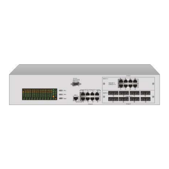
Introduction Unit Overview Front Panel Layout The front panel features the Front Panel Display, Panel Keys and ports. Figure 1.6 Ethernet Switch Front Panel Front Panel Display The Front Panel Display includes a high definition display and the Panel Keys that enable users to easily monitor and configure the system. The Front Panel Display provides diagnostic functions that include port settings, status monitoring, traffic utilization, collision and error rate. -
Page 13: Rear Panel Layout
Introduction or individually and monitor all switch settings. Rear Panel Layout The AC power socket is located on the rear panel. Figure 1.8 Rear Panel... -
Page 14: Chapter 2 Installation
Chapter Installation This chapter will provide you with detailed information on how to rack-mount the Switch, quickly set the Switch up and offer some connectivity suggestions. -
Page 15: Rack Mounting
Installation C h a p t e r 2 Installation Rack Mounting Rack mounting brackets are provided to mount the Switch in standard EIA 19-inch racks. Align the mounting brackets on the sides of the unit with the slit over the holes. -
Page 16: Installing Optional Modules
Installation Installing Optional Modules Power down Switch before installing an optional module. No hardware or software configuration settings are required. Please read this section carefully before installing modules. To install an option module, perform the following steps. Note: Modules are not hot-swapable. You must remove power from the switch before installing or replacing a module. -
Page 17: Quick Configuration
Installation Figure 2.3 Insert the Module Turn the two knobs on the new module until they are securely attached to the Switch. Connect AC power to the switch. Connect the appropriate communication cable to the new module. Quick Configuration Three basic parameters must be set in order to configure the Switch into your network. -
Page 18: Front Panel Display Configuration
Installation Front Panel Display Configuration Using the Front Panel Display Keys Prev: Scroll backward through menu items Menu Next: Scroll forward through menu items Selection Enter: Enter selected menu item Prev: Scroll through digits (0-9, -) Digit Next: Select current digit and move to next digit Input Enter: Enter selected string of digits Prev: Scroll backward through menu items... - Page 19 Installation Figure 2.4 The Main Menu Items Configuring the Basic Parameters 1. Enter UNIT CONFIG menu Unlock 2. Enter password digit "0000" 3. You will briefly see the PASSED message 1. Enter NETWORK CONF menu 2. Enter IP ADDRESS menu Configure 3.
-
Page 20: Console Management Configuration
Installation Console Management Configuration To start using the Console Management program, first connect an EIA-232 serial cable to a COM port on a PC or notebook computer and to the Console Port on the front panel of the Switch. Note: do not us a null modem cable. Terminal Program Baud: 9600 Parity: None... -
Page 21: Console Screens
Installation Console Screens In the Login Screen, you must enter a User Name and Password. The factory default User name is "admin" and the Password and empty string (i.e. you do not need to enter a Password). Figure 2.5 Login Screen... - Page 22 Installation If you are booting the Switch for the first time, you will first see the POST Download Screen as shown below. This screen allows you to set basic Switch configurations. Figure 2.6 POST Download Screen After the settings are configured, you must restart the Switch. Select REBOOT in the lower right hand side of the menu to reboot.
-
Page 23: Connecting Network Devices
2-10 Installation Connecting Network Devices This section provides you with some connectivity options. Connecting Fast Ethernet Hubs The example on page 2-11 shows how 10/100 Mbps hubs can be connected to the Switch to form a larger network. - Page 24 Installation 2-11 Figure 2.7 Connecting Fast Ethernet Hubs...
-
Page 25: Connecting Workstations
2-12 Installation Connecting Workstations This example shows the Switch directly connected to workstations. Figure 2.8 Connecting Workstations... -
Page 26: Connecting Fiber Ports
Installation 2-13 Connecting Fiber Ports This example shows how the fiber modules can be used for long distance connections. Figure 2.9 Connecting Fiber Ports... -
Page 27: Connecting Gigabit Devices
2-14 Installation Connecting Gigabit Devices This example shows how the Gigabit module can be used as a backbone connection. Figure 2.10 A Gigabit Backbone Connection... -
Page 28: Chapter 3 Front Panel Display Management
Chapter Front Panel Display Management This chapter will provide you with complete information about t he Front Panel Display. We will start with an overview of the interface, then take you through all of the menus and settings. -
Page 29: User Interface
Front Panel Display Management C h a p t e r 3 Front Panel Display Management User Interface The Front Panel Display is shown in Figure 3.1. It provides you with network management at your finger tip and allows you to observe real-time traffic and collision levels at a glance. -
Page 30: Front Panel Display Key Usage
Front Panel Display Management Item Indicates Percentage of utilization or collision Port Indicators Port status information. Please see Observing Basic Port Information on page 3-7 for more information. Port Indicator Frame Port status information. Please see Observing Basic Port Information on page 3-7 for more information. Bar Gauges Utilization levels, collision levels, status and setting information depending upon the current menu... -
Page 31: Front Panel Display Main Menu Circle
Front Panel Display Management Front Panel Display Main Menu Circle Figure 3.2 shows the Front Panel Display main menu structure. You can scroll forward or backward through the main menu items by pressing the Prev or Next keys. Enter menu items by pressing the Enter key. For a detailed listing of the main menu items and all of their sub-menus, please see the section titled Menu Tree on page 3-9 or Appendix B, Menu Tree. -
Page 32: Port Group Indicators
Front Panel Display Management Message Zone Figure 3.3 Message Zone Port Group Indicators On the right-hand side of the bar gauges, there are four port group indicators as shown in Figure 3.4. Depending on how many optional modules you install, there can be up to three port group indicators available: G-A (port group A), G-B (port group B) and G-C (port group C). - Page 33 Front Panel Display Management Port Group Indicators (Group B Selected) Figure 3.4 Port Group Indicators When the port group G-A icon is illuminated the Front Panel Display port indicators 1 through 8 represent the permanent switch ports 1 through 8 as shown in Figure 3.5.
-
Page 34: Observing Basic Port Information
Front Panel Display Management Observing Basic Port Information The basic port information, such as link up, link down, transmit/receive activity, enabled/disabled as well as auto partition can be easily monitored through the Port Indicators located in the first row of the Front Panel Display. -
Page 35: Port Indicator Definitions
Front Panel Display Management Port Indicator Definitions The following table summarizes the definition of the port indicators. Port Number Frame Indicates Dimly on Port enable, link down Port available, link up Flashing Link up, transmitting/receiving data Disabled by administrator Blinking Partitioned Table 3.3 Port Indicators... -
Page 36: Menu Tree
Front Panel Display Management Menu Tree There are up to four levels in the Menu Tree, main menu, sub-menu and up to two parameter option levels. To move from a main menu item to its sub menus, press the Enter console key while the main menu item is displayed in the Message Zone. - Page 37 3-10 Front Panel Display Management Main Menu Sub Menu Parameter Parameter UTILIZATION (G-A / G-B / G-C) COLLISION (G-A / G-B / G-C) SELECT GRP GROUP A GROUP B GROUP C MAIN MENU STATISTICS PORT 1 RX FRAMES Through RX OCTETS PORT X RX-ALIGN ERR RX-PKT ERR...
- Page 38 Front Panel Display Management 3-11 Main Menu Sub Menu Parameter Parameter PORT SETTING PORT 1 10BASE-T Through 100BASE-X PORT X 1000BASE-SX *AUTO-NEGO HALF DUPLEX FULL DUPLEX *ENABLED DISABLED BACK MAIN MENU MAIN MENU UNIT CONFIG LOOP DETECT ENABLED *DISABLED BACK MAIN MENU CONSOLE ENABLED...
-
Page 39: Exiting The Menu Tree
3-12 Front Panel Display Management Exiting the Menu Tree To exit a sub-menu, cycle through each menu option until a “MAIN MENU” or “BACK” is displayed in the Message Zone. Press the Enter key to return to the Main Menu or previous menu level. Utilization Monitoring the traffic load is accomplished by simply selecting a port group and then UTILIZATION from the main menu. - Page 40 Front Panel Display Management 3-13 Figure 3.7 Utilization for Group A Ports Press Enter to switch between the port groups. The port group indicators on the right hand side of the Front Panel Display indicate the port group that you select to view. Figure 3.7 and Figure 3.8 illustrate the utilization of port group A and port group B respectively.
-
Page 41: Collision
3-14 Front Panel Display Management Port Frame Indicates Number Dimly on Port enable, link down Port available, link up Flashing Link up, transmitting/receiving data Disabled by administrator Blinking Partitioned Table 3.6 Port Indicators Collision When COLLISION is the menu item in the Message Zone, the Port Number will be illuminated for each port that is connected and the bar gauges continuously move up or down indicating the percentage of Collision for these ports. -
Page 42: Select Group
Front Panel Display Management 3-15 Select Group There are three possible groups in the Switch, group A, B, and C. The 8 built- in ports are represented by group A. Groups B and C represent the optional modules' ports. When no modules are installed on the switch, there is only one group (group A). -
Page 43: Statistics
3-16 Front Panel Display Management Figure 3.11 Select Port Group A Press Prev and Next to scroll the port groups back and forth. Press Enter to make a selection as shown in Figure 3.12. Figure 3.12 Select Port Group B Statistics The STATISTICS menu displays the statistic counters of ports. - Page 44 Front Panel Display Management 3-17 Press Next in the MAIN MENU to select STATISTICS. Figure 3.13 Statistics Main Menu Press Enter to go to the port selection menu. The port selection menu allows users to select a port in the current port group for monitoring statistics counters.
- Page 45 3-18 Front Panel Display Management Figure 3.15 Selecting Port 7 in Group A Press Enter to make a port selection. The counter selection menu will then be displayed as shown in Figure 3.16. Figure 3.16 Counter Selection Menu Press Prev and Next to scroll back and forth through the statistics counter options.
-
Page 46: Statistics Counters
Front Panel Display Management 3-19 Figure 3.17 Readable Frames Counter Statistics Counters The available statistics counters are listed in Table 3.7. -
Page 47: Port Status
3-20 Front Panel Display Management RX FRAMES Displays the total number of good packets received including: Unicast packets Broadcast packets Multicast packets RX OCTETS To display the count of data and padding octets in frames that were successfully received. RX--ALIGN Displays the number of alignment errors. -
Page 48: Status Indicators
Front Panel Display Management 3-21 are displayed higher indicate the port is configured to the setting displayed in the message Zone. The shorter bar scales under the port numbers indicate the port is not set to the setting displayed in the message zone. All ports can be running at the same or different settings. -
Page 49: All Ports Status
3-22 Front Panel Display Management • DISABLED All Ports Status Press Next to select ALL PORTS in the port selection menu as shown in Figure 3.19. Figure 3.19 Selecting All Ports Press Enter to view the status for all ports as shown in the example in Figure 3.20. -
Page 50: Single Port Status
Front Panel Display Management 3-23 Single Port Status Press Next to select a single port in the port selection menu as shown in Figure 3.21. Figure 3.21 Selecting Port 7 Press Enter to view the status for the port as shown in the example in Figure 3.22. -
Page 51: Port Setting
3-24 Front Panel Display Management Port Setting The PORT SETTING menu is used to configure individual ports. This section will explore several aspects concerning the port setting menu. Auto-Negotiation All Switch ports support auto-negotiation. Auto-negotiation is the default setting for all ports. In auto-negotiation mode, the switch learns the settings of the link partner and configures itself to the highest possible transfer rate settings provided that the link partner also supports auto-negotiation. -
Page 52: Port Setting Options
Front Panel Display Management 3-25 SETTING menu. When you see an item that begins with an ‘*’, the port is set in that mode. All settings will be saved in the EEPROM. Port Setting Options Users may perform the following port settings: •... -
Page 53: User Authentication
3-26 Front Panel Display Management User Authentication To configure a port, user authentication is required when the system is locked. The user will be prompted to enter the password. The password is composed of four numeric digits represented by the four asterisks as shown in Figure 3.24. - Page 54 Front Panel Display Management 3-27 Figure 3.25 Selecting Port 7 Press Enter to view the setting options as shown in the example in Figure 3.26. Figure 3.26 Configuring a Port -- Before Setting Press Prev or Next to scroll through the setting options. Press Enter once the desired setting is found to apply the configuration to the port as shown in Figure 3.27.
-
Page 55: Unit Configuration
3-28 Front Panel Display Management Figure 3.27 Configuring a Port -- After Setting Unit Configuration The UNIT CONFIG menu shown in Figure 3.28 allows users to configure the switch as a whole. Press Prev or Next in the MAIN MENU to select UNIT CONFIG. Figure 3.28 Unit Configuration Main Menu To configure the switch, user authentication is required. -
Page 56: Unit Configuration Options
Front Panel Display Management 3-29 Unit Configuration Options Users may perform the following configurations to the device: • LOOP DETECT • CONSOLE LOCK • NETWORK CONFIGURATION • IP ADDRESS • SUBNET MASK • DEFAULT GATEWAY • SET PASSWORD • SYSTEM RESTART •... -
Page 57: Loop Detect
3-30 Front Panel Display Management Press Next to select next asterisk. Press Prev to select the next digit. Repeat to enter the password. Press Enter. You will briefly see the PASSED message if the password is correct and the system will be unlocked. If the password is incorrect, FAIL will be displayed, and the user will have to re-enter the password. -
Page 58: Console Lock
Front Panel Display Management 3-31 Console Lock The CONSOLE LOCK menu shown in Figure 3.30 allows users enable or disable the Front Panel Display configuration lock. Press Prev or Next in the UNIT CONFIG MENU to select CONSOLE LOCK. Figure 3.30 Console Lock Menu The Console Lock prevents unauthorized persons from making configuration settings to the Switch. -
Page 59: Unlock The Console
3-32 Front Panel Display Management Figure 3.31 Set Console Lock (before setting) Press Enter to enable the lock. When the device is locked, a lock sign and an asterisk will be displayed on the Front Panel Display as shown in Figure 3.32. -
Page 60: Network Configuration
Front Panel Display Management 3-33 Network Configuration The NETWORK CONF menu, as shown in Figure 3.33, contains the three parameters that allow you to configure the Switch on your network. Figure 3.33 Network Configuration Menu Network Configuration Options Users may perform the following Network Configuration options: •... -
Page 61: Ip Address
3-34 Front Panel Display Management IP Address Press Prev or Next in the NETWORK CONF menu to select IP ADDRESS as shown in the example in Figure 3.34. Figure 3.34 Selecting IP ADDRESS Press Enter. You will now see the IP ADDRESS menu as shown in Figure 3.35. -
Page 62: Subnet Mask
Front Panel Display Management 3-35 Press Next to select SYS RESTART. Press Enter. You will see SYS REBOOT. Press Enter to restart the Switch. The reboot will take several moments. The Switch is now configured in your network. Subnet Mask Setting the Subnet Mask involves the same process as setting the IP address. -
Page 63: System Restart
3-36 Front Panel Display Management Figure 3.36 Set Password Menu Press Enter. You will see the SET PASSWORD menu as shown in Figure 3.36. Press Prev once to select the first digit. Press Next to select next asterisk. Press Prev to select the next digit. Repeat to enter the new password. Press Enter. -
Page 64: System Default
Front Panel Display Management 3-37 Figure 3.37 System Restart Menu Press Enter in the SYS RESTART menu to perform a warm restart. You will see SYS REBOOT in the message zone for a few moments while the Switch is rebooting. System Default The system default menu shown in Figure 3.38, allows users to reset the device to the original factory configuration. -
Page 65: System Information
3-38 Front Panel Display Management System Information The SYSTEM INFO menu shown in Figure 3.39 allows users to view system information. Press Prev or Next in the MAIN MENU to select SYSTEM INFO. Figure 3.39 System Information Menu Press Enter to view system information. The following system information is automatically displayed in the message zone: •... - Page 66 Chapter Setting-Up for Console Management In this chapter, you will learn how to configure your Switch for management through the terminal emulation program.
-
Page 67: Chapter 4 Setting-Up For Console Management
Setting-Up for Console Management C h a p t e r 4 Setting-Up for Console Management Managing The Switch Several parameters of the Switch must be configured before you are able to access it via a Telnet session, the Web-Based Management interface or SNMP. -
Page 68: Setting-Up The Terminal Program
Setting-Up for Console Management Figure 4.1 Connecting a PC via Console Port. Note: Do not use a null modem cable. Setting-Up the Terminal Program A Terminal Program is required to communicate with The Switch’s internal software. An MSDOS based program such as PC-PLUS can make the connection with the device’s built-in software. - Page 69 Setting-Up for Console Management Windows95 provides a suitable program called HyperTerminal and is accessed from the Start menu. Click START, then Programs, Accessories and then HyperTerminal. Figure 4.2 Terminal Program. An MS -DOS type terminal program can also make the connection with the Switch’s built in software.
- Page 70 Setting-Up for Console Management Figure 4.3 Hypertrm.exe Icon The Connection Description Screen is displayed. Type a name in the Name panel to identify the connection, choose an icon (optional) and click OK. Figure 4.4 New Connection Screen. The following screen prompts for your country info, area code, telephone number and the modem type.
- Page 71 Setting-Up for Console Management Figure 4.5 Selecting a COM port. In the next screen all settings must be set correctly; Bits/sec “9600”, Data bits “8”, Parity “None”, Stop bits “1” and Flow Control “None” as in the figure below. Figure 4.6 Port Settings Click the OK button and the connection to the terminal program will be complete.
-
Page 72: Power On Self Test
Setting-Up for Console Management Power On Self Test When the Switch is powered up, the Power On Self Test, appears in the HyperTerminal window as shown in Figure 4.7. Figure 4.7 Power On Self Test As the Switch’s tests are run through, the test and their results will be displayed. -
Page 73: Navigating The Console Program Screens
Setting-Up for Console Management Navigating the Console Program Screens Use the following keyboard keys to navigate through the menu and select a sub-menu. These keyboard commands are common to all menus. TAB KEY: Use the TAB key to select screen menus. ENTER KEY: Press the ENTER key after selecting a menu item with the TAB key to view the selection’s sub-... -
Page 74: Login Screen
Setting-Up for Console Management Login Screen The Login Screen appears as show in Figure 4.9. If there is no text in the Hyper Terminal screen at this point, press Enter a few times and the Login Screen will appear. Figure 4.9 The Login Screen User Name and Password The factory default user name is "admin". -
Page 75: Main Menu
4-10 Setting-Up for Console Management Note that if you enter the user name or password incorrectly, when you press Enter, the field highlight will scroll back to User Name, and access will not be granted. Main Menu After passing through the login security screen, the Main Menu for console management is displayed as shown in Figure 4.10. -
Page 76: Post Download Menu
Setting-Up for Console Management 4-11 POST Download Menu The POST Download Menu will appear as shown in Figure 4.11 under the following circumstances: • When there is no valid system firmware in the Switch's flash memory • When a TFTP download operation fails •... -
Page 77: Tftp Server Ip Address
4-12 Setting-Up for Console Management TFTP Server IP Address If you want to download system software from a TFTP server, enter the TFTP server IP address in this field. Network Configuration Use the tab key to highlight IP Address listed under the heading New. Enter the IP address for the switch. - Page 78 Setting-Up for Console Management 4-13 • SAVE Saves changes to this screen without exiting. • REBOOT Reboots the switch, thus configuring all Network Configuration changes and executes all selected software downloads.
-
Page 79: Chapter 5 Console Management
Chapter Console Management This chapter will provide you with complete information on using the powerful console management interface. -
Page 80: Introduction
Console Management C h a p t e r 5 Console Management Introduction Console Management is used to manage the switch. It runs from a terminal program on a computer connected to the switch’s Console port via an RS-232 cable. See Chapter 4, “Setting-Up for Management”, for information about using a terminal program. -
Page 81: Navigating The Console Program Screens
Console Management Navigating the Console Program Screens The Console management uses limited keyboard keys such a Tab, Enter, and Ctrl + “letter” combinations to execute its commands. A glossary of commands can be found in the Help menu. These command keys and their functions are described as: TAB KEY: Use the TAB key to select screen menus. -
Page 82: User Name And Password
Console Management Figure 5.1 Login Screen User Name and Password The factory default user name is "admin". The factory default password is an empty string (i.e. you do not need to enter anything into the Password field). After entering the user name and pressing Enter in the password field, the main menu will appear. -
Page 83: Main Menu
Console Management Main Menu The Main Menu consists of five sub-menus, grouping different system configuration topics. Figure 5.2 Main Menu Help Menu Selecting HELP at the bottom of the menu screens and pressing Enter accesses the Help Menu. The help menu will appear as shown in Figure 5.3. -
Page 84: System Information
Console Management Figure 5.3 Help Menu System Information The Main Menu item, System Information, is shown in Figure 5.4. - Page 85 Console Management Figure 5.4 System Information Menu The System Information Menu provides version identification of the systems built-in software, which may be useful in the-event of any future upgrades becoming available. It also provides you with common system information. The following information settings can be edited and saved to memory by users that login with Read/Write privileges.
-
Page 86: Management Setup
Console Management Management Setup The Main Menu item, Management Setup, has several sub-menus. The Management Setup Menu is shown in Figure 5.5. Figure 5.5 Management Setup Menu The Management Setup Menu has 5 sub-menus for Network configuration and for configuring the SNMP community and Trap community. -
Page 87: Network Configuration
Console Management Management Setup Network Configuration Set IP, Subnet Mask and Default Gateway address. Serial Port Configuration View management port (RS-232) configuration. SNMP Community Setup Configure community names and access. Trap Receiver Configure addresses to which trap messages will be sent. Management Capability Enable or Disable Web management. -
Page 88: Serial Port Configuration
5-10 Console Management The Network Configuration Menu is used to configure the IP Address, Subnet Mask and Default Gateway. Network Configuration Network Interface Indicates Ethernet as the management interface type Index Interface Type Indicates the current management interface type MAC Address Indicates the current MAC address IP Address Internet Protocol address, identifying the switch,... -
Page 89: Snmp Community Setup
Console Management 5-11 Figure 5.7 Serial Port Configuration Menu The Serial Port Configuration Menu displays the settings that are required for the terminal connection that allows the Switch to communicate with a computer via the console port connected by an RS-232 cable to a computer’s serial port. - Page 90 5-12 Console Management Figure 5.8 SNMP Community Setup Menu The SNMP (Simple Network Management Protocol) Community Setup is similar to setting up passwords and access rights for Console Management or Web-Based management. Up to six community names can be configured with access and status rights.
-
Page 91: Trap Receiver Menu
Console Management 5-13 Trap Receiver Menu The Management Setup Menu item, Trap Receiver, is shown in Figure 5.9. Figure 5.9 Trap Receiver Menu Trap messages will be sent to all entries that have an Active status. Entering their names, setting their IP addresses and enabling their Status configures the trap receivers. -
Page 92: Management Capability Setup
5-14 Console Management To add or edit a trap receiver, press the Tab key to select the desired field and make the appropriate entries. To save the information, highlight the SAVE command and press the Enter key. Management Capability Setup The Management Setup Menu item, Management Capability Setup, is shown in Figure 5.10. -
Page 93: Trap Filter Setup
Console Management 5-15 Trap Filter Setup The Management Setup Menu item, Trap Filter Setup, is shown in Figure 5.11. Figure 5.11 Trap Filter Setup Menu The Trap Filter Setup Menu allows you to control which traps are sent. To have a trap message sent when a trap event occurs, place an “X” before the function listed. -
Page 94: Device Control
5-16 Console Management Device Control The Main Menu item, Device Control, has several sub-menus. The Device Control Menu is shown in Figure 5.12. Figure 5.12 Device Control Menu The Device Control Menu is used to view and or configure the Switch and it's ports. -
Page 95: Switch Configuration
Console Management 5-17 Device Control Switch Configuration Set the monitoring port and aging time of the system Switch Port Configuration Name ports and set their status Permanent Address Configure the permanent address entry Configuration Spanning Tree Protocol Configure the Spanning Tree Protocol Configuration parameters and view STP status Spanning Tree Protocol Port... -
Page 96: Switch Port Configuration
5-18 Console Management The Switch Configuration Menu displays the settings of the switch and allows the configuration of several settings. Switch Configuration Menu Unit ID The unit ID of the Switch Operational States the operational status of the associated board H/W Ver. - Page 97 Console Management 5-19 Figure 5.14 Switch Port Configuration Overview Menu The Switch Port Configuration Overview Menu is used to observe current individual port status and select individual ports for configuration. Switch Port Configuration Overview Menu Unit ID The unit ID of the Switch Group ID Allows you to select a port group (1=G-A, 2=G-B, 3=G-C)
-
Page 98: Switch Port Configuration Menu
5-20 Console Management Switch Port Configuration Menu The Switch Port Configuration Menu is shown in Figure 5.15 Figure 5.15 Switch Port Configuration Menu The top of this screen describes the selected port. The left side of the screen displays the current port configuration. The fields on the right side allow you to configure new settings for the port. -
Page 99: Permanent Address Configuration
Console Management 5-21 Switch Port Configuration Menu Settings Unit ID The unit ID of the Switch. Port Number Specifies which port is displayed. You can enter a port number here and press the Enter key to select different ports. Interface Type The network interface type for the port. -
Page 100: Permanent Address Configuration Menu (View)
5-22 Console Management Permanent Address Configuration Menu (View) The first Permanent Address Configuration Menu for viewing current configurations is shown in Figure 5.16. Figure 5.16 Permanent Address Configuration Menu (View) The Permanent Address Configuration Menu displays current information on all permanent addresses currently stored in the Switch. To edit a permanent address, tab to select an Index number and press the Enter key. - Page 101 Console Management 5-23 Figure 5.17 Permanent Address Configuration Menu (Edit) Up to 128 permanent MAC addresses can be assigned in this menu. Once a MAC address is assigned to a port and the status is Active, the device associated with the MAC address can then only be connected to the assigned port.
-
Page 102: Spanning Tree Protocol Configuration
5-24 Console Management Spanning Tree Protocol Configuration The Device Control Menu item, Spanning Tree Protocol Configuration, is shown in Figure 5.18 Figure 5.18 Spanning Tree Protocol Configuration Menu This menu allows you to monitor and configure the switch’s STP system. The switch uses one STP system with a single MAC address. - Page 103 Console Management 5-25 • STP Max. Age The maximum age of STP information learned from the netwrok on any port before it is discarded. • STP Hello Time The amount of time between the tranmission of PDUs by this node on any port when it is the root of the spanning tree or trying to become so.
-
Page 104: Spanning Tree Protocol Port Configuration
5-26 Console Management Spanning Tree Protocol Port Configuration The Device Control Menu item, Spanning Tree Protocol Port Configuration, is shown in Figure 5.19. Figure 5.19 Spanning Tree Protocol Port Configuration Menu This menu allows you to monitor and configure the STP settings for each of the switch’s ports. -
Page 105: Port Statistics
Console Management 5-27 • STP Port Designated Root Read only. States the bridge identifier of the root bridge. • STP Port Designated Cost Read only. States the path cost of the designated port of the segment connected to the given port. •... - Page 106 5-28 Console Management Figure 5.20 Port Statistics Menu This menu allows you to monitor detailed statistics for each individual port. 32-bit counters are used and can display a counter value of up to 4,294,967,295. Port Statistics Counters: • Unit ID States the unit ID of the Switch. •...
-
Page 107: User Authentication
Console Management 5-29 • CRC Errors The total CRC or alignment error frames within the proper size (64-1518 octets) received by the port. • Undersize Frames The number of packets received that were less than 64 octets long. • Oversize Frames The number of packets received that were longer than 1536 octets. -
Page 108: User Authentication Menu (Edit)
5-30 Console Management Figure 5.21 User Authentication Menu The User Authentication Menu uses three screens in total to configure User Name and Password access to the Switch. The first screen provides read-only information and allows you to select a user index to add or edit. The second screen allows you to add or edit the selected user index. - Page 109 Console Management 5-31 Figure 5.22 User Authentication Menu (Edit) In this menu, a User Name of up to 12 alphanumeric characters and Password of up to 6 alphanumeric characters can be entered and its Read/Write privilege can be set. The defaults are: •...
-
Page 110: User Authentication Menu -2
5-32 Console Management A User Name and Password can also be deleted using the DELETE command. Select the EXIT command to return to the previous screen and view the results. User Authentication Menu -2- When the Front Panel Display Password is selected to edit, you will see the User Authentication Menu -2- as shown in Figure 5.23. -
Page 111: System Utility
Console Management 5-33 Select SAVE and press Enter to save the new Password. Select EXIT to return to the main User Authentication Menu. Note that the Front Panel Display Password cannot be deleted. System Utility The Main Menu item, System Utility, has several sub-menus. The System Utility Menu is shown in Figure 5.12. -
Page 112: System Restart
5-34 Console Management The System Utility Menu is used to perform system restarts, system downloads and several other system utility functions. The following is a brief overview of the System Utility sub-menus: System Utility System Restart Restart the Switch Factory Reset Reset to factory configuration Login Timeout Interval Specify the period of inactivity... -
Page 113: System Restart Menu (Confirm)
Console Management 5-35 Figure 5.25 System Restart Menu The System Restart function uses two menus to perform Switch restarts. The first menu allows you to select a cold or warm restart and the second menu prompts you to confirm the restart. Selecting "Cold Start"... -
Page 114: Factory Reset
5-36 Console Management Figure 5.26 System Restart Menu (Confirm) In the System Restart Menu (Confirm), press the Enter key to execute the selected system restart, or press the Esc key to cancel the restart and return to the first System Restart Menu. Factory Reset The System Utility Menu item, Factory Reset, is shown in Figure 5.27. - Page 115 Console Management 5-37 Figure 5.27 Factory Reset Menu The Factory Reset function uses two menus to perform Switch restarts. The first menu allows you to select which configurations you wish to reset and the second menu allows you to confirm the reset execution. The following section describes the Factory Reset Menu items and their options: •...
-
Page 116: Factory Reset Menu (Confirm)
5-38 Console Management management default user name is "admin". The factory default console management password is an empty string. • SNMP Community Configuration Resets the current SNMP Community Configuration settings. • Not Reset The current SNMP community configuration settings will not be reset. -
Page 117: Login Timeout
Console Management 5-39 In the Factory Reset Menu (Confirm), press the Enter key to execute the selected factory reset, or press the Esc key to cancel the restart and return to the first Factory Reset Menu. Login Timeout The System Utility Menu item, Login Timeout, is shown in Figure 5.29. Figure 5.29 Login Timeout Menu The Login Timeout Menu allows you to set the amount of time an established console management session is inactive before it is automatically logged out. -
Page 118: System Download
5-40 Console Management Note that if you do not want a console management session to be automatically timed out, enter 0 into the field. System Download The System Utility Menu item, System Download, is shown in Figure 5.30 Figure 5.30 System Download Menu The System Download Menu allows you to view and set the parameters used in performing a TFTP download operation. -
Page 119: Executing A System Download
Console Management 5-41 If your network does not have a properly configured Bootp server, do not select Bootp Request. In this case, you can select Boot ROM Code Download to download boot ROM code from the software. To execute a download, you must enter the IP address of a remote computer that is TFTP server enabled in the TFTP Server IP Address field. - Page 120 5-42 Console Management Note: If the Login Screen text is unusual after a software download, simply disconnect and reconnect your terminal emulation program. 8. At this point, you should conduct a ping from the terminal you are using to ensure that the new software is configured properly. Note: If the ping is timed out, simply plug your Ethernet connection into a different port and conduct another ping.
-
Page 121: Technical Specifications
Technical Specifications A p p e n d i x A Technical Specifications Standard Compliance Switch Performance IEEE 802.3 10BASE-T Ethernet RAM buffer: 128K per port IEEE 802.3u 100BASE-TX/FX Fast Packet filtering/forwarding rate Ethernet 100Mbps - 148,800 pps IEEE802.3z 1000BASE-SX Ethernet 10Mbps - 14,880 pps Number of Ports MAC address learning capability: Up to... - Page 122 Technical Specifications Configuration data held in nonvolatile Password, Console Lock Enable, System storage Restart, System Default, System Information display Flow Control for each port Power Requirements Self-diagnostics Power On Self Test 100-240 VAC, 50/60 Hz / 80W internal universal power supply Web-Based Management Environment Management from anywhere and any...
- Page 123 Menu Tree A p p e n d i x B Menu Tree...
- Page 124 Menu Tree...
- Page 125 Glossary A p p e n d i x C Glossary 100BASE-FX A variant of IEEE 802.3 for a 100Mbps Ethernet-like network. Borrows the physical characteristics of FDDI's multimode fiber PMD, but uses Ethernet framing & CSMA/CD. 100BASE-T Generic name for the 100Mbps vairants of IEEE 802.3, especially the twisted-pair based ones.
- Page 126 Glossary ThinWire Ethernet (IEEE 802.3 10BASE2) uses BNC connectors. Bridge A network "relay" which reads, buffers and sends data to relay it from one data link to another. A bridge makes the two connected data links appear as one link to all higher data link layer levels. Broadcast A message (e.g.
- Page 127 Glossary CSMA/CD "Carrier Sense Multiple Access with Collision Detection" The method by which nodes on an Ethernet/IEEE 802.3 LAN gain access to the network, i.e. one of several techniques that have been built into different LAN technologies to allow multiple nodes to share the same wires/electronics to send their data.
- Page 128 Glossary Frame A term for the unit of data transferred on a LAN. Depending on the type of LAN, it can be hundreds or thousands of bytes long (any particular type of LAN will have a limit on the frame size, e.g. Ethernet's 1500 byte/octet limit).
- Page 129 Glossary IP "Internet Protocol" The basic protocol of TCP/IP and the Internet. Novell's protocol used by Netware. Utilizes part of XNS. A router with "IPX routing" purports to interconnect LANs so that Novell Netware clients & servers can talk through the router. LAN Switching Term for bridging or cut-through switching, usually referring to a device with more than two ports.
- Page 130 Glossary POP "Post Office Protocol" A TCP/IP-based protocol designed to allow client-stations (e.g. micros) to read mail from a server. There are three versions under the name "POP": POP, POP2, and POP3. Latter versions are NOT compatible with earlier versions. Protocol The "rules"...
- Page 131 Glossary (see "POP") are often used in that context. However, servers will use SMTP if they need to transfer a message to another server. SNMP "Simple Network Management Protocol" Originally developed to manage IP based network equipment like routers and bridges, now extended to wiring hubs, workstations, toasters, jukeboxes, etc.
- Page 132 Glossary Pair"). UTP (Unshielded Twisted-Pair) See "Twisted-Pair" and "Shielded Twisted-Pair". Virtual LAN (VLAN) A portion of one or more LAN switches which delivers packets as if it were a physical LAN; actually like a switched LAN. The most primitive VLAN facility that a switch can have allows the switch to be partitioned into two or more groups of ports (VLANs) within which communication is possible, but between which communication is blocked.
- Page 133 Index A p p e n d i x D Index About the Switch, 1-2 Permanent Address Configuration, Front Panel Display Highlights, 1- 5-21 Permanent Address Configuration Key Features, 1-3 Permanent Address Collision, 3-14 Configuration Menu (Edit), Connecting Fast Ethernet Hubs, 2-10 5-22 Connecting Fiber Ports, 2-13 Permanent Address...
- Page 134 Index Trap Receiver Menu, 5-13 Navigating the Console Program User Authentication Screens, 4-8, 5-3 User Authentication Menu Network Configuration, 5-9 (Edit), 5-30 Network Configuration, 3-33 User Authentication Menu -2-, Configuring the Parameters, 3-33 5-32 Default Gateway, 3-35 User Authentication, 5-29 IP Address, 3-34 User Name and Password, 5-4 Network Configuration Options, 3-...
- Page 135 Index Rear Panel Layout, 1-7 Hardware Version, 3-38 Select Group, 3-15 IP Address, 3-38 Serial Port Configuration, 5-10 Software Version, 3-38 Set Password, 3-35 Subnet Mask, 3-38 Setting-Up for Management, 4-2 System Restart, 5-34 Console Program, 4-2 System Restart, 3-36 Login Screen, 4-9 System Utility, 5-33 Main Menu, 4-10...
Need help?
Do you have a question about the GSW-0800TXM and is the answer not in the manual?
Questions and answers