HP ProLiant DL580 Setup And Installation Manual
Generation 2 server
Hide thumbs
Also See for ProLiant DL580:
- User manual (139 pages) ,
- Maintenance and service manual (137 pages) ,
- Quickspecs (56 pages)

Related Manuals for HP ProLiant DL580


Summary of Contents for HP ProLiant DL580
- Page 1 HP ProLiant DL580 Generation 2 Server Setup and Installation Guide May 2003 (Third Edition) Part Number 230835-003...
- Page 2 The information in this document is provided “as is” without warranty of any kind and is subject to change without notice. The warranties for HP products are set forth in the express limited warranty statements accompanying such products. Nothing herein should be construed as constituting an additional warranty.
-
Page 3: Table Of Contents
Processors ......................... 1-5 Memory........................1-5 PCI-X Expansion Slots ..................... 1-7 Network Interface Controller ..................1-7 System Health Indicators ..................1-8 Integrated Lights-Out....................1-9 SCSI Support ......................1-10 Storage and Media Drives..................1-12 HP ProLiant DL580 Generation 2 Server Setup and Installation Guide... - Page 4 Overview of Controller Features ..................3-1 Battery-Backed Write Cache Enabler ................3-3 Memory..........................3-4 Controller Interface......................3-4 Drive Array Technology ....................3-4 Fault Management Features.....................3-5 Chapter 4 Planning the Server Installation Optimum Environment ....................4-2 Space and Airflow Requirements................4-2 HP ProLiant DL580 Generation 2 Server Setup and Installation Guide...
- Page 5 Replacing a Hot-Plug Fan..................5-43 Hot-Plug Power Supplies ....................5-44 Locating the Power Supplies .................. 5-44 Removing a Redundant Hot-Plug Power Supply or Blank........5-45 Installing a Redundant Hot-Plug Power Supply ............. 5-46 HP ProLiant DL580 Generation 2 Server Setup and Installation Guide...
- Page 6 Hot-Plug PCI-X Expansion Slot LEDs ..............7-6 Performing PCI-X Hot Plug Operations ................7-9 Removing a PCI-X Hot Plug Expansion Board ............7-10 Installing or Replacing a PCI-X Hot Plug Expansion Board ........7-12 Installing a Non-Hot-Plug Expansion Board............7-17 HP ProLiant DL580 Generation 2 Server Setup and Installation Guide...
- Page 7 Registering the Server ..................... 9-3 Routine Maintenance....................... 9-3 Chapter 10 Server Configuration and Utilities ROM-Based Setup Utility ..................... 10-2 Navigating RBSU ....................10-2 Saving RBSU Configuration Settings..............10-3 Using RBSU ......................10-3 HP ProLiant DL580 Generation 2 Server Setup and Installation Guide...
- Page 8 Class B Equipment ....................A-4 European Union Notice ....................A-5 Japanese Notice....................... A-5 BSMI Notice ........................A-6 Laser Devices........................A-6 Laser Safety Warnings ..................... A-6 Compliance with CDRH Regulations ..............A-6 viii HP ProLiant DL580 Generation 2 Server Setup and Installation Guide...
- Page 9 Memory Board LEDs ......................E-9 Battery-Backed Write Cache Enabler ................E-13 QuickFind Diagnostic Display ..................E-15 System Board Switches ....................E-16 System Maintenance Switch (SW4) ...............E-17 System ID switch (SW7) ..................E-20 iLO/Spread Spectrum Switch (SW8)..............E-21 HP ProLiant DL580 Generation 2 Server Setup and Installation Guide...
- Page 10 HP ProLiant DL580 Generation 2 server ..............1-2 iLO Standard management port on the rear panel.............2-3 iLO Standard Security Override................2-6 ProLiant DL580 Generation 2 servers installed in a rack .........4-1 Rack-mounting hardware ..................4-8 Removing the shipping bracket .................4-9 Front panel components ....................5-5 Rear panel components .....................5-6...
- Page 11 Installing the BBWCE .................... 5-51 5-46 Connecting the cable to the BBWCE..............5-52 Memory board......................6-3 Memory board LEDs ....................6-4 Memory board slots ....................6-8 Removing the memory board.................. 6-21 HP ProLiant DL580 Generation 2 Server Setup and Installation Guide...
- Page 12 Attaching the cable management arm to the round-hole rack .........8-21 8-18 Sliding the server forward in the rack ..............8-22 8-19 Attaching the cable management arm to the server..........8-22 8-20 Aligning the cable management arm pivot points...........8-23 HP ProLiant DL580 Generation 2 Server Setup and Installation Guide...
- Page 13 Slimline Drive Bays....................5-38 Hot-Plug Fans ......................5-41 Power Supplies ....................... 5-44 Battery-Backed Write Cache Enabler ..............5-49 Parts of the Memory Board..................6-3 Advanced ECC (Standard) Memory Mode............... 6-4 HP ProLiant DL580 Generation 2 Server Setup and Installation Guide xiii...
- Page 14 Is the External Health LED Green?................H-8 Is the Internal Health LED Green?................H-9 Is the Monitor Displaying Information?..............H-11 Problems After Initial Boot ..................H-12 Troubleshooting Resources ..................H-16 HP ProLiant DL580 Generation 2 Server Setup and Installation Guide...
-
Page 15: About This Guide
DL580 Generation 2 servers. Audience Assumptions This guide is for the person who installs, administers, and troubleshoots servers. HP assumes you are qualified in the servicing of computer equipment and trained in recognizing hazards in products with hazardous energy levels. - Page 16 WARNING: To reduce the risk of personal injury or damage to the Weight in kg equipment, observe local occupational health and safety requirements Weight in lb and guidelines for manual material handling. HP ProLiant DL580 Generation 2 Server Setup and Installation Guide...
-
Page 17: Rack Stability
IMPORTANT: Text set off in this manner presents essential information to explain a concept or complete a task. NOTE: Text set off in this manner presents additional information to emphasize or supplement important points of the main text. HP ProLiant DL580 Generation 2 Server Setup and Installation Guide xvii... -
Page 18: Related Documents
Technical Support In North America, call the HP Technical Support Phone Center at 1-800-652-6672. This service is available 24 hours a day, 7 days a week. For continuous quality improvement, calls may be recorded or monitored. Outside North America, call the nearest HP Technical Support Phone Center. -
Page 19: Hp Website
Third-party hardware or software • Operating system type and revision level HP Website The HP website has information on this product as well as the latest drivers and flash ROM images. You can access the HP website at www.hp.com Authorized Reseller For the name of the nearest authorized reseller: •... -
Page 20: Optional Installation Service
About This Guide Optional Installation Service You may choose to have HP install the system. The installation service can be purchased as an HP Care Pack packaged service or as a customized service agreement to meet your specific requirements. Some of the HP Care Pack services are as follows: •... -
Page 21: Server Features
Server Features The HP ProLiant DL580 Generation 2 server is the ideal solution for enterprise customers who require a rack optimized, four-way server that delivers maximum performance and availability for highly complex, business-critical applications. Maximum performance levels are achieved through superior engineering design and the use of such industry-standard technologies as: •... -
Page 22: Hp Proliant Dl580 Generation 2 Server
New rapid deployment rack rails • Efficient and space-saving dense form factor [4U is 17.8-cm (7-in) high] This chapter provides an overview of the HP ProLiant DL580 Generation 2 server features and briefly describes its maximum performance, high availability, server management, and serviceability features. -
Page 23: Overview
• PCI-X Hot Plug • Redundant ROM • Optional redundant NIC The ProLiant DL580 Generation 2 server offers a highly scalable environment with the following expansion capabilities: • Memory expansion to 32 GB • Four SCSI hard drive bays •... - Page 24 Automatic Server Recovery-2 (ASR-2) • Integrated Management Log (IML) • Pre-Failure Warranty on hard drives, processors, and memory The ProLiant DL580 Generation 2 server also features ease-of-use components such • Toolless serviceable chassis • Toolless mountable sliding rack rails •...
-
Page 25: Standard Features
Specifically, integrated Level 3 cache, which is only available on the Xeon Processor MP, provides a high-bandwidth path to memory, increasing throughput for large server workloads. The ProLiant DL580 Generation 2 server features the following advanced processor technologies: •... - Page 26 — Online spare memory — Single-board mirrored memory — Dual board hot-plug mirrored memory — Hot-Add functionality For more information on Hot-Add functionality, refer to the HP ProLiant DL580 Generation 2 and HP ProLiant ML570 Generation 2 Server Hot-Add Memory booklet on www.hp.com For more information on Advanced Memory Protection, refer to Chapter 6, “Memory.”...
-
Page 27: Pci-X Expansion Slots
Server Features PCI-X Expansion Slots The ProLiant DL580 Generation 2 server offers four 64-bit, 100-MHz, peered PCI-X buses that ensure optimal availability and performance. The server provides support for six expansion slots (3.3V keyed)—four hot-plug slots and two non-hot-plug slots. -
Page 28: System Health Indicators
Network fault tolerance System Health Indicators The ProLiant DL580 Generation 2 server contains several sets of LEDs that indicate the status of hardware components and settings. A new feature is the QuickFind Diagnostic Display. These LEDs, located on the front access panel, enable you to quickly diagnose a problem with a component in the server simply by referring to the access panel. -
Page 29: Integrated Lights-Out
Lights-Out functionality. The iLO Standard is provided as standard on all ProLiant DL580 Generation 2 servers. The iLO features include: • iLO is built into every ProLiant DL580 Generation 2 server; no slot is needed. • iLO is easy to setup and easy to use. •... -
Page 30: Scsi Support
PKI support (future support) SCSI Support The ProLiant DL580 Generation 2 server provides support for both internal and external SCSI devices. The ProLiant DL580 Generation 2 server ships with an internal four-bay drive cage. The cage supports Ultra3/Ultra4 SCSI hot-plug hard drives. - Page 31 — Fully transportable to another ProLiant DL580 Generation 2 server in the data center NOTE: In order to easily transport protected cache data to another ProLiant DL580 Generation 2 server, remove the BBWCE and the 5i Plus Memory Module simultaneously.
-
Page 32: Storage And Media Drives
Server Features Storage and Media Drives The ProLiant DL580 Generation 2 server offers slimline drive bays for flexibility in storage and media drives. For more information about installing storage and media drives into the slimline drive bays, refer to Chapter 5, “Installing Hardware Options.”... -
Page 33: Hot-Plug Power Supplies
Auto Line Sensing capability automatically selects the appropriate line voltage. • Power Down Manager ensures that ProLiant DL580 Generation 2 servers deactivate in a manner that safeguards data and system integrity. HP ProLiant DL580 Generation 2 Server Setup and Installation Guide... -
Page 34: Standard Interfaces
Server Features Standard Interfaces The ProLiant DL580 Generation 2 server is equipped with the following standard interfaces: • Serial connector • Video connector • Keyboard connector • Mouse connector • Two USB connectors located at the rear of the server •... -
Page 35: Server Configuration And Management
Server Features Server Configuration and Management HP offers an extensive set of features and optional tools to support effective server configuration and management. This section provides an overview of the following server management features that are detailed in Chapter 10, “Server Configuration and Utilities.”... - Page 36 Remote ROM Flash Utility The Remote ROM Flash Utility enables administrators to upgrade the system ROMs as well as the supported HP Smart Array controllers on multiple servers from a single point of execution. The ROM upgrades can be flashed either individually or batched together to perform multiple ROM upgrades in a single step.
-
Page 37: Software Tools And Utilities
HTTP, SNMP, MIB2, or DMI v2.0-compliant device. Insight Manager 7 is installed from the Management CD. It is an easy-to-use, intuitive software utility designed for collecting server information including fault conditions, performance, security, remote management, and recovery services. HP ProLiant DL580 Generation 2 Server Setup and Installation Guide 1-17... -
Page 38: Security Features
The IML provides a detailed log of key system events. This log also monitors the server health log and is accessible from Insight Manager 7 and the Remote Insight Lights-Out Edition II (RILOE II) option. NOTE: The ProLiant DL580 Generation 2 server no longer supports the first-generation RILOE board option. •... -
Page 39: Diagnostic Tools
For additional information about server security features, refer to the Documentation CD and the ProLiant Essentials Foundation Pack that ships with the server. Diagnostic Tools The ProLiant DL580 Generation 2 server provides the following software and firmware diagnostic tools: • Power-On Self-Test (POST) •... -
Page 40: Warranties And Services
Under the global warranty, product warranty terms at the time of purchase are honored in any country where HP has a service presence. This applies to customers who may purchase a product in one country, then transfer it to another. -
Page 41: Pre-Failure Warranty
Server Registration Registering the server provides HP with valuable information on server installation. This information helps HP serve your needs better now and in the future. To register the server, refer to www.compaq.com/register... -
Page 42: Integrated Lights-Out
Integrated Lights-Out The ProLiant DL580 Generation 2 server includes the Integrated Lights-Out Standard (iLO Standard). The iLO Standard provides server health and remote server management. The server also supports the optional iLO Advanced feature. For additional information on iLO Advanced, refer to the documentation provided with the option kit. -
Page 43: Features
• Remote Firmware Update This feature ensures that iLO Standard is always up-to-date with the latest firmware available from HP. Updates to the ROM code on iLO Standard are accomplished through the browser interface. • Virtual Private Network (VPN) support When used in conjunction with VPN technology, iLO Standard functionality is available around the world. -
Page 44: Ilo Standard Management Port On The Rear Panel
The iLO Standard provides strong security for remote management in distributed IT environments. Secure Sockets Layer (SSL) encryption (up to 128-bits) ensures the HTTP information is secure as it travels across the network. HP ProLiant DL580 Generation 2 Server Setup and Installation Guide... - Page 45 The independent console of the operating system supports text and graphic modes, displaying remote host server activities, such as shutdown and startup operations. HP ProLiant DL580 Generation 2 Server Setup and Installation Guide...
- Page 46 — Deploy an operating system on remote servers from network drives — Perform disaster recovery of failed operating systems NOTE: Virtual graphical console and virtual media are optional on the ProLiant DL580 Generation 2 server. These advanced features can be licensed with the optional iLO Advanced Pack.
-
Page 47: Integrated Lights-Out Standard Security Override
3. Open the rear access panel. Refer to “Opening and Removing the Access Panels” in Chapter 5, “Installing Hardware Options.” 4. Locate the iLO Standard Security Override, and move the switch from the off position to the on position. HP ProLiant DL580 Generation 2 Server Setup and Installation Guide... - Page 48 In the unlikely event it is necessary, enabling the iLO Standard Security Override also enables the iLO Standard boot-block to be flashed. The boot-block is exposed until the iLO Standard is reset. HP recommends the iLO Standard be disconnected from the network until the reset is complete.
-
Page 49: Integration With Insight Manager 7
Configuration and Operation For specific information on configuring and operating iLO Standard, refer to the Integrated Lights-Out User Guide. HP ProLiant DL580 Generation 2 Server Setup and Installation Guide... -
Page 50: Smart Array 5I Plus Controller
Smart Array 5i Plus Controller The HP ProLiant DL580 Generation 2 server is equipped with the Smart Array 5i Plus Controller. The Smart Array 5i Plus Controller and BBWCE is a Wide Ultra3 SCSI hard drive array controller with a 64-MB read/write embedded cache and a battery-backed write enabler that provides transportable data protection and increases overall controller performance. - Page 51 — Pre-Failure Warranty and Pre-Failure Notification for HP drives (requires Insight Manager) — Easy-to-use Array Configuration Utility (ACU) and browser-based Array Configuration Utility XE (ACU-XE) — Option ROM Configuration for Arrays (ORCA) Utility — Redundant ROM HP ProLiant DL580 Generation 2 Server Setup and Installation Guide...
-
Page 52: Battery-Backed Write Cache Enabler
LED indicates the status of the data retention. Refer to “Battery-Backed Write Cache Enabler” in Appendix E, “System LEDs and Switches,” for more information. HP ProLiant DL580 Generation 2 Server Setup and Installation Guide... -
Page 53: Memory
You may set each logical drive in the array to a different fault-tolerant configuration. The Smart Array 5i Plus Controller and BBWCE manage the drive array independent of the host processor. HP ProLiant DL580 Generation 2 Server Setup and Installation Guide... -
Page 54: Fault Management Features
— Functional tests such as track-to-track, one-third stroke, and full-stroke time • Drive failure alert features cause an alert message to be displayed on the system monitor when drive failure occurs. Different server models use different messages for different situations. HP ProLiant DL580 Generation 2 Server Setup and Installation Guide... - Page 55 This feature allows you to take corrective action with minimal effect on critical business operations. The system must use Insight Manager and an HP Smart Array controller to benefit from predictive failure alert. Instructions for using the predictive failure alert feature can be found in the documentation for Insight Manager software and HP Management Agents.
-
Page 56: Planning The Server Installation
Planning the Server Installation This chapter provides information and instructions for planning the installation of the new HP ProLiant DL580 Generation 2 server. Figure 4-1 illustrates multiple ProLiant DL580 Generation 2 servers installed in a rack. Figure 4-1: ProLiant DL580 Generation 2 servers... -
Page 57: Optimum Environment
Leave a minimum clearance of 121.9 cm (48 in) from the back of the rack to the rear of another rack or row of racks. HP servers draw in cool air through the front door and expel warm air through the rear door. Therefore, the front and rear rack doors must be adequately ventilated to allow ambient room air to enter the cabinet, and the rear door must be adequately ventilated to enable the warm air to escape from the cabinet. -
Page 58: Temperature Requirements
NFPA 70, 1999 Edition (National Electric Code) and NFPA 75, 1992 Edition (code for Protection of Electronic Computer/Data Processing Equipment). For electrical power ratings on options, refer to the product rating label or the user documentation supplied with that option. HP ProLiant DL580 Generation 2 Server Setup and Installation Guide... -
Page 59: Grounding Requirements
Because of the high ground leakage currents associated with multiple servers connected to the same power source, HP recommends the use of a power distribution unit (PDU) that is either permanently wired to the branch circuit of the building or includes a nondetachable cord that is wired to an industrial-style plug. -
Page 60: Rack Planning Resources
The following resource information is available on rack designs and products. The Rack Builder Pro Configuration Tool and Rack Products documentation information can be found on the HP website by following the storage link on the product website. The entire Rack Resource CD Kit ships with all Compaq branded racks. A summary of the content of each CD follows: •... -
Page 61: Rack Warnings And Cautions
CAUTION: Always begin by mounting the heaviest item on the bottom of the rack. Continue to populate the rack from the bottom to the top. HP ProLiant DL580 Generation 2 Server Setup and Installation Guide... -
Page 62: Server Warnings And Cautions
ProLiant DL580 Generation 2 server • Hardware documentation, reference information, and software products • Power cords • Rack-mounting hardware Use Figure 4-2 and Table 4-1 to identify the rack-mounting hardware. HP ProLiant DL580 Generation 2 Server Setup and Installation Guide... -
Page 63: Rack-Mounting Hardware
Figure 4-2: Rack-mounting hardware Table 4-1: Rack-Mounting Hardware Item Description Item Description Rack rail assemblies (2) Rack template Server rails (2) Note: Cable management components are not shown in this illustration. HP ProLiant DL580 Generation 2 Server Setup and Installation Guide... -
Page 64: Removing Shipping Bracket From Pci Basket
To remove the shipping bracket from the PCI Basket, loosen the thumbscrew (1) and remove and discard the shipping bracket (2). Figure 4-3: Removing the shipping bracket NOTE: The shipping bracket is used only to secure the PCI Latches during shipment. HP ProLiant DL580 Generation 2 Server Setup and Installation Guide... -
Page 65: Installing Hardware Options
Installing Hardware Options This chapter explains procedures for the installation of hot-plug and non-hot-plug options specific to the HP ProLiant DL580 Generation 2 server. To streamline the installation process, read the installation instructions for all the hardware options and identify similar steps before installing the hardware options. If you encounter any problems during installation, contact an authorized reseller. - Page 66 CAUTION: Electrostatic discharge can damage electronic components. Be sure you are properly grounded before beginning any installation procedures. HP ProLiant DL580 Generation 2 Server Setup and Installation Guide...
-
Page 67: Additional Options And Procedures
Installing Hardware Options Additional Options and Procedures The ProLiant DL580 Generation 2 server supports several additional options not discussed in this chapter, including: • Rack Deployment Options The ProLiant DL580 Generation 2 server supports several rack-mounting options, including: — Telco rack mounting kit, which is a set of adjustable rack brackets that supports installation in telco racks. - Page 68 Redundant hot-plug power supplies • Memory board in the hot-plug mirrored memory mode or when Hot-Add functionality guidelines are met • PCI-X Hot Plug expansion boards, slots 3 through 6 HP ProLiant DL580 Generation 2 Server Setup and Installation Guide...
-
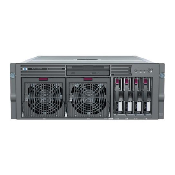
Page 69: Front Panel Components
Power On/Standby button and LED SCSI hot-plug hard drive bays 0 through 3 Primary hot-plug power supply Redundant hot-plug power supply Note: Power supplies are only redundant when both power supplies are installed. HP ProLiant DL580 Generation 2 Server Setup and Installation Guide... -
Page 70: Rear Panel Components
Rear Unit Identification button and LED Torx T-15 tool PCI-X Hot Plug slots 3 through 6 PCI-X non-hot-plug slots 1 and 2 (NIC is in slot 2) AC inlet (primary) AC inlet two (redundant) HP ProLiant DL580 Generation 2 Server Setup and Installation Guide... -
Page 71: Preparing For An Installation
4. Disconnect all power cords. 5. Disconnect any other external equipment connected to the computer. The system is now without power, and you can safely proceed with the installation of your hardware options. HP ProLiant DL580 Generation 2 Server Setup and Installation Guide... -
Page 72: Locating And Removing The Torx T-15 Tool
Installing Hardware Options WARNING: The system power in the ProLiant DL580 Generation 2 server does not shut off completely from the front panel Power On/Standby button. The two positions function as on and standby, rather than on and off. The standby position removes power from most of the electronics and the drives;... -
Page 73: Extending The Server From The Rack
To perform some installation procedures, you must extend the server from the rack. To extend the server from the rack: 1. Loosen the thumbscrews that secure the server to the front of the rack. Figure 5-4: Loosening the front panel thumbscrews HP ProLiant DL580 Generation 2 Server Setup and Installation Guide... -
Page 74: Extending The Server From The Rack
Figure 5-5: Extending the server from the rack WARNING: Be careful when pressing the rail-release levers and sliding the component into or out of the rack. The sliding rails could pinch your fingertips. 5-10 HP ProLiant DL580 Generation 2 Server Setup and Installation Guide... -
Page 75: Sliding The Server Into The Rack
Figure 5-6: Sliding the server into the rack HP ProLiant DL580 Generation 2 Server Setup and Installation Guide 5-11... -
Page 76: Access Panels
Installing Hardware Options Access Panels The ProLiant DL580 Generation 2 server has front and rear access panels that may need to be opened and removed to access the system board, processors, memory slots, expansion slots, and other internal components. Observe the following warnings and cautions when removing the access panels. -
Page 77: Opening And Removing The Access Panels
(1). b. Pull the tab on the rear access panel toward the rear of the server until it releases (2). Figure 5-7: Releasing the rear access panel HP ProLiant DL580 Generation 2 Server Setup and Installation Guide 5-13... -
Page 78: Opening The Rear Access Panel
2.54 cm (1 in). IMPORTANT: The guide marks on the rear access panel and the server must line up before proceeding to the next step. Figure 5-8: Opening the rear access panel 5-14 HP ProLiant DL580 Generation 2 Server Setup and Installation Guide... -
Page 79: Removing The Rear Access Panel
Press down on the latch at the rear of the front access panel (1). b. Pull back on the slate-blue handle (2). c. Lift the access panel off (3). Figure 5-10: Removing the front access panel HP ProLiant DL580 Generation 2 Server Setup and Installation Guide 5-15... -
Page 80: Replacing The Access Panels
1. Place the front access panel on top of the server. Be sure to line up the guide marks on the front access panel with the corresponding server guide marks. Figure 5-11: Lining up the guide marks 5-16 HP ProLiant DL580 Generation 2 Server Setup and Installation Guide... -
Page 81: Replacing The Front Access Panel
Figure 5-13: Lining up the guide marks 4. Slide the rear access panel toward the back of the server until it stops. HP ProLiant DL580 Generation 2 Server Setup and Installation Guide 5-17... -
Page 82: Replacing The Rear Access Panel
Figure 5-14: Replacing the rear access panel 6. Use the Torx T-15 tool to turn the locking screw clockwise to lock the latch. 5-18 HP ProLiant DL580 Generation 2 Server Setup and Installation Guide... -
Page 83: Processors And Ppms
Installing Hardware Options Processors and PPMs The ProLiant DL580 Generation 2 server supports up to four Intel Xeon Processors MP. With two or more processors installed, the server supports boot functions through the processor installed in processor socket 1. If two or more processors are installed and processor 1 fails, the server automatically boots from the next available processor (after the system boots, it will indicate that processor 1 failed). -
Page 84: Locating The Processors And Ppms
PPM slot 1 (must be populated) Processor socket 1 (must be populated) Processor socket 2 PPM slot 2 PPM slot 3 Processor socket 3 Processor socket 4 PPM slot 4 5-20 HP ProLiant DL580 Generation 2 Server Setup and Installation Guide... -
Page 85: Installing A Processor And Ppm
Push the release latches inward firmly (2). c. Lift up the ejector levers (3). d. Pull the memory board out of the server (4). Figure 5-16: Removing the memory board from slot 1 HP ProLiant DL580 Generation 2 Server Setup and Installation Guide 5-21... -
Page 86: Removing The Air Baffle
5. Remove the air baffle: a. Squeeze the tabs in on both sides of the baffle (1). b. Lift the baffle out of the server (2). Figure 5-17: Removing the air baffle 5-22 HP ProLiant DL580 Generation 2 Server Setup and Installation Guide... -
Page 87: Opening The Processor Retaining Bracket
NOTE: Observe the “open” and “closed” icons on the processor locking lever to be sure that you are performing the correct operation when opening the locking lever. Figure 5-18: Opening the processor retaining bracket HP ProLiant DL580 Generation 2 Server Setup and Installation Guide 5-23... -
Page 88: Installing The Processor/Heatsink Assembly
NOTE: Observe the “locked” and “unlocked” icons on the processor locking lever to be sure that you are performing the correct operation when closing the locking lever. Figure 5-19: Installing the processor/heatsink assembly 5-24 HP ProLiant DL580 Generation 2 Server Setup and Installation Guide... -
Page 89: Installing The Ppm
Press firmly to seat the PPM securely in the slot. NOTE: PPMs with the same part number may look different, but are functionally equivalent. Figure 5-20: Installing the PPM HP ProLiant DL580 Generation 2 Server Setup and Installation Guide 5-25... -
Page 90: Closing The Processor Retaining Bracket
CAUTION: Before closing the processor retaining bracket, be sure that the processor locking lever is closed. Forcing the bracket shut may damage the processor or the processor socket. Figure 5-21: Closing the processor retaining bracket 5-26 HP ProLiant DL580 Generation 2 Server Setup and Installation Guide... -
Page 91: Reinstalling The Memory Board
LEDs, refer to Appendix E, “System LEDs and Switches.” 18. If the LED indicates an error, refer to Appendix H, “Troubleshooting,” or refer to the HP Servers Troubleshooting Guide on the Documentation CD for instructions. HP ProLiant DL580 Generation 2 Server Setup and Installation Guide 5-27... -
Page 92: Internal Storage And Media Areas
Installing Hardware Options Internal Storage and Media Areas The ProLiant DL580 Generation 2 server ships standard with a diskette drive and an IDE CD-ROM drive in the slimline drive bays. You can replace the CD-ROM or diskette drive with a DVD drive, another diskette drive, or another CD-ROM drive. -
Page 93: Locating The Internal Storage And Media Drives
Eject button for slimline drive bay 1 Slimline drive bay 1 Slimline drive bay 2 Eject button for slimline drive bay 2 5 – 8 SCSI hot-plug hard drive bays 0 through 3 HP ProLiant DL580 Generation 2 Server Setup and Installation Guide 5-29... -
Page 94: Drive Bays
Installing Hardware Options Drive Bays The ProLiant DL580 Generation 2 server supports up to four hot-plug Ultra3 hard drives (Ultra4-ready). The server ships in duplex configuration, but the SCSI backplane can be configured for either simplex or duplex mode. The ProLiant DL580 Generation 2 server supports installation of the following storage drives into a drive bay: •... -
Page 95: Hot-Plug Scsi Hard Drives And Scsi Id Numbers
SCSI hard drive 3 SCSI hard drive 4 Note: Simplex configuration equals all four drives in the server connected to one SCSI channel. Duplex configuration equals two drives per SCSI channel. HP ProLiant DL580 Generation 2 Server Setup and Installation Guide 5-31... -
Page 96: Removing A Drive Blank
Removing a Drive Blank To remove a drive blank from the drive cage: 1. Squeeze the ejector levers (1). 2. Remove the blank (2). Figure 5-25: Removing a drive blank 5-32 HP ProLiant DL580 Generation 2 Server Setup and Installation Guide... -
Page 97: Removing A Non-Functioning Scsi Hard Drive
1. Press the ejector lever release button (1). 2. Pull the ejector lever open (2). 3. Remove the hard drive (3). Figure 5-26: Removing a non-functioning SCSI hard drive HP ProLiant DL580 Generation 2 Server Setup and Installation Guide 5-33... -
Page 98: Installing A Hot-Plug Scsi Hard Drive
LEDs, refer to Appendix E, “System LEDs and Switches.” 5. If any of the LEDs indicates an error, refer to Appendix H, “Troubleshooting,” or refer to the HP Servers Troubleshooting Guide on the Documentation CD for instructions. 5-34... -
Page 99: Installing An Hp Universal Hot-Plug Tape Drive
Repeat step 1 to remove a second drive blank. 3. Align the HP universal hot-plug tape drive with the drive bays and slide the tape drive into the drive bays until the release latch seats. -
Page 100: Locating The Simplex/Duplex Switch
9. Configure the server using the Array Configuration Utility XE (ACU-XE). ACU-XE, a browser-based utility, helps you configure the hardware in the way that best suits your needs. Refer to the ProLiant Essentials Foundation Pack for additional information. 5-36 HP ProLiant DL580 Generation 2 Server Setup and Installation Guide... -
Page 101: Slimline Drive Bays
Installing Hardware Options Slimline Drive Bays The ProLiant DL580 Generation 2 server supports installation of removable media drives into the slimline drive bays. Drives supported include: • CD-ROM (standard) • Diskette (standard) • DVD (optional) IMPORTANT: For the diskette drive to be bootable, it must be installed in the top slimline drive bay. -
Page 102: Removing A Drive From Bay 1
2. Use the Torx T-15 tool to press the appropriate ejection button (1), and pull the drive out of the bay (2). Figure 5-31: Removing a drive from bay 1 5-38 HP ProLiant DL580 Generation 2 Server Setup and Installation Guide... -
Page 103: Installing A Media Drive
1. Power down the server. Refer to “Powering Down the Server” in this chapter. 2. Remove the existing drive. Refer to “Removing a Media Drive” in this chapter. 3. Insert the desired drive into the slimline drive bay until it seats. HP ProLiant DL580 Generation 2 Server Setup and Installation Guide 5-39... -
Page 104: Hot-Plug Fans
Figure 5-33: Installing a media drive Hot-Plug Fans The ProLiant DL580 Generation 2 server supports redundant hot-plug fans that are divided into three zones. Each zone is independent of each other and is able to support N+1 redundancy, as indicated below: •... -
Page 105: Locating Hot-Plug Fans
Description Fan 1 (PCI-X zone) Fan 5 (CPU zone) Fan 2 (PCI-X zone) Fan 6 (CPU zone) Fan 3 (memory zone) Fan 7 (CPU zone) Fan 4 (memory zone) HP ProLiant DL580 Generation 2 Server Setup and Installation Guide 5-41... -
Page 106: Removing A Hot-Plug Fan
4. Remove the malfunctioning fan: a. Pull the tabs on the top of the fan (1). b. Lift the fan out of its cage (2). Figure 5-35: Removing a hot-plug fan 5-42 HP ProLiant DL580 Generation 2 Server Setup and Installation Guide... -
Page 107: Replacing A Hot-Plug Fan
For detailed information on LEDs, refer to Appendix E, “System LEDs and Switches.” 5. If any of the LEDs indicates an error, refer to Appendix H, “Troubleshooting,” or refer to the HP Servers Troubleshooting Guide on the Documentation CD for instructions. 6. Close the rear access panel. -
Page 108: Hot-Plug Power Supplies
Leaving the power supplies out reduces the weight of the server for purposes of rack installation. The ProLiant DL580 Generation 2 server supports a second hot-plug power supply to provide redundant power to the system in the event of a failure in the primary power supply. -
Page 109: Removing A Redundant Hot-Plug Power Supply Or Blank
2. Press the release button on the locking lever upward (1). 3. Pull down on the locking lever (2). 4. Remove the power supply or blank out of the bay (3). Figure 5-38: Removing a power supply or blank HP ProLiant DL580 Generation 2 Server Setup and Installation Guide 5-45... -
Page 110: Installing A Redundant Hot-Plug Power Supply
5. For shipment or for optional added security, install the retaining screw, which ships in a plastic bag with the power supply option kit. The pre-drilled hole for the screw is located on the bottom of the server. 5-46 HP ProLiant DL580 Generation 2 Server Setup and Installation Guide... -
Page 111: Securing The Power Cord With The Retaining Clip
6. Connect the power cord to AC inlet two. Figure 5-40: Connecting the power cord 7. Secure the power cord with the retaining clip. Figure 5-41: Securing the power cord with the retaining clip HP ProLiant DL580 Generation 2 Server Setup and Installation Guide 5-47... -
Page 112: Battery-Backed Write Cache Enabler
3 years before replacement is necessary. Locating the Battery-Backed Write Cache Enabler Use Figure 5-42 and Table 5-9 to identify the parts of the BBWCE. Figure 5-42: Battery-Backed Write Cache Enabler 5-48 HP ProLiant DL580 Generation 2 Server Setup and Installation Guide... -
Page 113: Installing The Battery-Backed Write Cache Enabler
4. Remove all PCI-X cables and any cards that may be installed. Refer to Chapter 7, “PCI-X Technology.” 5. Pull up on the two plastic rivets to disengage them from the front fan cage (1). HP ProLiant DL580 Generation 2 Server Setup and Installation Guide 5-49... -
Page 114: Removing The Pci-X Expansion Board Basket
10. Remove hot plug fans 1, 2, 3, 5, and 6 from the front fan cage. Refer to “Removing a Hot-Plug Fan” in this chapter. 11. Remove the front fan cage by disengaging the three thumbscrews (1) and lifting the cage out of the server (2). 5-50 HP ProLiant DL580 Generation 2 Server Setup and Installation Guide... -
Page 115: Removing The Front Fan Cage
Figure 5-45: Installing the BBWCE 13. Connect the cable to the BBWCE (1) and to the 5i Plus Memory Module on the system board (2). HP ProLiant DL580 Generation 2 Server Setup and Installation Guide 5-51... -
Page 116: Connecting The Cable To The Bbwce
14. Secure the cable to the clip that is located on the server wall next to the BBWCE. 15. Reverse steps 1 through 12 to restore the server. Once the BBWC is installed, it takes up to 24 hours to completely charge the battery. 5-52 HP ProLiant DL580 Generation 2 Server Setup and Installation Guide... - Page 117 The white paper on Advanced Memory Protection on the ProLiant website on the HP website, www.hp.com • The Advanced Memory Protection multimedia on the Documentation CD • The installation documentation that ships with the memory option kit HP ProLiant DL580 Generation 2 Server Setup and Installation Guide...
-
Page 118: Memory Boards
For more information on configuring the memory through the RBSU, refer to the ROM-Based Setup Utility User Guide on the Documentation CD. Memory Boards The ProLiant DL580 Generation 2 server can support up to two memory boards to either expand system memory or to enable dual-board mirroring memory and hot-plug capabilities. -
Page 119: Parts Of The Memory Board
DIMM slot 4, bank A DIMM slot 5, bank B DIMM slot 6, bank B DIMM slot 7, bank B DIMM slot 8, bank B LEDs Locking switch Release latches Ejector levers HP ProLiant DL580 Generation 2 Server Setup and Installation Guide... -
Page 120: Advanced Ecc (Standard) Memory Mode
All LEDs Memory board is not seated properly or locking switch is not engaged; memory board can be removed safely. Flashing amber CAUTION: Memory board is in use; relock it immediately. HP ProLiant DL580 Generation 2 Server Setup and Installation Guide... -
Page 121: Online Spare Memory Mode
All LEDs Memory board is not seated properly or locking switch is not engaged; memory board can be removed safely. Flashing amber CAUTION: Memory board is in use; relock it immediately. HP ProLiant DL580 Generation 2 Server Setup and Installation Guide... -
Page 122: Single-Board Mirrored Memory Mode
All LEDs Memory board is not seated properly or locking switch is not engaged; memory board can be removed safely. Flashing amber CAUTION: Memory board is in use; relock it immediately. HP ProLiant DL580 Generation 2 Server Setup and Installation Guide... -
Page 123: Hot-Plug Mirrored Memory Mode
All LEDs Memory board is not seated properly or locking switch is not engaged; memory board can be removed safely. Flashing amber CAUTION: Memory board is in use; relock it immediately. HP ProLiant DL580 Generation 2 Server Setup and Installation Guide... -
Page 124: Memory Board Slots
Use Figure 6-3 and Table 6-6 to identify the memory board slots on the system board. Figure 6-3: Memory board slots Table 6-6: Memory Board Slots Item Description Memory board slot 1 Memory board slot 2 HP ProLiant DL580 Generation 2 Server Setup and Installation Guide... -
Page 125: Advanced Ecc (Standard) Memory Technology
Features Advanced ECC memory has the following features and advantages: • The ProLiant DL580 Generation 2 server supports up to 32 GB of system memory. Each memory board supports up to 16 GB of system memory using 2-GB DIMMs. •... -
Page 126: Advanced Memory Protection Modes
Memory IMPORTANT: HP recommends that you use only HP DIMMs. Third-party DIMMs may have additional installation requirements. For information about third-party DIMM installations, refer to the Advanced Memory Protection white paper on the ProLiant website at www.hp.com. IMPORTANT: You must power down the server before installing additional DIMMs, unless you are using Hot-Add functionality. - Page 127 1 and two banks on the memory board in slot 2. If any DIMM in these three banks exceeds the HP defined limit for single-bit correctable errors, indicating that it may fail, the system performs the following actions: •...
-
Page 128: Single-Board Mirrored Memory Technology
IMPORTANT: DIMMs in the redundant bank must be configured identically to the bank they are mirroring. IMPORTANT: If a DIMM exceeds the HP defined limit for single-bit correctable errors, the system will not fail over to the redundant bank, but will notify you of the condition through Insight Manager 7. -
Page 129: Hot-Plug Mirrored Memory Technology
Supports up to 16 GB of system memory and 16 GB of redundant memory using 2-GB DIMMs IMPORTANT: If a DIMM exceeds the HP defined limit for single-bit correctable errors, the system will not fail over to the redundant banks, but will notify you of the condition through Insight Manager 7. - Page 130 Once the board is re-installed, the system automatically returns to mirrored status. You can also perform a non-hot-plug replacement of failed or degraded DIMMs during a scheduled shutdown. 6-14 HP ProLiant DL580 Generation 2 Server Setup and Installation Guide...
-
Page 131: Hot-Add Memory Functionality
• If a server is pre-configured for Dual-Board Hot-Plug Memory Mirroring mode, the second memory board functions as a mirror of the first one when added. HP ProLiant DL580 Generation 2 Server Setup and Installation Guide 6-15... - Page 132 Memory More more information on Hot-Add functionality, refer to the HP ProLiant DL580 Generation 2 and HP ProLiant ML570 Generation 2 Server Hot-Add Memory booklet on the Documentation CD or in the Reference Library on www.hp.com. System Requirements • Windows Server 2003 Enterprise Edition operating system •...
-
Page 133: Software
Insight Manager 7 IMPORTANT: The optional online spare memory, single-board mirrored memory, and hot plug mirrored memory features do not require special software drivers and are operating system independent. HP ProLiant DL580 Generation 2 Server Setup and Installation Guide 6-17... -
Page 134: Configuring The Memory
Once the memory has been tested, re-enable POST Speed Up for faster system boot, if desired. IMPORTANT: To reconfigure the memory mode after initial setup, you must reboot the system and enter RBSU. 6-18 HP ProLiant DL580 Generation 2 Server Setup and Installation Guide... -
Page 135: Installation, Removal, And Replacement Procedures
Hot-Add memory functionality. When the ProLiant DL580 Generation 2 server is configured for hot-plug mirrored memory, you can perform a hot-replacement. Hot-replacement enables you to remove a memory board, remove a failed or degraded memory, replace the DIMMs, and reinstall the memory board, all without powering down the server or experiencing server downtime. -
Page 136: Removing A Memory Board
NOTE: If the “Ready to Hot Plug” LED is off on both boards, you must power down the server before replacing DIMMs. 6-20 HP ProLiant DL580 Generation 2 Server Setup and Installation Guide... - Page 137 Hot-replacement procedure: While the memory board with the failed or degraded DIMM is being replaced, the system continues to read and write from the operational memory board. Figure 6-4: Removing the memory board HP ProLiant DL580 Generation 2 Server Setup and Installation Guide 6-21...
-
Page 138: Removing A Dimm
2. Place the memory board on a level surface. 3. Open the DIMM slot latches (1) and remove the DIMM from the DIMM slot (2). Figure 6-5: Removing a DIMM 6-22 HP ProLiant DL580 Generation 2 Server Setup and Installation Guide... -
Page 139: Installing A Dimm
4. Press the DIMM firmly into the slot (1) and push the latches into place (2). IMPORTANT: The bottom edge of the DIMM is designed so that it fits into the DIMM slot only one way. Figure 6-6: Installing a DIMM HP ProLiant DL580 Generation 2 Server Setup and Installation Guide 6-23... -
Page 140: Installing A Memory Board
CAUTION: Do not remove the memory board while the memory status LED is flashing because the memory board is transferring data. Removing the memory board during data transfer causes system failure. Figure 6-7: Installing a memory board 6-24 HP ProLiant DL580 Generation 2 Server Setup and Installation Guide... -
Page 141: Memory Led States On A Properly Configured Memory Board
Servers Troubleshooting Guide on the Documentation CD for instructions. After all memory installation and hardware configuration procedures are complete, close the access panels and return the server to its operation position in the rack. HP ProLiant DL580 Generation 2 Server Setup and Installation Guide 6-25... -
Page 142: Pci-X Technology
The PCI Hot Plug Administration Guide • The PCI-X Hot Plug animation and additional information The ProLiant DL580 Generation 2 server contains six expansion slots using the new PCI-X protocol. These six slots include four with PCI-X Hot Plug capability. PCI and PCI-X Expansion Boards The ProLiant DL580 Generation 2 server supports the installation of both PCI and PCI-X expansion boards. -
Page 143: Slot Architecture And Buses
PCI-X Technology Slot Architecture and Buses Each of the six PCI-X expansion slots in the ProLiant DL580 Generation 2 server operates at a maximum frequency of 100 MHz and is managed across three data buses. The server facilitates load balancing by having no more than two slots per bus. -
Page 144: Performance Balancing
Table 7-2 provides a guideline for slot population order based on the above recommendations. NOTE: HP recommends that the optional RILOE II board be populated in slot 1 due to internal cabling requirements. NOTE: The slot population order that follows is a recommendation only; any PCI or PCI-X expansion board may reside in any slot. -
Page 145: Pci-X Hot Plug Technology
PCI-X Technology PCI-X Hot Plug Technology HP ProLiant DL580 Generation 2 servers support PCI-X Hot Plug technology. PCI-X Hot Plug and the operating system of the server work together to enable the following hot-plug operations: • Hot replacement of expansion boards You can replace a failed expansion board with an identical expansion board without powering down the server. -
Page 146: Pci-X Hot Plug Utility
HP SmartStart provides the PCI-X Hot Plug Utility for each operating system supported by the ProLiant DL580 Generation 2 server. The PCI-X Hot Plug Utility is delivered as part of the ProLiant Support Pack, which is available on the ProLiant Essentials Foundation Pack and on the product website at www.hp.com... -
Page 147: Hot-Plug Pci-X Expansion Slot Leds
Figure 7-2: Internal expansion slot LEDs and the PCI-X Hot Plug button Table 7-3: Internal Expansion Slot LEDs and the PCI-X Hot Plug Button Item Description Fault LED (amber) Power LED (green) PCI-X Hot Plug button (port) HP ProLiant DL580 Generation 2 Server Setup and Installation Guide... -
Page 148: External Expansion Slot Leds
PCI-X Technology Figure 7-3: External expansion slot LEDs Table 7-4: External Expansion Slot LEDs Item Description Power LED (green) Fault LED (amber) HP ProLiant DL580 Generation 2 Server Setup and Installation Guide... -
Page 149: Pci-X Expansion Slot Leds
The power to the slot is off. An expansion board may be installed in this slot. Fault Note: If the any of the LEDs indicates an error, refer to Appendix H, “Troubleshooting,” for more information. HP ProLiant DL580 Generation 2 Server Setup and Installation Guide... -
Page 150: Performing Pci-X Hot Plug Operations
For information about procedures using utilities and PCI-X Hot Plug applications, refer to “PCI-X Hot Plug Utilities” in this chapter. HP ProLiant DL580 Generation 2 Server Setup and Installation Guide... -
Page 151: Removing A Pci-X Hot Plug Expansion Board
PCI-X Technology Removing a PCI-X Hot Plug Expansion Board The ProLiant DL580 Generation 2 server includes a PCI-X slot divider and ejector to ensure slot safety and to facilitate expansion board removal. To remove an expansion board from a PCI-X Hot Plug slot: 1. -
Page 152: Locking The Pci-X Retaining Clip Open
6. If you are removing a full-length board, open the PCI-X retaining clip by pushing it toward the center wall to lock it in the open position. Figure 7-5: Locking the PCI-X retaining clip open HP ProLiant DL580 Generation 2 Server Setup and Installation Guide 7-11... -
Page 153: Installing Or Replacing A Pci-X Hot Plug Expansion Board
Hot Plug Expansion Board” in this chapter. 4. Identify the PCI-X Hot Plug expansion slot that you want to populate and the PCI-X Hot Plug button that manages it. 7-12 HP ProLiant DL580 Generation 2 Server Setup and Installation Guide... -
Page 154: Powering Down The Slot With The Pci-X Hot Plug Button
PCI-X Hot Plug slot. CAUTION: Be sure that the slot LED is off before installing the expansion board. Figure 7-7: Powering down the slot with the PCI-X Hot Plug button HP ProLiant DL580 Generation 2 Server Setup and Installation Guide 7-13... -
Page 155: Releasing The Expansion Slot Latch And Removing The Expansion Slot Cover
7. Open the latch toward the rear of the unit (2). 8. Remove the expansion slot cover (3). Figure 7-8: Releasing the expansion slot latch and removing the expansion slot cover 7-14 HP ProLiant DL580 Generation 2 Server Setup and Installation Guide... -
Page 156: Locking The Pci-X Retaining Clip Open
10. Install the expansion board in the slot and apply even pressure to seat the board securely (1). 11. Flip the expansion slot latch down and lock it into place (2). Figure 7-10: Installing a PCI-X Hot Plug expansion board HP ProLiant DL580 Generation 2 Server Setup and Installation Guide 7-15... -
Page 157: Securing The Pci-X Retaining Clip
18. Configure the expansion board using the documentation and software that ships with the expansion board. NOTE: For information about using a PCI-X Hot Plug Utility for installations with system drivers, refer to “PCI-X Hot Plug Utilities” in this chapter. 7-16 HP ProLiant DL580 Generation 2 Server Setup and Installation Guide... -
Page 158: Installing A Non-Hot-Plug Expansion Board
3. Remove the access panels. Refer to “Opening and Removing the Access Panels” in Chapter 5, “Installing Hardware Options.” 4. Identify the PCI-X expansion slot you want to populate. Slots 1 and 2 are the non-hot-plug slots. HP ProLiant DL580 Generation 2 Server Setup and Installation Guide 7-17... -
Page 159: Releasing The Expansion Slot Latch And Removing The Expansion Slot Cover
6. Open the latch toward the rear of the unit (2). 7. Remove the expansion slot cover (3). Figure 7-12: Releasing the expansion slot latch and removing the expansion slot cover 7-18 HP ProLiant DL580 Generation 2 Server Setup and Installation Guide... -
Page 160: Locking The Pci-X Retaining Clip Open
8. If you are installing a full-length board, press the PCI-X retaining clip toward the center wall to lock it in the open position. Figure 7-13: Locking the PCI-X retaining clip open HP ProLiant DL580 Generation 2 Server Setup and Installation Guide 7-19... -
Page 161: Installing A Pci-X Expansion Board
10. Install the expansion board in the slot and apply even pressure to seat the board securely (1). 11. Flip the expansion slot latch down and lock it into place (2). Figure 7-14: Installing a PCI-X expansion board 7-20 HP ProLiant DL580 Generation 2 Server Setup and Installation Guide... -
Page 162: Securing The Pci-X Retaining Clip
LEDs, refer to Appendix E, “System LEDs and Switches.” If the LED indicates an error, refer to Appendix H, “Troubleshooting,” or refer to the HP Servers Troubleshooting Guide for instructions. HP ProLiant DL580 Generation 2 Server Setup and Installation Guide 7-21... -
Page 163: Pci-X Hot Plug Utilities
PCI-X Technology PCI-X Hot Plug Utilities In partnerships with Microsoft and Novell, HP has developed software support implementations for each operating system. HP is promoting standardization with operating system software leaders to ensure the broad availability of PCI-X Hot Plug technology. -
Page 164: Pci-X Hot Plug Utility For Windows Nt
The filter drop-down list box can be used to define the slots shown: clicking Power toggles the power to the currently selected slot, Help brings up the standard Help Finder dialog, and Exit exits the utility. HP ProLiant DL580 Generation 2 Server Setup and Installation Guide 7-23... -
Page 165: Novell Netware Configuration Manager Console
1. From the Main menu, highlight the slot and expansion board information to be viewed. 2. Press the Enter key. 3. Select Slot Detail Information from the Slot Options menu. 7-24 HP ProLiant DL580 Generation 2 Server Setup and Installation Guide... - Page 166 6. Press the Enter key to go to the Slot Options menu. 7. Use the arrow keys to highlight Replace Adapter and press the Enter key. NCMCON processes the replace request. HP ProLiant DL580 Generation 2 Server Setup and Installation Guide 7-25...
- Page 167 Driver in Use—The expansion board is currently in use. Do you wish to force removal? • Driver Loaded—The driver for the expansion board is currently loaded and must be unloaded manually. Unload the driver and select again. 7-26 HP ProLiant DL580 Generation 2 Server Setup and Installation Guide...
- Page 168 Unknown Slot—The Add/Remove was performed on an unknown slot. Try the command again. • Replace Load Driver—The expansion board is successfully replaced. Please load the driver at this time. HP ProLiant DL580 Generation 2 Server Setup and Installation Guide 7-27...
-
Page 169: Installing The Server In A Rack
Installing the Server in a Rack This chapter provides the required procedures for mounting an HP ProLiant DL580 Generation 2 server into a Compaq branded or industry-standard 19-in rack. For more information, refer to Chapter 4, “Planning the Server Installation.” Server cabling and configuration are discussed in Chapter 10, “Server Configuration and Utilities”and... -
Page 170: Server Installation Overview
RBSU, refer to the Server Setup and Management pack that ships with the server. If you have any problems, contact an authorized reseller. For more information on configuring the server, refer to Chapter 10, “Server Configuration and Utilities.” HP ProLiant DL580 Generation 2 Server Setup and Installation Guide... -
Page 171: Preparing The Rack For Server Installation
To remind you of the proper placement of the server in the rack, refer to the Rack Builder report you printed when you planned the rack configuration with the Rack Builder tools provided with the Compaq branded rack. HP ProLiant DL580 Generation 2 Server Setup and Installation Guide... -
Page 172: Measuring With The Template
Tick marks on the vertical rails of the rack help you maintain the proper alignment. NOTE: Tick marks on the vertical posts of the rack mark off U-spaces in the rack configuration and help to maintain the proper alignment. HP ProLiant DL580 Generation 2 Server Setup and Installation Guide... -
Page 173: Marking The Rack For Server Installation
IMPORTANT: On the rear of the rack, make pencil marks on the inside of the vertical rails. These markings guide you in installing rack rails into the interior of the rack frame. 8. Remove the template from the rack. HP ProLiant DL580 Generation 2 Server Setup and Installation Guide... -
Page 174: Installing The Rack Rail Assemblies
1. From the front of the rack, identify the rear rack holes on the inside of the vertical rack that you marked with the template. 2. Pull the rail compression lever toward you. Figure 8-3: Pulling the rail compression lever HP ProLiant DL580 Generation 2 Server Setup and Installation Guide... -
Page 175: Inserting The Rail Tabs On The Rear Of The Rack
5. Insert the two rail tabs from the rack rail assembly into the marked holes on the inside of the front of the rack. Figure 8-5: Inserting the rail tabs on the front of the rack HP ProLiant DL580 Generation 2 Server Setup and Installation Guide... -
Page 176: Preparing The Server For Rack Installation
• Remove the power supplies Attaching the Server Rails To attach the server rails on the ProLiant DL580 Generation 2 server: IMPORTANT: Install the server rails with the smooth side of the rail against the server chassis. 1. Align the four keyholes on one of the server rails above the four spools on the side of the chassis. -
Page 177: Removing The Power Supplies
3. Repeat steps 1 and 2 to secure the second rail to the server. Removing the Power Supplies To make moving and lifting the server more manageable, HP recommends that all power supplies be removed from the server. To remove the power supplies, refer to “Removing a Redundant Hot-Plug Power Supply or Blank”... -
Page 178: Installing The Server In The Rack
1. Pull the inner slide rail forward from each rack rail assembly until it locks into place (1). 2. Slide the inner bearing race forward until it stops (2). Figure 8-7: Locking the inner slide rails into place 8-10 HP ProLiant DL580 Generation 2 Server Setup and Installation Guide... -
Page 179: Loading The Server Onto The Rack Rails
CAUTION: Keep the server parallel to the floor when sliding the server rails into the standard rack rails. Tilting the server up or down can result in damage to the rails. HP ProLiant DL580 Generation 2 Server Setup and Installation Guide 8-11... -
Page 180: Sliding The Server To The Rear Of The Rack
7. Press the rack levers at the front of the server rails to release the lock, and slide the server all the way back into the rack. 8-12 HP ProLiant DL580 Generation 2 Server Setup and Installation Guide... -
Page 181: Tightening The Thumbscrews
Installing the Server in a Rack 8. Tighten the thumbscrews to secure the server to the rack. Figure 8-10: Tightening the thumbscrews HP ProLiant DL580 Generation 2 Server Setup and Installation Guide 8-13... -
Page 182: Reinstalling The Power Supplies
RILOE II is installed. For more information, refer to the documentation that ships with the RILOE II option kit. 8-14 HP ProLiant DL580 Generation 2 Server Setup and Installation Guide... -
Page 183: Rear Panel Connectors
Keyboard connector Serial connector Mouse connector Integrated Lights-Out Network port connector Video connector Rear Unit Identification LED button USB connector 1 AC inlet (primary) USB connector 2 AC inlet (secondary) HP ProLiant DL580 Generation 2 Server Setup and Installation Guide 8-15... -
Page 184: Connecting The Power Cord
Figure 8-12: Connecting the power cord 8-16 HP ProLiant DL580 Generation 2 Server Setup and Installation Guide... -
Page 185: Attaching The Cable Management Arm
2. Insert the bracket hooks into the square holes on the rack, and then push down to secure (2). 3. Tighten the thumbscrew to stabilize the cable management arm on the rack (3). HP ProLiant DL580 Generation 2 Server Setup and Installation Guide 8-17... -
Page 186: Securing The Cable Management Arm To The Square-Hole Rack
Installing the Server in a Rack Figure 8-14: Securing the cable management arm to the square-hole rack 8-18 HP ProLiant DL580 Generation 2 Server Setup and Installation Guide... -
Page 187: Attaching The Cable Management Arm To A Round-Hole Rack
1. Remove the square-hole bracket from the cable management arm by pulling out the spring-activated fasteners (1), and then pulling out the bracket (2). Figure 8-15: Removing the square-hole bracket HP ProLiant DL580 Generation 2 Server Setup and Installation Guide 8-19... -
Page 188: Attaching The Round-Hole Bracket To The Cable Management Arm
(1), and then inserting the bracket in between them (2). Figure 8-16: Attaching the round-hole bracket to the cable management arm 3. Slide the bracket onto the rack (1). 8-20 HP ProLiant DL580 Generation 2 Server Setup and Installation Guide... -
Page 189: Attaching The Cable Management Arm To The Server
Figure 8-17: Attaching the cable management arm to the round-hole rack Attaching the Cable Management Arm to the Server 1. Loosen the thumbscrews on the front of the server to enable the server to slide forward. HP ProLiant DL580 Generation 2 Server Setup and Installation Guide 8-21... -
Page 190: Sliding The Server Forward In The Rack
2. Align the keyholes on the cable management arm with the posts on the server (1), and then secure with the thumbscrew (2). Figure 8-19: Attaching the cable management arm to the server 8-22 HP ProLiant DL580 Generation 2 Server Setup and Installation Guide... -
Page 191: Securing The Cables To The Cable Management Arm
1. Align the pivot points of the cable management arm by sliding the server as needed. Figure 8-20: Aligning the cable management arm pivot points 2. Pivot the arm away from the server. Figure 8-21: Pivoting the cable management arm HP ProLiant DL580 Generation 2 Server Setup and Installation Guide 8-23... -
Page 192: Securing Cables To The Cable Management Arm
Figure 8-22: Securing cables to the cable management 4. Close the cable management arm and finish securing the cables. Figure 8-23: Closing the cable management arm 5. Secure the server to the rack. 8-24 HP ProLiant DL580 Generation 2 Server Setup and Installation Guide... -
Page 193: Server Setup
2. Observe the system power LED. When the system powers up, the LED illumination changes from amber to green. After the server has successfully powered up, you can begin the configuration process. HP ProLiant DL580 Generation 2 Server Setup and Installation Guide... -
Page 194: Installing An Operating System
3. Press the F9 key to launch RBSU. 4. When prompted, select a language. 5. Select the operating system you want to install on the server. The ProLiant DL580 Generation 2 server supports the following operating systems: — Microsoft Windows NT and Windows 2000 — Linux —... -
Page 195: Registering The Server
Chapter 10, “Server Configuration and Utilities” and the ROM-Based Setup Utility User Guide. For the most current information about operating system support on ProLiant DL580 Generation 2 servers, refer to the operating system support matrix on the product page at www.hp.com... -
Page 196: Server Configuration And Utilities
• ProLiant Essentials Diskette Builder • SmartStart Scripting Toolkit • Insight Manager 7 • Diagnostics Utility • Automatic Server Recovery-2 (ASR-2) • Integrated Management Log (IML) • Survey Utility HP ProLiant DL580 Generation 2 Server Setup and Installation Guide 10-1... -
Page 197: Rom-Based Setup Utility
To navigate the menu system, use the arrow keys. • To make selections, press the Enter key. • To exit RBSU, press the F10 key. • To return to the previous menu, press the Esc key. 10-2 HP ProLiant DL580 Generation 2 Server Setup and Installation Guide... -
Page 198: Saving Rbsu Configuration Settings
Server Asset Tags • Advanced Options • Utility Language For a complete explanation of RBSU features and functions, refer to the ROM-Based Setup Utility User Guide on the Documentation CD. HP ProLiant DL580 Generation 2 Server Setup and Installation Guide 10-3... - Page 199 (diskette drive). The options are read and write or read only. • Diskette Boot Control enables you to have the system boot from the removable media device (diskette drive). 10-4 HP ProLiant DL580 Generation 2 Server Setup and Installation Guide...
- Page 200 IMPORTANT: If you forget your password, you can clear all passwords by resetting the system maintenance switch. Refer to “System Board Switches” in Appendix E, “System LEDs and Switches.” HP ProLiant DL580 Generation 2 Server Setup and Installation Guide 10-5...
- Page 201 — Online spare with ECC support tests the DIMM configuration and sets the system to use the online spare memory feature. An error message is displayed during POST if the DIMMs are not configured correctly. 10-6 HP ProLiant DL580 Generation 2 Server Setup and Installation Guide...
- Page 202 Table 10-1 identifies the default settings for options in primary RBSU menus. For a complete explanation of RBSU features and functions, refer to the ROM-Based Setup Utility User Guide on the Documentation CD. HP ProLiant DL580 Generation 2 Server Setup and Installation Guide 10-7...
-
Page 203: Rbsu Default Settings
Server Passwords None Set Administrator Password None Set Power-On Password Disabled Network Server Mode Disabled QuickLock Automatic Server Recovery Enabled ASR Status 10 minutes ASR Timeout Enabled Thermal Shutdown continued 10-8 HP ProLiant DL580 Generation 2 Server Setup and Installation Guide... - Page 204 None Custom POST Message Enabled Processor Hyper-Threading Advanced Memory Protection Standard ECC Support Enabled Disabled Online Spare Support Single-Board Mirrored Memory Disabled Support Dual-Board Hot-Plug Mirrored Disabled Memory Support HP ProLiant DL580 Generation 2 Server Setup and Installation Guide 10-9...
-
Page 205: Enhanced Auto-Configuration Process
If a POST error occurs, the system halts, pending a user selection from the menu. To continue the boot process, press the F1 key, or select one of the other options on the menu. 10-10 HP ProLiant DL580 Generation 2 Server Setup and Installation Guide... -
Page 206: Redundant Rom Support
Server Configuration and Utilities Redundant ROM Support The ProLiant DL580 Generation 2 server enables you to upgrade or configure the ROM safely with redundant ROM support. The server has a 4-MB ROM that acts as two, separate 2-MB ROMs. In the standard implementation, one side of the ROM contains the current ROM program version, while the other side of the ROM contains a backup version. -
Page 207: Rompaq Utility
Integrates with other HP software maintenance, deployment, and operating system tools • Automatically checks for hardware, firmware, and operating system dependencies, and installs only the correct ROM upgrades required by each target server 10-12 HP ProLiant DL580 Generation 2 Server Setup and Installation Guide... -
Page 208: Rom Legacy Usb Support
USB mouse. During the ProLiant Essentials process, you must use a legacy PS/2 mouse. For a list of operating systems supported by the ProLiant DL580 Generation 2 server, refer to the operating system support matrix on the product website at www.hp.com... -
Page 209: Proliant Essentials Foundation Pack
Create support software diskettes that enable you to update the drivers. For more information about the ProLiant Essentials Foundation Pack, refer to the documentation that ships with the server. 10-14 HP ProLiant DL580 Generation 2 Server Setup and Installation Guide... -
Page 210: Proliant Essentials Diskette Builder
Insert the ProLiant Essentials Foundation Pack in the workstation drive. The CD automatically runs the Diskette Builder utility. However, if the PC does not support the “auto-run” feature, use Windows Explorer and enter the following command line: CD-ROM DRIVE:\DSKBLDR\DSKBLDR.EXE HP ProLiant DL580 Generation 2 Server Setup and Installation Guide 10-15... -
Page 211: Smartstart Scripting Toolkit
For more information, refer to the SmartStart Scripting Toolkit User Guide. Insight Manager 7 Insight Manager 7 is the HP application for easily managing network devices. Insight Manager 7 delivers intelligent monitoring and alerting as well as visual control of the HP devices. - Page 212 • Integration with Enterprise Management Platforms—Insight Manager 7 provides integration with leading management platforms including HP OpenView, IBM NetView, SunNet Manager, and Microsoft Systems Management Server. HP ProLiant DL580 Generation 2 Server Setup and Installation Guide 10-17...
-
Page 213: Diagnostics Utility
At the same time, the Insight Manager 7 console notifies you by sending a message to a designated pager number that ASR-2 has restarted the system. You can disable ASR-2 from the Insight Manager 7 console or RBSU. 10-18 HP ProLiant DL580 Generation 2 Server Setup and Installation Guide... -
Page 214: Integrated Management Log
• From within operating-system-specific IML viewers — For NetWare, HP IML Viewer — For Windows NT, Event Viewer or HP IML Viewer — For Linux, HP IML Viewer Application HP ProLiant DL580 Generation 2 Server Setup and Installation Guide 10-19... - Page 215 Insight Manager 7 Insight Manager 7 is a server management tool that provides in-depth fault, configuration, and performance monitoring of hundreds of HP servers from a single management console. The system parameters that are monitored describe the status of all key server components. By being able to view the events that may occur to these components, you can take immediate action.
-
Page 216: Survey Utility
(typically called SURVEY.TXT) into a text viewer such as Microsoft Notepad. The event list follows the system slot information. After you open the text file, you can print it using the print feature of the viewer. HP ProLiant DL580 Generation 2 Server Setup and Installation Guide 10-21... -
Page 217: Regulatory Compliance Notices
Regulatory Compliance Identification Numbers For the purpose of regulatory compliance certifications and identification, the HP ProLiant DL580 Generation 2 server is assigned a series number. The series number can be found on the product label, along with the required approval markings and information. -
Page 218: Class A Equipment
This device complies with Part 15 of the FCC Rules. Operation is subject to the following two conditions: (1) this device may not cause harmful interference, and (2) this device must accept any interference received, including interference that may cause undesired operation. HP ProLiant DL580 Generation 2 Server Setup and Installation Guide... -
Page 219: Modifications
This device complies with Part 15 of the FCC Rules. Operation is subject to the following two conditions: (1) this device may not cause harmful interference, and (2) this device must accept any interference received, including interference that may cause undesired operation. HP ProLiant DL580 Generation 2 Server Setup and Installation Guide... -
Page 220: Canadian Notice (Avis Canadien
This Class B digital apparatus meets all requirements of the Canadian Interference-Causing Equipment Regulations. Cet appareil numérique de la classe B respecte toutes les exigences du Règlement sur le matériel brouilleur du Canada. HP ProLiant DL580 Generation 2 Server Setup and Installation Guide... -
Page 221: European Union Notice
Compliance with these directives implies conformity to the following European Norms (in brackets are the equivalent international standards): • EN55022 (CISPR 22)—Electromagnetic Interference • EN50082-1 (IEC801-2, IEC801-3, IEC801-4)—Electromagnetic Immunity • EN60950 (IEC950)—Product Safety Japanese Notice HP ProLiant DL580 Generation 2 Server Setup and Installation Guide... -
Page 222: Bsmi Notice
Regulatory Compliance Notices BSMI Notice Laser Devices All HP systems equipped with a laser device comply with safety standards, including International Electrotechnical Commission (IEC) 825. With specific regard to the laser, the equipment complies with laser product performance standards set by government agencies as a Class 1 laser product. -
Page 223: Compliance With International Regulations
All HP systems equipped with laser devices comply with appropriate safety standards including IEC 825. Laser Product Label The following label or equivalent is located on the surface of the HP supplied laser device. This label indicates that the product is classified as a CLASS 1 LASER PRODUCT. -
Page 224: Battery Replacement Notice
Replacement is to be done by an authorized service provider using the HP spare designated for this product. For more information about battery replacement or proper disposal, contact an authorized reseller or your authorized service provider. - Page 225 Route power cords so that they will not be walked on, or pinched by, items placed upon them or against them. Pay particular attention to the plug, electrical outlet, and the point where the cords exit from the product. HP ProLiant DL580 Generation 2 Server Setup and Installation Guide...
-
Page 226: Appendix B Electrostatic Discharge
Place parts on a grounded surface before removing them from their containers. • Avoid touching pins, leads, or circuitry. • Always be properly grounded when touching a static-sensitive component or assembly. HP ProLiant DL580 Generation 2 Server Setup and Installation Guide... -
Page 227: Grounding Methods
If you do not have any of the suggested equipment for proper grounding, have an authorized reseller install the part. NOTE: For more information on static electricity or for assistance with product installation, contact your authorized reseller. HP ProLiant DL580 Generation 2 Server Setup and Installation Guide... -
Page 228: Appendix C System Battery
When the server no longer automatically displays the correct date and time, you may need to replace the battery that provides power to the real-time clock. Under normal use, battery life is usually about 5 to 10 years. Use an HP 220-mAh lithium, 3-volt replacement battery. -
Page 229: Battery Location On The System Board
Panels” in Chapter 5, “Installing Hardware Options.” 4. Locate the battery on the system board. Figure C-1: Battery location on the system board 5. Remove the existing battery. Figure C-2: Removing a battery HP ProLiant DL580 Generation 2 Server Setup and Installation Guide... -
Page 230: Installing A New Battery
Figure C-3: Installing a new battery 7. Close the rear access panel. 8. Restore the server into the rack. 9. Run the RBSU to reconfigure the system with the new battery. HP ProLiant DL580 Generation 2 Server Setup and Installation Guide... -
Page 231: Appendix D Cabling Guidelines
Internal Cabling Configurations The following sections explain internal cabling configurations for the ProLiant DL580 Generation 2 server. These sections include the following cabling procedures: • Hot-plug SCSI hard drives (for optional controllers) •... -
Page 232: Hot-Plug Scsi Hard Drives
Refer to Chapter 5, “Installing Hardware Options,” for information on simplex and duplex modes. Figure D-1: Cabling the SCSI backplane to SCSI (duplex mode) Figure D-2: Cabling the SCSI backplane to SCSI (simplex mode) HP ProLiant DL580 Generation 2 Server Setup and Installation Guide... -
Page 233: Battery-Backed Write Cache Enabler Connector Cable
Figure D-3: Cabling the BBWCE module to the 5i Plus Memory Module Once you have connected the cable, secure the cable in the clip that is on the side of the server next to the BBWCE connector. HP ProLiant DL580 Generation 2 Server Setup and Installation Guide... -
Page 234: 30-Pin Remote Insight Lights-Out Edition Ii Board
2. Connect the 30-pin connector on the other end of the remote insight internal cable to the 30-pin remote insight connector on the server system board. Figure D-4: Cabling the RILOE II to the system board HP ProLiant DL580 Generation 2 Server Setup and Installation Guide... -
Page 235: Appendix E System Leds And Switches
Appendix H, “Troubleshooting.” System LEDs The ProLiant DL580 Generation 2 server contains several sets of LEDs that indicate the status and settings of hardware components. This appendix discusses the following types and locations of LEDs: •... -
Page 236: Front Panel Leds
Amber = System degraded Off = System off/Standby Power Green = On Amber = Off (auxiliary power only) Off = Power cord not attached to the server or power supply failure HP ProLiant DL580 Generation 2 Server Setup and Installation Guide... -
Page 237: Hot-Plug Scsi Hard Drive Leds
On = Drive activity Off = No drive activity Online status Flashing = Online activity Off = No online activity Fault status Flashing = Fault-process activity Off = No fault-process activity HP ProLiant DL580 Generation 2 Server Setup and Installation Guide... -
Page 238: E-3 Hot-Plug Scsi Hard Drive Led Combinations
The drive is online and configured as part of an array. On or Do not remove the drive. Removing a drive during flashing this process causes data loss. The drive is online and being accessed. HP ProLiant DL580 Generation 2 Server Setup and Installation Guide... -
Page 239: Hot-Plug Fan Led
System LEDs and Switches Hot-Plug Fan LED In the ProLiant DL580 Generation 2 server, the seven hot-plug system fans are installed as dual-fan assemblies. Each assembly is monitored by an LED attached to the system board and read from the top of the assembly inside the chassis. -
Page 240: Hot-Plug Power Supply Leds
No power to this specific power supply Power supply failure Blinking AC power present System in standby mode Power supply on and working properly Blinking Power supply current limit exceeded HP ProLiant DL580 Generation 2 Server Setup and Installation Guide... -
Page 241: Pci-X Hot Plug Leds
LEDs. Figure E-5: External PCI-X Hot Plug LEDs Table E-6: External PCI-X Hot Plug LEDs Item Component Power LED (green) Fault LED (amber) HP ProLiant DL580 Generation 2 Server Setup and Installation Guide... -
Page 242: Internal Pci-X Hot Plug Leds And Button
PCI-X Hot Plug button (port) Note: If the any of the LEDs indicates an error, refer to Chapter 7, “PCI-X Technology” or Appendix H, “Troubleshooting,” for more information. HP ProLiant DL580 Generation 2 Server Setup and Installation Guide... -
Page 243: Memory Board Leds
All LEDs Memory board is not seated properly or locking switch is not engaged; memory board can be removed safely. Flashing amber CAUTION: Memory board is in use; relock it immediately. HP ProLiant DL580 Generation 2 Server Setup and Installation Guide... -
Page 244: E-9 Online Spare Memory Mode
Memory board is not seated properly or locking switch is not engaged; memory board can be removed safely. Flashing amber CAUTION: Memory board is in use; relock it immediately. E-10 HP ProLiant DL580 Generation 2 Server Setup and Installation Guide... -
Page 245: E-10 Single-Board Mirrored Memory Leds
Memory board is not seated properly or locking switch is not engaged; memory board can be removed safely. Flashing amber CAUTION: Memory board is in use; relock it immediately. HP ProLiant DL580 Generation 2 Server Setup and Installation Guide E-11... -
Page 246: E-11 Hot-Plug Mirrored Memory Leds
Memory board is not seated properly or locking switch is not engaged; memory board can be removed safely. Flashing amber CAUTION: Memory board is in use; relock it immediately. E-12 HP ProLiant DL580 Generation 2 Server Setup and Installation Guide... -
Page 247: Battery-Backed Write Cache Enabler
Amber Blinking Open in the circuit between the positive and negative terminals of the battery module Amber Battery module status is normal continued HP ProLiant DL580 Generation 2 Server Setup and Installation Guide E-13... - Page 248 If neither LED blinks after 15 seconds, it is safe to remove the cable from the battery module. When the server is on, review the POST message before plugging or unplugging the cable from the battery module. E-14 HP ProLiant DL580 Generation 2 Server Setup and Installation Guide...
-
Page 249: Quickfind Diagnostic Display
System LEDs and Switches QuickFind Diagnostic Display A new feature on the ProLiant DL580 Generation 2 server is the LEDs that are located on the front access panel. These LEDs enable you to quickly diagnosis a problem with a component in the server simply by referring to the top of the system. -
Page 250: System Board Switches
Setting and verifying the system board switches is an important part of the overall troubleshooting process. The ProLiant DL580 Generation 2 server has three switch banks: • System maintenance switch (SW4) •... -
Page 251: System Maintenance Switch (Sw4
Clears all configuration information from nonvolatile RAM • Prevents system nonvolatile RAM from accepting configuration changes • Prepares the server to accept ROMPaq disaster recovery operations Figure E-10: System maintenance switch (SW4) HP ProLiant DL580 Generation 2 Server Setup and Installation Guide E-17... -
Page 252: System Maintenance Switch (Sw4
NVRAM is valid. configuration Closed (on) information NVRAM is invalid, and configuration is lost. Boot-block Open (off) enabler Boot block is disabled. Closed (on) Boot block is enabled. continued E-18 HP ProLiant DL580 Generation 2 Server Setup and Installation Guide... - Page 253 Set configuration switches 1, 4, 5, and 6 on the system maintenance switch block to “on” to enable disaster mode. IMPORTANT: Before enabling ROMPaq disaster recovery mode, refer to the HP Servers Troubleshooting Guide for complete instructions on disaster recovery.
-
Page 254: System Id Switch (Sw7
Figure E-11: System ID switch (SW7) Table E-15: System ID Switch (SW7) Position Default Function Description Settings 1 through 3 Chassis ID Used to allow 8 ID combinations, if used as another system. E-20 HP ProLiant DL580 Generation 2 Server Setup and Installation Guide... -
Page 255: Ilo/Spread Spectrum Switch (Sw8
Normal administrator full Closed (on) access to the iLO processor. Override Spread Open (off) spectrum Clock spread spectrum is disabled. enabler Closed (on) Clock spread spectrum is enabled. HP ProLiant DL580 Generation 2 Server Setup and Installation Guide E-21... -
Page 256: Appendix F Server Error Messages
Server Error Messages Use POST error messages to assist in troubleshooting and performing basic diagnostic functions in the HP ProLiant DL580 Generation 2 server. For a complete listing of error messages and other troubleshooting information, refer to the HP Servers Troubleshooting Guide provided on the Documentation CD or online on the product page at www.hp.com... -
Page 257: Appendix G Server Specifications
Server Specifications Server Specifications This appendix provides operating and performance specifications for the HP ProLiant DL580 Generation 2 server. Table G-1: Server Specifications Feature Units Dimensions Height 17.5 cm (6.88 in) Depth 69.2 cm (27.25 in) Width 46.3 cm (19.0 in) 30.8 kg, minimum (68 lb, minimum) - Page 258 10° to 35°C (50° to 95°F) Non-operating -30° to 60°C (-20° to 140°F) Relative humidity (non-condensing) Operating 20% to 80% Non-operating 5% to 90% Maximum wet bulb temperature 38.7°C (101.7°F) Heat dissipation 3900 BTU/Hr HP ProLiant DL580 Generation 2 Server Setup and Installation Guide...
-
Page 259: Appendix H Troubleshooting
HP ProLiant DL580 Generation 2 Server Setup and Installation Guide... -
Page 260: When The Server Does Not Start
This section provides a list of reference information available for the server. For troubleshooting information beyond the scope of this guide, both general and specific to ProLiant DL580 Generation 2 servers, refer to Table H-8. HP ProLiant DL580 Generation 2 Server Setup and Installation Guide... - Page 261 LEDs. NOTE: For more information about the location and status of LEDs, refer to Appendix E, “System LEDs and Switches.” For more information about power, refer to the HP Servers Troubleshooting Guide. 4. Check the interlock LEDs on the hood label. If any LEDs are amber, reseat the component.
- Page 262 ProLiant logo b. BIOS information c. Copyright information d. Processor initialization e. Multi-initiator configuration IMPORTANT: Select the multi-initiator configuration utility (CRTL-A) only to support HP storage and clustering options. PXE initialization g. Option ROMs h. SCSI devices 10. The operating system loads to complete the boot process.
-
Page 263: Diagnostic Steps
If no, refer to Table H-5. Question 5: If yes, use the POST messages for further diagnosis. Refer to Table H-6 for details. Is the monitor displaying information? If no, refer to Table H-6. HP ProLiant DL580 Generation 2 Server Setup and Installation Guide... -
Page 264: H-2 Is The System Power Led Off?
Power On/Standby button. Refer to Table H-3. Note: For cabling configurations, refer to Appendix D, “Cabling Guidelines.” For LED locations and functions, refer to Appendix E, “System LEDs and Switches.” HP ProLiant DL580 Generation 2 Server Setup and Installation Guide... -
Page 265: H-3 Is The System Power Led Green?
If the system power button LED is green, refer to Table H-4. Note: For cabling configurations, refer to Appendix D, “Cabling Guidelines.” For LED locations and functions, refer to Appendix E, “ System LEDs and Switches.” HP ProLiant DL580 Generation 2 Server Setup and Installation Guide... -
Page 266: H-4 Is The External Health Led Green?
Refer to Table H-5 if the external health LED is green. Note: For cabling configurations, refer to Appendix D, “Cabling Guidelines.” For LED locations and functions, refer to Appendix E, “System LEDs and Switches.” HP ProLiant DL580 Generation 2 Server Setup and Installation Guide... -
Page 267: H-5 Is The Internal Health Led Green?
One memory bank is valid, but server. another bank has an unsupported DIMM type installed. Contact an authorized service provider for replacement parts and service. A redundant fan has failed. continued HP ProLiant DL580 Generation 2 Server Setup and Installation Guide... - Page 268 Add the memory board. If the internal health LED is green, refer to Table H-6. Note: For LED locations and functions, refer to Appendix E, “System LEDs and Switches.” H-10 HP ProLiant DL580 Generation 2 Server Setup and Installation Guide...
-
Page 269: H-6 Is The Monitor Displaying Information?
Guide for a complete description of each POST error message. CAUTION: Clearing NVRAM deletes your configuration information. Refer to the server maintenance and service guide for complete instructions before performing this operation or data loss could occur. HP ProLiant DL580 Generation 2 Server Setup and Installation Guide H-11... -
Page 270: Problems After Initial Boot
Existing software is causing Run the System Erase Utility. Read the conflict. Caution at the end of the table. Refer to the instructions in the HP Servers Troubleshooting Guide. continued H-12 HP ProLiant DL580 Generation 2 Server Setup and Installation Guide... - Page 271 Be sure you are following the instructions provided in the Factory-Installed Operating System Software Installation Guide. Remove the new hardware and complete the software installation. Then, reinstall the new hardware. HP ProLiant DL580 Generation 2 Server Setup and Installation Guide H-13...
- Page 272 CAUTION: The System Erase Utility causes loss of all configuration information, as well as loss of existing data on all connected hard drives. Please read the appropriate section and the associated warning in the HP Servers Troubleshooting Guide before performing this operation.
-
Page 273: Rompaq Disaster Recovery
(emergency repair boot) mode. When both system ROMs are corrupt, the system defaults into disaster recovery mode automatically and the server emits two extended beeps. IMPORTANT: Before performing this operation, refer to the HP Servers Troubleshooting Guide for complete instructions on disaster recovery. To perform ROMPaq disaster recovery: 1. -
Page 274: Other Information Resources
Other Online Documentation Product Bulletin QuickSpecs OS Support Matrix For additional information on warranties and service and support upgrades (Care Pack services), visit the product website at www.hp.com H-16 HP ProLiant DL580 Generation 2 Server Setup and Installation Guide... - Page 275 Battery-Backed Write Cache connecting 5-51 Enabler 5-51 aligning 5-51 memory boards 5-27 cabling 5-51 processor/heatsink assembly 5-24 charging 5-52 defined 3-3 ASR-2 See Automatic Server Recovery-2 (ASR-2) features 3-3 HP ProLiant DL580 Generation 2 Server Setup and Installation Guide Index-1...
- Page 276 D-2 data loss caution H-12 SCSI hard drives, simplex mode D-2 detection order, expansion slots 7-3 Care Pack H-16 diagnostic tools, features 1-19 Diagnostics Utility 1-18, 10-18 Index-2 HP ProLiant DL580 Generation 2 Server Setup and Installation Guide...
- Page 277 DVD See DVD drive LEDs, activity status 7-8 hard drives See hard drives, hot-plug LEDs, external 7-7 removable media 5-37 LEDs, fault 7-6 tape See tape drives LEDs, internal 7-6 HP ProLiant DL580 Generation 2 Server Setup and Installation Guide Index-3...
- Page 278 Factory-Installed Operating System ROM 1-14 SCSI backplane 1-10 Software Installation Guide H-13 SCSI support 1-11 HP Servers Troubleshooting Guide H-1 HPProLiant DL580 Generation 2 Maintenance and Service Guide 9-3 Index-4 HP ProLiant DL580 Generation 2 Server Setup and Installation Guide...
- Page 279 6-20 installing hot replacement, requirements 6-15 battery C-1, C-3 hot-plug power supplies See power Battery-Backed Write Cache supplies, hot-plug Enabler 5-49, 5-51 CD-ROM drive 5-39 HP ProLiant DL580 Generation 2 Server Setup and Installation Guide Index-5...
- Page 280 5-5 viewing the log 10-19 hard drives, LEDs E-3 internal components iLO/Spread Spectrum switch E-21 cooling 4-7 iLO/Spread Spectrum switch warning 4-7 (SW8) E-21 media drives 5-38 Index-6 HP ProLiant DL580 Generation 2 Server Setup and Installation Guide...
- Page 281 5-39 removal requirements 6-19 locating 5-29 removing 6-22 removing 5-38 replacement requirements 6-19 supported 5-28 replacement warnings 6-20 single-board mirrored memory LED status 6-6 single-board mirrored, features 6-12 HP ProLiant DL580 Generation 2 Server Setup and Installation Guide Index-7...
- Page 282 5-13 Multi-Initiator Configuration Utility 1-18 retaining bracket 5-23 operating systems installation problems H-13 NCMCON See Novell NetWare installing 9-2 Configuration Manager Console support for Microsoft (NCMCON) Windows NT 7-23 Index-8 HP ProLiant DL580 Generation 2 Server Setup and Installation Guide...
- Page 283 5-47 LEDs, location E-7 power cord, connecting 5-47 LEDs, status E-7 removing 5-45 operating system support 7-4 shipping screw 5-46 PCI-X Hot Plug Utility 7-23 release handle 7-12 HP ProLiant DL580 Generation 2 Server Setup and Installation Guide Index-9...
- Page 284 Rack Builder Pro verifying installation 5-27 Configuration Tool 4-5 ProLiant Essentials resources, Rack Products Documentation creating support diskettes 1-17 CD 4-6 defined 1-17 warnings 4-6 diagnosing installation failure H-12, H-13 Index-10 HP ProLiant DL580 Generation 2 Server Setup and Installation Guide...
- Page 285 Compaq branded 7000 Series removing cautions 4-2 access panels 5-13 racks, third party air baffle 5-22 cautions 4-3 battery C-2 rail lock, initializing 8-12 blank, hot-plug power supplies 5-45 drive blank 5-32 HP ProLiant DL580 Generation 2 Server Setup and Installation Guide Index-11...
- Page 286 H-15 power 4-3 ROMPaq Disaster Recovery Mode E-19 power cord 4-7 ROMPaq Utility space 4-2 defined 1-16, 10-12 temperature 4-3 locating 1-17 resources, rack planning 4-5 routine maintenance 9-3 Index-12 HP ProLiant DL580 Generation 2 Server Setup and Installation Guide...
- Page 287 Battery-Backed Write Cache rear panel components 5-6 Enabler 3-3 registering 1-21, 9-3 defined 3-1 replacing in rack 5-11 drive array technology 3-4 routine maintenance 9-3 fault management 3-5 shipping contents 4-7 HP ProLiant DL580 Generation 2 Server Setup and Installation Guide Index-13...
- Page 288 ID switch (SW7) E-20 CD-ROM problems H-12 system maintenance switch (SW4) E-17 CMOS problems H-13 system board switches configure-to-order system iLO/Spread Spectrum (SW8) E-21 problems H-13 disaster recovery H-15 Index-14 HP ProLiant DL580 Generation 2 Server Setup and Installation Guide...
- Page 289 Diagnostics 1-18 warranty H-16 Diagnostics Utility 1-18 weight, warning 5-2, 8-9 Diskette Builder 1-17 white papers Insight Manager 7 1-17 PCI-X bus numbering 7-3 Multi-Initiator Configuration 1-18 NCMCON 7-24 HP ProLiant DL580 Generation 2 Server Setup and Installation Guide Index-15...
Need help?
Do you have a question about the ProLiant DL580 and is the answer not in the manual?
Questions and answers