ZyXEL Communications GS1900 Series User Manual
Gbe smart managed switch
Hide thumbs
Also See for GS1900 Series:
- User manual (272 pages) ,
- Specifications (4 pages) ,
- User manual (263 pages)
Table of Contents
Advertisement
Quick Links
Advertisement
Table of Contents

Subscribe to Our Youtube Channel
Related Manuals for ZyXEL Communications GS1900 Series


Summary of Contents for ZyXEL Communications GS1900 Series
- Page 1 GS1900 Series GbE Smart Managed Switch Version 2.10 Edition 2, 04/2016 Quick Start Guide User’s Guide Default Login Details IP Address http://192.168.1.1 (In-band ports) User Name admin www.zyxel.com Password 1234 Copyright © 2016 ZyXEL Communications Corporation...
- Page 2 Note: It is recommended you use the Web Configurator to configure the Switch. • Web Configurator Online Help Click the help icon in any screen for help in configuring that screen and supplementary information. • More Inforamtion Go to support.zyxel.com to find other information on the Switch. GS1900 Series User’s Guide...
-
Page 3: Table Of Contents
Configuration: Link Aggregation ......................129 Configuration: Loop Guard ........................136 Configuration: Mirror ..........................139 Configuration: Multicast .........................141 Configuration: Spanning Tree .......................149 Configuration: LLDP ..........................159 Configuration: QoS ..........................172 Configuration: Security ..........................181 Configuration: AAA ..........................191 Configuration: Management ........................196 Maintenance ............................213 Troubleshooting ............................224 GS1900 Series User’s Guide... -
Page 4: Table Of Contents
3.1.1 Ethernet Ports ..........................25 3.1.2 SFP Slots ..........................26 3.2 Rear Panel ............................27 3.2.1 Power Connection ........................29 3.3 LEDs .............................30 Chapter 4 ZON Utility ............................32 4.1 ZyXEL One Network (ZON) Utility Screen ..................32 Chapter 5 The Web Configurator ........................33 GS1900 Series User’s Guide... - Page 5 8.2.2 Port Counters ..........................56 8.2.3 Bandwidth Utilization .......................58 8.3 PoE ..............................59 8.4 Bandwidth Management ........................60 8.4.1 Bandwidth Control ........................60 8.5 Storm Control ............................61 Chapter 9 Monitor: VLAN.............................62 9.1 Overview ............................62 9.1.1 What You Can Do in this Chapter ....................62 GS1900 Series User’s Guide...
- Page 6 13.2.3 Group .............................77 13.2.4 Router ............................78 Chapter 14 Monitor: Spanning Tree........................79 14.1 Overview ............................79 14.1.1 What You Can Do in this Chapter ..................79 14.2 Spanning Tree ..........................79 14.2.1 CIST ............................79 14.2.2 CIST Port ..........................80 14.2.3 MST ............................81 GS1900 Series User’s Guide...
- Page 7 18.2.1 The IPv4 Screen ........................94 18.2.2 The IPv6 Screen ........................95 18.3 Time ..............................96 18.3.1 The System Time Screen ......................96 18.3.2 The SNTP Server Screen .....................97 18.4 Information ............................97 18.4.1 The System Information Screen ...................97 Chapter 19 Configuration: Port..........................99 GS1900 Series User’s Guide...
- Page 8 20.4.3 The OUI Add/Edit Screen ....................122 20.4.4 The Port Screen .........................123 20.4.5 The Port Edit Screen ......................124 Chapter 21 Configuration: MAC Table........................125 21.1 Overview ............................125 21.1.1 What You Can Do in this Chapter ..................125 21.2 MAC Table .............................125 GS1900 Series User’s Guide...
- Page 9 25.2 IGMP .............................141 25.2.1 The Global Screen .......................141 25.2.2 The VLAN Screen ........................142 25.2.3 The Edit IGMP Screen ......................143 25.2.4 The Router Port Screen .......................144 25.2.5 The Add/Edit Router Port Screen ..................144 25.2.6 The Profile Screen .......................145 GS1900 Series User’s Guide...
- Page 10 28.2 General ............................172 28.2.1 The Port Screen ........................172 28.2.2 The Port Edit Screen ......................173 28.2.3 The Queue Screen ......................174 28.2.4 The CoS Mapping Screen ....................174 28.2.5 The DSCP Mapping Screen ....................176 28.2.6 The IP Precedence Mapping Screen ...................177 GS1900 Series User’s Guide...
- Page 11 30.3.2 The RADIUS Add/Modify Screen ..................193 30.4 TACACS+ ............................194 30.4.1 The TACACS+ Screen ......................194 30.4.2 The TACACS+ Add/Modify Screen ..................195 Chapter 31 Configuration: Management ......................196 31.1 Overview ............................196 31.2 Syslog ............................196 31.2.1 The Global Screen .......................196 GS1900 Series User’s Guide...
- Page 12 32.3.3 Back up configuration or log files to your computer .............216 32.4 Restore a Configuration File ......................217 32.4.1 Overview ..........................217 32.4.2 Restore the configuration from a file on a server ..............217 32.4.3 Restore the configuration from a file on your computer ............218 GS1900 Series User’s Guide...
- Page 13 32.8.2 Reboot the Switch .......................223 Chapter 33 Troubleshooting..........................224 33.1 Power, Hardware Connections, and LEDs ..................224 33.2 Switch Access and Login ......................225 33.3 Switch Configuration ........................227 Appendix A Customer Support ......................228 Appendix B Legal Information......................234 Index ..............................243 GS1900 Series User’s Guide...
-
Page 14: User's Guide
User’s Guide... -
Page 15: Getting To Know Your Switch
Getting to Know Your Switch This chapter introduces the main features and applications of the Switch. 1.1 Introduction The GS1900 series is a new generation Gigabit Ethernet (GbE) Web-Managed Switch. This User’s Guide covers the following models: Table 1 GS1900 Series Comparison Table... -
Page 16: Gigabit Ethernet To The Desktop
1.1.3 IEEE 802.1Q VLAN Application Example A VLAN (Virtual Local Area Network) allows a physical network to be partitioned into multiple logical networks. Stations on a logical network belong to one or more groups. With VLAN, a station cannot GS1900 Series User’s Guide... -
Page 17: Ipv6 Support
• Remote Management using PING, SNMP, HTTP and TFTP services • ICMPv6 to report errors encountered in packet processing and perform diagnostic functions, such as "PING” • IPv4/IPv6 dual stack; the Switch can run IPv4 and IPv6 at the same time • DHCPv6 client GS1900 Series User’s Guide... -
Page 18: Ways To Manage The Switch
Switch to its factory default settings. If you backed up an earlier configuration file, you would not have to totally re-configure the Switch. You could simply restore your last configuration. GS1900 Series User’s Guide... -
Page 19: Hardware Installation And Connection
Note: Do NOT block the ventilation holes. Leave space between devices when stacking. Note: For proper ventilation, allow at least 4 inches (10 cm) of clearance at the front and 3.4 inches (8 cm) at the back of the Switch. This is especially important for enclosed rack installations. GS1900 Series User’s Guide... -
Page 20: Hardware Installation
Note: Make sure the screws are securely fixed to the wall and strong enough to hold the weight of the Switch with the connection cables. Align the holes on the back of the Switch with the screws on the wall. Hang the Switch on the screws. GS1900 Series User’s Guide... -
Page 21: Rack Mounting
Attaching the Mounting Brackets to the Switch Position a mounting bracket on one side of the Switch, lining up the four screw holes on the bracket with the screw holes on the side of the Switch. GS1900 Series User’s Guide... - Page 22 Position a mounting bracket (that is already attached to the Switch) on one side of the rack, lining up the two screw holes on the bracket with the screw holes on the side of the rack. GS1900 Series User’s Guide...
- Page 23 Figure 8 Mounting the Switch on a Rack (GS1900-24, GS1900-24HP, GS1900-48, GS1900-48HP) Using a #2 Philips screwdriver, install the M5 flat head screws through the mounting bracket holes into the rack. Repeat steps to attach the second mounting bracket on the other side of the rack. GS1900 Series User’s Guide...
-
Page 24: Hardware Overview
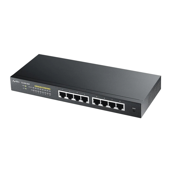
This chapter describes the front panel and rear panel of the Switch and shows you how to make the hardware connections. 3.1 Front Panel Connections The following figures show the front panels of the Switch. Figure 9 Front Panel: GS1900-8 Figure 10 Front Panel: GS1900-8HP Revision A1 Revision B1 Figure 11 Front Panel: GS1900-10HP GS1900 Series User’s Guide... -
Page 25: Ethernet Ports
The Switch has 1000Base-T auto-negotiating, auto-crossover Ethernet ports. In 10/100/1000 Mbps Gigabit Ethernet, the speed can be 10Mbps, 100 Mbps or 1000 Mbps. The duplex mode can be both half or full duplex at 100 Mbps and full duplex only at 1000 Mbps. GS1900 Series User’s Guide... -
Page 26: Sfp Slots
Use the following steps to install a transceiver. Insert the transceiver into the slot with the exposed section of PCB board facing down. Figure 18 Transceiver Installation Example Press the transceiver firmly until it clicks into place. GS1900 Series User’s Guide... -
Page 27: Rear Panel
Figure 20 Opening the Transceiver’s Latch Example Pull the transceiver out of the slot. Figure 21 Transceiver Removal Example 3.2 Rear Panel The following figures show the rear panels of the Switch. Figure 22 Rear Panel: GS1900-8 GS1900 Series User’s Guide... - Page 28 Chapter 3 Hardware Overview Figure 23 Rear Panel: GS1900-8HP Revision A1 Revision B1 Figure 24 Rear Panel: GS1900-10HP Figure 25 Rear Panel: GS1900-16 Figure 26 Rear Panel: GS1900-24E Figure 27 Rear Panel: GS1900-24 Figure 28 Rear Panel: GS1900-24HP GS1900 Series User’s Guide...
-
Page 29: Power Connection
Connect the other end of the cord to a power outlet. Disconnecting the Power The power input connectors can be disconnected from the power source individually. Disconnect the power cord from the power outlet. Disconnect the power cord from the AC power socket. GS1900 Series User’s Guide... -
Page 30: Leds
Green The port is in PoE AT mode. That is, the Switch is following the IEEE 802.3at standard to supply power to this port. Power is not supplied to this port. GS1900 Series User’s Guide... - Page 31 The link to a 100 Mbps Fiber network is up. arrows Blinking The system is transmitting/receiving to/from a 100 Mbps Fiber network. Green The link to a 1 Gbps Fiber network is up. Blinking The system is transmitting/receiving to/from 1 Gbps Mbps Fiber network. GS1900 Series User’s Guide...
-
Page 32: Zon Utility
ZON Utility screen and you can perform tasks like basic configuration of the devices and batch firmware upgrade in it. You can download the ZON Utility at www.zyxel.com and install it on a PC. The following figure shows the ZON Utility screen. Figure 31 ZON Utility Screen GS1900 Series User’s Guide... -
Page 33: The Web Configurator
Enter the user name (default: “admin”) and password (default: “1234”). Click Login. If you logged in using the default user name and password, getting start appears. The Getting Start screen appears every time you log in using the default user name and default password. GS1900 Series User’s Guide... -
Page 34: Navigating The Web Configurator
Click this to open the help page for the current screen. Click Logout in a screen to exit the web configurator. You have to log in with your password again after you log out. This is recommended after you finish a management session for security reasons. GS1900 Series User’s Guide... -
Page 35: Navigation Panel
Switch’s navigation panel menus and their screens. Figure 35 Navigation Panel Getting Start Getting Start displays general device information, system status, system resource usage, and interface status. For details on Getting Start features, see Chapter 6 on page GS1900 Series User’s Guide... -
Page 36: Monitor Menu
IGMP snooping and create multicast VLANs. IGMP VLAN Displays VLAN settings. Statistics Displays statistics settings. Group Displays group settings. Router Displays router settings. Spanning Tree This link takes you to screens where you can view CIST, MST, STP preventing network loops. GS1900 Series User’s Guide... -
Page 37: Configuration Menu
Switch to supply power over Ethernet (PoE). Port This link takes you to a screen where you can configure port PoE settings. Bandwidth Bandwidth Control Configure egress global burst and port rate. Management Storm Control Port Configure port settings. GS1900 Series User’s Guide... - Page 38 This link takes you to screens where you can configure the RSTP/ MRSTP/MSTP to prevent network loops. Global Configure global settings. STP Port Configure STP port settings. CIST Configure CIST settings. CIST Port Configure CIST port settings. Configure MST settings. GS1900 Series User’s Guide...
- Page 39 Configure syslog, SNMP, error disable, HTTP/HTTPS, users and remote access control. Syslog Global Configure global settings. Local Configure local settings. Remote Configure remote settings. SNMP Global Configure global settings. Community Configure community settings. Group Configure group settings. User Configure users settings. GS1900 Series User’s Guide...
- Page 40 Port Test Cable Diag Manage cable diag and test results. PING IPv4 Manage ping test settings. IPv6 Manage IPv6 ping test settings. Trace Trace Route Manage trace route settings. Reboot Reset the system. GS1900 Series User’s Guide...
-
Page 41: Getting Start
Use the drop-box to select: None, 5 seconds, 10 seconds, 15 seconds, 20 seconds, 25 seconds, or 30 seconds. Virtual Device Displays an image of the Switch. Wizard Displays the following links: Start up, VLAN, QoS, and link aggregation. GS1900 Series User’s Guide... -
Page 42: Wizard
In start up, you can set up IP/DNS, set up your username/password, and view finished results. In order to set up your IP/DNS, please do the following. Click Getting Start > Start up > 1 Step 1 Set up IP to access this screen. GS1900 Series User’s Guide... - Page 43 This field displays the NTP time servers from which the Switch gets the time and date. Protocol) Next Click Next to show the next screen. After clicking Next, the set up your user name screen appears. GS1900 Series User’s Guide...
- Page 44 The default username is admin and associated default password is 1234. Previous Click Previous to show the previous screen. Next Click Next to show the next screen. After clicking Next, the finish screen appears. Figure 39 Getting Start > Start up > 3 Step 3 Finish GS1900 Series User’s Guide...
- Page 45 In order to create VLAN, please do the following. Click Getting Start > VLAN > 1 Step 1 Create VLAN to access this screen. Figure 40 Getting Start > VLAN > 1 Step 1 Create VLAN GS1900 Series User’s Guide...
- Page 46 Untag Ports belonging to the specified VLAN don't tag all outgoing frames transmitted. Previous Click Previous to show the previous screen. Next Click Next to show the next screen. After clicking Next, the finish screen appears. GS1900 Series User’s Guide...
- Page 47 In QoS, you can create QoS settings, and view finished results. In order to create QoS settings, please do the following. Click Getting Start > QoS > 1 Step 1 QoS (Quality ofOf Service) to access this screen. GS1900 Series User’s Guide...
- Page 48 Click and drag icons located on the left to desired preference. Next Click Next to show the next screen. After clicking Next, the finish screen appears. Figure 44 Getting Start > QoS > 2 Step 2 Finish GS1900 Series User’s Guide...
- Page 49 Click and drag icons located on the left to desired preference. Group 6 Click and drag icons located on the left to desired preference. Group 7 Click and drag icons located on the left to desired preference. GS1900 Series User’s Guide...
- Page 50 Displays summary results. Group 6 Displays summary results. Group 7 Displays summary results. Group 8 Displays summary results. Previous Click Previous to show the previous screen. Finish Review the information and click Finish to create the task. GS1900 Series User’s Guide...
-
Page 51: Technical Reference
Technical Reference... -
Page 52: Monitor: System
The factory default subnet mask is 255.255.255.0. 7.2.1 IPv4 Use this screen to view the Switch’s IPv4 information. Click Monitor > System > IP > IPv4 to open this screen. Figure 47 Monitor > System > IP > IPv4 GS1900 Series User’s Guide... -
Page 53: Ipv6
This field displays IP address of the Switch in the IP domain. IPv6 Gateway This field displays the IP address of the default outgoing gateway. DHCPv6 Client This field displays the Switch’s DHCP settings when it is acting as a DHCPv6 client. GS1900 Series User’s Guide... -
Page 54: Information
This field displays the descriptive name of the Switch for identification purposes. System Location This field displays the geographic location of the Switch for identification purposes. System Contact This field displays the person in charge of the Switch for identification purposes. GS1900 Series User’s Guide... -
Page 55: Monitor: Port
Figure 50 Monitor > Port > Port > Status Each field is described in the following table. Table 24 Monitor > Port > Port > Status LABEL DESCRIPTION Port This is the port index number. Port Name A descriptive name that identifies this port. GS1900 Series User’s Guide... -
Page 56: Port Counters
Figure 51 Monitor > Port > Port > Port Counters Each field is described in the following table. Table 25 Monitor > Port > Port > Port Counters LABEL DESCRIPTION Interface Port This field displays the port. GS1900 Series User’s Guide... - Page 57 This field displays the etherStatsOverSizePkts. etherStatsFragments This field displays the etherStatsFragments. etherStatsJabbers This field displays the etherStatsJabbers. etherStatsCollisions This field displays the etherStatsCollisions. etherStatsPkts64Octets This field displays the etherStatsPkts64Octets. etherStatsPkts65to127Octets This field displays the etherStatsPkts65to127Octets. GS1900 Series User’s Guide...
-
Page 58: Bandwidth Utilization
This field displays the link down. Refresh period This field displays the refresh period. This field displays the IFG. Transmitted (Tx) traffic during the last time interval in seconds. Received (Rx) traffic during thetime interval in seconds. GS1900 Series User’s Guide... -
Page 59: Poe
PoE ports. The total power of GS1900-10HP is 77W and GS1900-8HP is 70W. Consuming This field displays the total amount of power the Switch is currently supplying to the Power(W) connected PoE-enabled devices. GS1900 Series User’s Guide... -
Page 60: Bandwidth Management
This field specifies the current egress burst size in bytes all ports. Burst Port Rate View the maximum bandwidth allowed in kilobits per second (Kbps) for the traffic flow on a port. Port This field displays the port number. GS1900 Series User’s Guide... -
Page 61: Storm Control
Displays how many unknown unicast packets the port receives (in pps). Unicast (pps) Action Displays the action the device takes when a limit is reached. The following options are available: • Drop - drop the packet. • Shutdown - shutdown the connection. GS1900 Series User’s Guide... -
Page 62: Monitor: Vlan
66) displays the global and port settings of the Switch. 9.2 VLAN Use this screen to view Switch VLAN settings. 9.2.1 VLAN Use this screen to view the Switch’s VLAN settings. Click Monitor > VLAN > VLAN > VLAN to access this screen. GS1900 Series User’s Guide... -
Page 63: Port
This is the port VLAN identification number. A PVID (Port VLAN ID) is a tag that adds to incoming untagged frames received on a port so that the frames are forwarded to the VLAN group that the tag defines. GS1900 Series User’s Guide... -
Page 64: Vlan Port
Figure 59 Monitor > VLAN > VLAN > VLAN Port Each field is described in the following table. Table 32 Monitor > VLAN > VLAN > VLAN Port LABEL DESCRIPTION VLAN Port VLAN ID This is the VLAN identification number. GS1900 Series User’s Guide... -
Page 65: Guest Vlan
Figure 60 Guest VLAN Example VLAN 100 VLAN 102 Internet Use this screen to view the Switch’s guest VLAN. Click Monitor > VLAN > Guest VLAN to access this screen. Figure 61 Monitor > VLAN > Guest VLAN GS1900 Series User’s Guide... -
Page 66: Voice Vlan
This is the voice VLAN identification number. Cos/802.1p This displays the packet’s 802.1p priority field. Remark Cos/802.1p This field displays the state of the cos/802.1p. Aging Time (30-65536 min) Displays the time interval (from 30 to 65536) in minutes. Port GS1900 Series User’s Guide... - Page 67 Chapter 9 Monitor: VLAN Table 34 Monitor > VLAN > Voice VLAN (continued) LABEL DESCRIPTION Port This field displays a port number. State This field displays the state of a port. GS1900 Series User’s Guide...
-
Page 68: Monitor: Mac Table
Figure 63 MAC Table Flowchart This link takes you to a screen where you can view the MAC address and VLAN ID of a device attach to a port. You can also view what kind of MAC address it is. GS1900 Series User’s Guide... -
Page 69: What You Can Do In This Chapter
This shows whether the MAC address is dynamic (learned by the Switch) or static (manually entered in the Static MAC Forwarding screen). Port This is the port from which the above MAC address was learned. Total Entries Displays the number of total entries. GS1900 Series User’s Guide... -
Page 70: Monitor: Link Aggregation
70) displays link aggregation status. 11.2 Link Aggregation Use the Link Aggregation screens to view Switch link aggregation status. Click Monitor > Link Aggregation > LAG to access this screen. Figure 65 Monitor > Link Aggregation > LAG GS1900 Series User’s Guide... - Page 71 Down when it is not. When no any physical port is binding with this group, it displays NotPresent. Active Member Displays if this member is an active member of a trunk. Standby Member Displays if this member is an standby member of a trunk. GS1900 Series User’s Guide...
-
Page 72: Monitor: Loop Guard
B. Since switch B is in loop state, the probe packet P returns to port N on A. The Switch then shuts down port N to ensure that the rest of the network is not affected by the switch in loop state. GS1900 Series User’s Guide... -
Page 73: What You Can Do In This Chapter
• The Loop Guard screen (Section 12.2 on page 73) displays loop guard status. 12.2 Loop Guard Use the Loop Guard screen to view Switch loop guard status. Click Monitor > Loop Guard to access this screen. GS1900 Series User’s Guide... - Page 74 DESCRIPTION Loop Guard Status Port This field displays a port number. Status This field displays the status. Time Left (sec) This field displays the amount of time left in seconds. Action This field displays the action. GS1900 Series User’s Guide...
-
Page 75: Monitor: Multicast
Use this screen to view Switch various multicast features. 13.2.1 Vlan Use this screen to view the Switch’s IGMP vlan. Click Monitor > Multicast > IGMP > Vlan to access this screen. Figure 70 Monitor > Multicast > IGMP > Vlan GS1900 Series User’s Guide... -
Page 76: Statistics
This field displays the number of total entries. 13.2.2 Statistics Use this screen to view the Switch’s IGMP statistics. Click Monitor > Multicast > IGMP > Statistics to access this screen. Figure 71 Monitor > Multicast > IGMP > Statistics GS1900 Series User’s Guide... -
Page 77: Group
Figure 72 Monitor > Multicast > IGMP > Statistics > Action 13.2.3 Group Use this screen to view the Switch’s IGMP group. Click Monitor > Multicast > IGMP > Group to access this screen. GS1900 Series User’s Guide... -
Page 78: Router
This field displays the dynamic router ports. Static Router Ports This field displays the static router ports. Forbidden Router Ports This field displays the forbidden router ports. Total Entries This field displays the number of total entries. GS1900 Series User’s Guide... -
Page 79: Monitor: Spanning Tree
Use this screen to view Switch spanning tree settings. 14.2.1 CIST Use this screen to view the Switch’s spanning tree CIST instance. Click Monitor > Spanning Tree > CIST to access this screen. Figure 75 Monitor > Spanning Tree > CIST GS1900 Series User’s Guide... -
Page 80: Cist Port
14.2.2 CIST Port Use this screen to view the Switch’s spanning tree CIST port status. Click Monitor > Spanning Tree > CIST Port to access this screen. Figure 76 Monitor > Spanning Tree > CIST Port GS1900 Series User’s Guide... -
Page 81: Mst
This field displays the state of the port. 14.2.3 MST Use this screen to view the Switch’s spanning tree MST instance. Click Monitor > Spanning Tree > MST to access this screen. Figure 77 Monitor > Spanning Tree > MST GS1900 Series User’s Guide... -
Page 82: Mst Port
Select a number from the drop-down menu to display results. Port This field displays the port number. MSTI ID A VLAN can be mapped to a specific Multiple Spanning Tree Instance (MSTI). MSTI allows multiple VLANs to use the same spanning tree. GS1900 Series User’s Guide... -
Page 83: Stp Statistics
Note: In this user’s guide, “STP” refers to both STP and RSTP. Use this screen to view the Switch’s spanning tree STP statistics. Click Monitor > Spanning Tree > STP Statistics to access this screen. Figure 79 Monitor > Spanning Tree > STP Statistics GS1900 Series User’s Guide... - Page 84 This field displays the Multiple Spanning Tree Protocol (MSTP) BDPUs received. Received Configuration This field displays the configuration BDPUs transmitted. BDPUs Transmitted TCN BDPUs This field displays the TCN BDPUs transmitted. Transmitted MSTP BDPUs This field displays the Multiple Spanning Tree Protocol (MSTP) BDPUs transmitted. Transmitted GS1900 Series User’s Guide...
-
Page 85: Monitor: Lldp
15.2.1 Statistics Use this screen to view the Switch’s LLDP global and port statistics. Click Monitor > LLDP > Statistics to access this screen. Figure 80 Monitor > LLDP > Statistics GS1900 Series User’s Guide... -
Page 86: Remote Information
This field displays the port ID subtype. Port ID This field displays the port ID. System Name This field displays the descriptive name of the Switch for identification purposes. Time to Live This field displays the live time of this entry. GS1900 Series User’s Guide... -
Page 87: Overloading
Optional TLVs This field displays how many bytes used by optional TLVs. MED Inventory This field displays how many bytes used by MED inventory. 802.1 TLVs This field displays how many bytes used by 802.1 TLVs. GS1900 Series User’s Guide... -
Page 88: Monitor: Security
When total MAC address entry is 8k, static MAC can't be configured. Use this screen to view Switch port security settings. Click Monitor > Security > Port Security to access this screen. Figure 83 Monitor > Security > Port Security GS1900 Series User’s Guide... -
Page 89: Port
Each field is described in the following table. Table 51 Monitor > Security > 802.1X > Port LABEL DESCRIPTION Port This label shows the port you are viewing. Status This field displays status of the port. GS1900 Series User’s Guide... -
Page 90: Authenticated Hosts
This label shows the port you are viewing. Session Time This label shows the session time. Authentication This label shows the authentication method. Method MAC Address This field displays the source MAC address in the binding. GS1900 Series User’s Guide... -
Page 91: Monitor: Management
(Section 17.3 on page 92) displays global and port. 17.2 Syslog Use this screen to view Switch syslog management. Click Monitor > Management > Syslog to access this screen. Figure 86 Monitor > Management > Syslog GS1900 Series User’s Guide... -
Page 92: Error Disable
This link takes you to a screen where you can view CPU protection and error disable recovery. Use this screen to view Switch global and port error disable management. Click Monitor > Management > Error Disable to access this screen. GS1900 Series User’s Guide... - Page 93 This field displays the supported features that allow the Switch to shut down a port or Reason discard packets on a port according to the feature requirements and what action you configure. Time Left (sec) This field displays the time left in seconds. Action This field displays the action. GS1900 Series User’s Guide...
-
Page 94: Configuration: System
18.2.1 The IPv4 Screen Use this screen to view the IPv4 interface status and Switch’s management IPv4 addresses. Click Configuration > System > IP > IPv4 to open this screen. Figure 88 Configuration > System > IP > IPv4 GS1900 Series User’s Guide... -
Page 95: The Ipv6 Screen
Select Enable to allow the device to act as a DHCPv6 client or Disable to disallow it. This field displays the Switch’s DHCP settings when it is acting as a DHCPv6 client. Auto Select Enable to allow the device to auto-configure the IPv6 properties or Disable to Configuration manually enter the properties. GS1900 Series User’s Guide... -
Page 96: Time
Select the system date and time values from the dropdown lists. Time Zone Select the time zone from the dropdown list. Daylight Saving Select Enable to use Daylight Saving Time to offset the system time or Disable not adjust Time system time. GS1900 Series User’s Guide... -
Page 97: The Sntp Server Screen
18.4.1 The System Information Screen In the navigation panel, click Configuration > System > System Information to display the screen as shown. You can set the system name, system location, and system contact. GS1900 Series User’s Guide... - Page 98 Enter the geographic location of the Switch for identification purposes. System Contact Enter the person in charge of the Switch for identification purposes. Apply Click Apply to save the changes. Cancel Click Cancel to discard the changes. GS1900 Series User’s Guide...
-
Page 99: Configuration: Port
Table 60 Configuration > Port > Port > Port LABEL DESCRIPTION Port Edit Select this check box to configure the properties of a port. Click the Edit button change the properties of the port. Port Displays the port index number. GS1900 Series User’s Guide... -
Page 100: The Port Edit Screen
19.2.1 The Port Edit Screen Use this screen to configure Switch port settings. Click Configuration > Port > Port > Edit to open this screen. Figure 94 Configuration > Port > Port > Edit GS1900 Series User’s Guide... -
Page 101: Eee
Use this screen to view Switch port Energy-Efficient Ethernet (EEE) settings and select ports for configuration. Click Configuration > Port > EEE > EEE to open this screen. Figure 95 Configuration > Port > EEE > EEE GS1900 Series User’s Guide... -
Page 102: The Eee Edit Screen
Ethernet (PoE) standards. The Switch is Power Sourcing Equipment (PSE) because it provides a source of power via its Ethernet ports, and each device that receives power through an Ethernet port is a Powered Device (PD). GS1900 Series User’s Guide... -
Page 103: The Global Screen
Click Cancel to discard the changes. 19.4.2 The Port Screen Use this screen to view Switch port PoE settings and select ports for configuration. Click Configuration > Port > PoE > Port to open this screen. GS1900 Series User’s Guide... - Page 104 Medium has the Switch assign power to the port after all critical and high priority ports are served. • Low has the Switch assign power to the port after all critical, high and medium priority ports are served. GS1900 Series User’s Guide...
-
Page 105: The Poe Edit Screen
Click Apply to save the changes. Cancel Click Cancel to discard the changes. 19.4.3 The PoE Edit Screen Use this screen to configure Switch port PoE settings. Click Configuration > Port > PoE > Port > Edit to open this screen. GS1900 Series User’s Guide... - Page 106 PoE Plus. An IEEE 802.3at compatible device is referred to as Type 2. Power Class 4 (High Power) can only be used by Type 2 devices. If the connected PD requires a Class 4 current when it is turned on, it will be powered up in this mode. GS1900 Series User’s Guide...
- Page 107 This field displays Enable if the Switch applies a wider range for PD detection. Otherwise, it displays Disable. Apply Click Apply to save the changes. Cancel Click Cancel to discard the changes. GS1900 Series User’s Guide...
-
Page 108: Bandwidth Management
Specify the current egress burst size in bytes for all ports. Burst Port Rate Edit Select this check box to configure the properties of a port. Click the Edit button change the properties of the port. Port Displays the port index number. GS1900 Series User’s Guide... -
Page 109: The Port Rate Edit Screen
Select Enable to activate egress peak rate limits on the port(s). Egress Enter the maximum bandwidth allowed in kilobits per second (Kbps) for the outgoing traffic Bandwidth flow on a port. (Kbps) Apply Click Apply to save the changes. Cancel Click Cancel to discard the changes. GS1900 Series User’s Guide... -
Page 110: Storm Control
Displays how many unicast packets the port receives per second. Unicast (pps) Action Displays the action the device takes when a limit is reached. The following options are available: • Drop - drop the packet. • Shutdown - shutdown the connection. GS1900 Series User’s Guide... -
Page 111: The Port Edit Screen
Click the Enable checkbox to active the feature. Unicast (pps) Enter the maximum number of unicast packets the port can receive per second. Apply Click Apply to save the changes. Cancel Click Cancel to discard the changes. GS1900 Series User’s Guide... -
Page 112: Configuration: Vlan
The Guest VLAN screen (Section 20.3 on page 118) displays the global and port settings of the Switch. • The Voice VLAN screen (Section 20.4 on page 120) displays the global, OUI, and port settings of the Switch. GS1900 Series User’s Guide... -
Page 113: Vlan
20.2.2 The VLAN Add Screen Use this screen to add a VLAN. Click Configuration > VLAN > VLAN > VLAN > Add to open this screen. Figure 105 Configuration > VLAN > VLAN > VLAN > Add GS1900 Series User’s Guide... -
Page 114: The Port Screen
20.2.3 The Port Screen Use this screen to view port settings and select VLANs for configuration. Click Configuration > VLAN > VLAN > Port to open this screen. Figure 106 Configuration > VLAN > VLAN > Port GS1900 Series User’s Guide... -
Page 115: The Port Edit Screen
Table 74 Configuration > VLAN > VLAN > Port > Edit LABEL DESCRIPTION Port Port Select Displays the list of port index numbers that are being configured. PVID Enter a number between 1 and 4094 as the port VLAN ID. GS1900 Series User’s Guide... -
Page 116: The Vlan Port Screen
Port-based VLANs are specific only to the Switch on which they were created. Use this screen to view VLAN port settings. Click Configuration > VLAN > VLAN > VLAN Port to open this screen. GS1900 Series User’s Guide... - Page 117 Select Tagged to set the port TX tag status to tagged in the VLAN. Select Untagged to set the port TX tag status to untagged in the VLAN. Apply Click Apply to save the changes. Cancel Click Cancel to discard the changes. GS1900 Series User’s Guide...
-
Page 118: Guest Vlan
Figure 110 Configuration > VLAN > Guest VLAN > Global The following table describes the labels in this screen. Table 76 Configuration > VLAN > Guest VLAN > Global LABEL DESCRIPTION Global State Select to enable the global Guest VLAN feature. GS1900 Series User’s Guide... -
Page 119: The Port Screen
Display the state of the selected port. 20.3.3 The Port Edit Screen Use this screen to configure the guest VLAN port EEE settings. Click Configuration > VLAN > Guest VLAN > Port > Edit to open this screen. GS1900 Series User’s Guide... -
Page 120: Voice Vlan
Use this screen to view and configure voice VLAN settings. 20.4.1 The Global Screen Use this screen to configure the global Voice VLAN settings. Click Configuration > VLAN > Voice VLAN > Global to open this screen. GS1900 Series User’s Guide... -
Page 121: The Oui Screen
Use this screen to view the OUI settings. The maximum number of entries is 16. Modifying the OUI table will restart auto detection of OUI process. Click Configuration > VLAN > Voice VLAN > OUI to open this screen. GS1900 Series User’s Guide... -
Page 122: The Oui Add/Edit Screen
20.4.3 The OUI Add/Edit Screen Use this screen to add/edit an OUI address. Click Configuration > VLAN > Voice VLAN > OUI > Add/Edit to open this screen. Figure 115 Configuration > VLAN > Voice VLAN > OUI > Add/Edit GS1900 Series User’s Guide... -
Page 123: The Port Screen
The following table describes the labels in this screen. Table 82 Configuration > VLAN > Voice VLAN > Port LABEL DESCRIPTION Port Edit Select this check box to configure the properties of a port. Click the Edit button change the properties of the port. GS1900 Series User’s Guide... -
Page 124: The Port Edit Screen
MAC addresses in the Voice VLAN will be blocked for 10 seconds. Possible port modes are: • Enabled: Enable Voice VLAN security mode operation. • Disabled: Disable Voice VLAN security mode operation. Apply Click Apply to save the changes. Cancel Click Cancel to discard the changes. GS1900 Series User’s Guide... -
Page 125: Configuration: Mac Table
The following table describes the labels in this screen. Table 84 Configuration > MAC Table > Static MAC LABEL DESCRIPTION Static MAC Click Add to create a new Static MAC entry. MAC Address Displays the object MAC address from which this incoming frame came. GS1900 Series User’s Guide... -
Page 126: The Static Mac Add Screen
Click Cancel to discard the changes. 21.2.3 The Filtering MAC Screen Use this screen to view Filtering MAC addresses. Click Configuration > MAC Table > Filtering MAC to open this screen. Figure 120 Configuration > MAC Table > Filtering MAC GS1900 Series User’s Guide... -
Page 127: The Filtering Mac Add Screen
Use this screen to enter the Dynamic MAC Age. The dynamic MAC age is how long all dynamically learned MAC addresses remain in the MAC address table before they age out (and must be relearned). Click Configuration > MAC Table > Dynamic Age to open this screen. GS1900 Series User’s Guide... - Page 128 Dynamic MAC Age Aging Time Enter the aging time of the MAC address. The value can be between 10 and 630 seconds. Apply Click Apply to save the changes. Cancel Click Cancel to discard the changes. GS1900 Series User’s Guide...
-
Page 129: Configuration: Link Aggregation
This ensures increased network stability and control over the trunk groups on your Switch. 22.2.1 The Global Screen Use this screen to configure global Link Aggregation settings. Click Configuration > Link Aggregation > Global to open this screen. GS1900 Series User’s Guide... -
Page 130: The Lag Management Screen
Click Cancel to discard the changes. 22.2.2 The LAG Management Screen Use this screen to view LAG management settings. Click Configuration > Link Aggregation > LAG Management to open this screen. Figure 124 Configuration > Link Aggregation > LAG Management GS1900 Series User’s Guide... -
Page 131: The Lag Add Screen
22.2.3 The LAG Add Screen Use this screen to add a LAG. Click Configuration > Link Aggregation > LAG Management > Add to open this screen. Figure 125 Configuration > Link Aggregation > LAG Management > Add GS1900 Series User’s Guide... -
Page 132: The Lag Port Screen
100M, 10M, 100M, or 1000M. Duplex Displays the duplex value as Full, Half, or Auto. FlowCtrl State Displays whether flow control is Enable/Disable. FlowCtrl Status Displays whether flow control is in use (Enable) or not (Disable). GS1900 Series User’s Guide... -
Page 133: The Lag Port Edit Screen
Click Apply to save the changes. Cancel Click Cancel to discard the changes. 22.2.6 The LACP Port Screen Use this screen to view LACP Port settings. Click Configuration > Link Aggregation > LACP Port to open this screen. GS1900 Series User’s Guide... -
Page 134: The Lacp Port Edit Screen
22.2.7 The LACP Port Edit Screen Use this screen to edit a LACP Port. Click Configuration > Link Aggregation > LACP Port > Edit to open this screen. Figure 129 Configuration > Link Aggregation > LACP Port > Edit GS1900 Series User’s Guide... - Page 135 Enter a value for the port priority. The number can be between 1 and 65,535. Timer Select a timer value of either 1 second or 30 seconds. Apply Click Apply to save the changes. Cancel Click Cancel to discard the changes. GS1900 Series User’s Guide...
-
Page 136: Configuration: Loop Guard
Figure 130 Configuration > Loop Guard The following table describes the labels in this screen. Table 96 Configuration > Loop Guard LABEL DESCRIPTION Global State Select Enable to activate loop protection on this switch. GS1900 Series User’s Guide... -
Page 137: The Loop Guard Port
Displays the action to take by the Switch. The options are Log, Shutdown Port, and Shutdown and Log. 23.2.3 The Port Edit Screen Use this screen to configure a Loop Guard port. Click Configuration > Loop Guard > Port > Edit to open this screen. GS1900 Series User’s Guide... - Page 138 Displays the list of port index numbers to be configured. State Select Enable to use the Admin Enabled feature. Action Select the action to take by the Switch. Apply Click Apply to save the changes. Cancel Click Cancel to discard the changes. GS1900 Series User’s Guide...
-
Page 139: Configuration: Mirror
The Switch supports local port mirroring. 24.2.1 The Mirror Screen Use this screen to configure Mirroring. Click Configuration > Mirror to open this screen. Figure 133 Configuration > Mirror GS1900 Series User’s Guide... - Page 140 Click > to move a severity type to the acting box from the available box. < Click < to move a severity type from the acting box to the available box. Apply Click Apply to save the changes. Cancel Click Cancel to discard the changes. GS1900 Series User’s Guide...
-
Page 141: Configuration: Multicast
The following table describes the labels in this screen. Table 100 Configuration > Multicast > IGMP LABEL DESCRIPTION IGMP Global Snooping Status Select Enable to turn on IGMP packet snooping or Disable to turn snooping off. GS1900 Series User’s Guide... -
Page 142: The Vlan Screen
Last Member Query Count Displays the number of queries. Interval (sec) Displays the amount of time (in milliseconds) between the IGMP group-specific queries sent by an upstream port when an IGMP Done message is received. Querier GS1900 Series User’s Guide... -
Page 143: The Edit Igmp Screen
The value can be between 30 and 18000. Max. Response Enter the amount of time (in seconds) the router connected to the upstream port waits for Interval (sec) a response to an IGMP general query message. GS1900 Series User’s Guide... -
Page 144: The Router Port Screen
Click Delete to remove the entry. 25.2.5 The Add/Edit Router Port Screen Use this screen to configure the Router Port settings. Click Configuration > Multicast > IGMP > Router Port > Add/Modify to open this screen. GS1900 Series User’s Guide... -
Page 145: The Profile Screen
Click Apply to save the changes. Cancel Click Cancel to discard the changes. 25.2.6 The Profile Screen Use this screen to view the IGMP Profile settings. Click Configuration > Multicast > IGMP > Profile to open this screen. GS1900 Series User’s Guide... -
Page 146: The Add/Edit Profile Screen
The following table describes the labels in this screen. Table 106 Configuration > Multicast > IGMP > Profile > Add/Edit LABEL DESCRIPTION IGMP Profile Profile Enter the Profile index number. Group From Enter the profile start group IP address. GS1900 Series User’s Guide... -
Page 147: The Throttling Screen
Filter Profile ID Displays the throttling filter profile ID. 25.2.9 The Add/Edit Throttling Screen Use this screen to configure the Throttling settings. Click Configuration > Multicast > IGMP > Throttling > Add/Edit to open this screen. GS1900 Series User’s Guide... - Page 148 Select the action taken by the groups to be Deny or Replace. Number Action Filter Profile ID Select the throttling filter profile ID from the dropdown list. Apply Click Apply to save the changes. Cancel Click Cancel to discard the changes. GS1900 Series User’s Guide...
-
Page 149: Configuration: Spanning Tree
It allows a Switch to interact with other (R)STP-compliant switches in your network to ensure that only one path exists between any two stations on the network. 26.2.1 The Global Screen Use this screen to view the Global settings. Click Configuration > Spanning Tree to open this screen. GS1900 Series User’s Guide... -
Page 150: The Stp Port Screen
Click Apply to save the changes. Cancel Click Cancel to discard the changes. 26.2.2 The STP Port Screen Use this screen to view the STP Port settings. Click Configuration > Spanning Tree > STP Port to open this screen. GS1900 Series User’s Guide... -
Page 151: The Stp Port Edit Screen
Displays the P2P MAC status as Yes or No. 26.2.3 The STP Port Edit Screen Use this screen to configure the STP Port Edit settings. Click Configuration > Spanning Tree > STP Port > Edit to open this screen. GS1900 Series User’s Guide... -
Page 152: The Cist Screen
Click Apply to save the changes. Cancel Click Cancel to discard the changes. 26.2.4 The CIST Screen Use this screen to view the CIST settings. Click Configuration > Spanning Tree > CIST to open this screen. GS1900 Series User’s Guide... - Page 153 This is the time interval in seconds between BPDU (Bridge Protocol Data Units) configuration message generations by the root switch. The allowed range is 1 to 10 seconds. Apply Click Apply to save the changes. Cancel Click Cancel to discard the changes. GS1900 Series User’s Guide...
-
Page 154: The Cist Port Screen
Displays the internal path cost. Cost 26.2.6 The CIST Port Edit Screen Use this screen to configure the CIST Port Edit settings. Click Configuration > Spanning Tree > CIST Port > Edit to open this screen. GS1900 Series User’s Guide... -
Page 155: The Mst Screen
Table 115 Configuration > Spanning Tree > MST LABEL DESCRIPTION MST Instance Click Add to create a new MST Instance entry. MSTI Displays the Multiple Spanning Tree Instance(s) (MSTI). VLAN List Display a list of MSTI VLANs. GS1900 Series User’s Guide... -
Page 156: The Add/Modify Mst Screen
Click Apply to save the changes. Cancel Click Cancel to discard the changes. 26.2.9 The MST Port Screen Use this screen to view the MST Port settings. Click Configuration > Spanning Tree > MST Port to open this screen. GS1900 Series User’s Guide... -
Page 157: The Mst Port Edit Screen
Displays the internal path cost. Cost 26.2.10 The MST Port Edit Screen Use this screen to configure the MST Port Edit settings. Click Configuration > Spanning Tree > MST Port > Edit to open this screen. GS1900 Series User’s Guide... - Page 158 0 and 255 and the default value is 128. Internal Path Enter the internal path cost. Enter 0 for Auto. Cost (0=Auto) Apply Click Apply to save the changes. Cancel Click Cancel to discard the changes. GS1900 Series User’s Guide...
-
Page 159: Configuration: Lldp
Figure 153 Configuration > LLDP > Global The following table describes the labels in this screen. Table 119 Configuration > LLDP > Global LABEL DESCRIPTION Global State Select Enable to activate the global LLDP. GS1900 Series User’s Guide... -
Page 160: The Port Screen
Apply Click Apply to save the changes. Cancel Click Cancel to discard the changes. 27.2.2 The Port Screen Use this screen to view the Port settings. Click Configuration > LLDP > Port to open this screen. GS1900 Series User’s Guide... -
Page 161: The Port Edit Screen
MFS - 802.3 Maximum Frame Size • MA - Management Address 27.2.3 The Port Edit Screen Use this screen to configure the Port Edit settings. Click Configuration > LLDP > Port > Edit to open this screen. GS1900 Series User’s Guide... -
Page 162: The Local Information Screen
Click Apply to save the changes. Cancel Click Cancel to discard the changes. 27.2.4 The Local Information Screen Use this screen to view the Local Information settings. Click Configuration > LLDP > Local Information to open this screen. GS1900 Series User’s Guide... - Page 163 Displays the chassis ID subtype. Subtype Chassis ID The Chassis ID is the identification of the neighbor's LLDP frames. System Name System Name is the name advertised by the neighbor unit. System Displays the System Description. Description GS1900 Series User’s Guide...
-
Page 164: The Local Information Edit Screen
ELIN to be used for emergency calling. 27.2.5 The Local Information Edit Screen Use this screen to configure the Port Edit settings. Click Configuration > LLDP > Local Information > Edit to open this screen. GS1900 Series User’s Guide... - Page 165 The following table describes the labels in this screen. Table 123 Configuration > LLDP > Local Information > Edit LABEL DESCRIPTION MED Port Location Port List Displays the index number of the LLDP port(s). The value is made of 16 pairs of hexadecimal characters. GS1900 Series User’s Guide...
- Page 166 Room no.: Room number - Example: 450F. • Place type: Place type - Example: Office. • Postal community name: Postal community name - Example: Leonia. • P.O. Box: Post office box (P.O. BOX) - Example: 12345. GS1900 Series User’s Guide...
-
Page 167: The Med Network Policy Screen
Click Delete to remove the entry. 27.2.7 The MED Network Policy Add/Edit Screen Use this screen to configure the Port Edit settings. Click Configuration > LLDP > MED Network Policy > Add/Edit to open this screen. GS1900 Series User’s Guide... - Page 168 TCP with buffering would not be an intended use of this application type. 8. Video Signalling - for use in network topologies that require a separate pol- icy for the video signalling than for the video media. GS1900 Series User’s Guide...
-
Page 169: The Med Port Screen
Select this check box to configure the properties of a port. Click the Edit button change the properties of the port. Port Displays the MED Port value. State Displays the state of the MED port as Enable or Disable. Network Policy Displays the Network Policy value. GS1900 Series User’s Guide... -
Page 170: The Med Port Add/Edit Screen
Select one or more of the MED Optional TLVs: TLVs • Network Policy • Location • PoE PSE • Inventory MED Network Select one or more of the MED Network Policies in Available and move them to Acting Policy to activate. GS1900 Series User’s Guide... - Page 171 Chapter 27 Configuration: LLDP Table 127 Configuration > LLDP > MED Port > Edit (continued) LABEL DESCRIPTION Apply Click Apply to save the changes. Cancel Click Cancel to discard the changes. GS1900 Series User’s Guide...
-
Page 172: Configuration: Qos
28.2.1 The Port Screen Use this screen to view the Port settings. Click Configuration > QoS > General to open this screen. Figure 162 Configuration > QoS > General GS1900 Series User’s Guide... -
Page 173: The Port Edit Screen
Select Enable to activate CoS Remark. DSCP Remark Select Enable to activate DSCP Remark. IP Precedence Select Enable to activate IP Precedence Remark. Remark Apply Click Apply to save the changes. Cancel Click Cancel to discard the changes. GS1900 Series User’s Guide... -
Page 174: The Queue Screen
Click Apply to save the changes. Cancel Click Cancel to discard the changes. 28.2.4 The CoS Mapping Screen Use this screen to configure the Cos Mapping settings. Click Configuration > QoS > General > CoS Mapping to open this screen. GS1900 Series User’s Guide... - Page 175 Displays a listing of the Queue ID, range: 0 - 7. Class of Service (CoS) (0-7) Click the drop-down menu to map the Queue ID to a specific CoS. Apply Click Apply to save the changes. Cancel Click Cancel to discard the changes. GS1900 Series User’s Guide...
-
Page 176: The Dscp Mapping Screen
Queue ID Displays the DSCP Queue ID value. Queue to DSCP Mapping DSCP (0-63) Select the DSCP mapping value from the dropdown list. Apply Click Apply to save the changes. Cancel Click Cancel to discard the changes. GS1900 Series User’s Guide... -
Page 177: The Ip Precedence Mapping Screen
IP Precedence to Queue Mapping IP Precedence Displays a listing of IP Precedence, range: 0 - 7. Queue ID (0-7) Click the drop-down menu to map an IP Precedence designation to a specific Queue ID (0 - GS1900 Series User’s Guide... -
Page 178: Trust Mode
Click Apply to save the changes. Cancel Click Cancel to discard the changes. 28.3.2 The Port Screen Use this screen to view the Port settings. Click Configuration > QoS > Trust Mode > Port to open this screen. GS1900 Series User’s Guide... -
Page 179: The Trust Mode Edit Screen
Displays the Trust status as Trust or Untrust. 28.3.3 The Trust Mode Edit Screen Use this screen to configure the Trust Mode settings. Click Configuration > QoS > Trust Mode > Port > Edit to open this screen. GS1900 Series User’s Guide... - Page 180 QoS Port Trust Edit Port List Displays the port index value(s). Mode Select the Trust Mode for the QoS port list as Trust or Untrust. Apply Click Apply to save the changes. Cancel Click Cancel to discard the changes. GS1900 Series User’s Guide...
-
Page 181: Configuration: Security
Click Apply to save the changes. Cancel Click Cancel to discard the changes. 29.2.2 The Port Screen Use this screen to view the Port settings. Click Configuration > Security > Port Security > Port to open this screen. GS1900 Series User’s Guide... -
Page 182: The Port Edit Screen
29.2.3 The Port Edit Screen Use this screen to configure the Port settings. Select the port(s) you want to configure and then click Edit in the Configuration > Security > Port Security > Port screen to open this screen. GS1900 Series User’s Guide... -
Page 183: Protected Port
Click Apply to save the changes. Cancel Click Cancel to discard the changes. 29.3 Protected Port 29.3.1 The Protected Port Screen Use this screen to view the Port settings. Click Configuration > Security > Protected Port to open this screen. GS1900 Series User’s Guide... -
Page 184: The Protected Port Edit Screen
Figure 175 Configuration > Security > Port Security > Port > Edit The following table describes the labels in this screen. Table 141 Configuration > Security > Port Security > Port > Edit LABEL DESCRIPTION Protected Port Port List Displays the port list index value(s). GS1900 Series User’s Guide... -
Page 185: 185
Click Apply to save the changes. Cancel Click Cancel to discard the changes. 29.4.2 The Port Screen Use this screen to view the Port settings. Click Configuration > Security > 802.1X > Port to open this screen. GS1900 Series User’s Guide... -
Page 186: The Port Edit Screen
Click Apply to save the changes. Cancel Click Cancel to discard the changes. 29.4.3 The Port Edit Screen Use this screen to configure the Port settings. Click Configuration > Security > 802.1X > Port > Edit to open this screen. GS1900 Series User’s Guide... -
Page 187: Dos
DoS attacks that the Switch prevents when you turn on this feature. You cannot set the Switch to block a specific type of DoS attacks. Note: DoS protection doesn’t work on LACP-enabled ports. GS1900 Series User’s Guide... -
Page 188: The Global Screen
Click Cancel to discard the changes. 29.5.2 The Port Screen Use this screen to view the Port settings. Click Configuration > Security > DoS > Port to open this screen. Figure 180 Configuration > Security > DoS > Port GS1900 Series User’s Guide... -
Page 189: The Port Edit Screen
Table 147 Configuration > Security > DoS > Port > Edit LABEL DESCRIPTION Port Port List Displays the port index value. State Select Enable to activate the port’s DoS feature. Apply Click Apply to save the changes. Cancel Click Cancel to discard the changes. GS1900 Series User’s Guide... -
Page 190: Dos Attack Types
TCP sequence number is zero and all control bits are zeroes. Attack) XMAS (Scan Attack) Layer 3 IPv4/IPv6 TCP sequence number is zero and the FIN, URG and PSH bits are set. SYN_FIN Layer 3 IPv4/IPv6 SYN and FIN bits are set in the TCP packet. GS1900 Series User’s Guide... -
Page 191: Configuration: Aaa
Displays the authentication method name. The name can be between 1 and 31 ASCII Alphanumeric Characters. Method List Displays the list of authentication methods as being Local or Radius or TACACS+. Action Click the Action button to change the configuration settings for a VLAN entry. GS1900 Series User’s Guide... -
Page 192: The Auth Method Add/Modify Screen
Click Cancel to discard the changes. 30.3 RADIUS 30.3.1 The RADIUS Screen Use this screen to configure the RADIUS settings. Click Configuration > AAA > RADIUS to open this screen. Figure 184 Configuration > AAA > RADIUS GS1900 Series User’s Guide... -
Page 193: The Radius Add/Modify Screen
Figure 185 Configuration > AAA > RADIUS > Add/Modify The following table describes the labels in this screen. Table 152 Configuration > AAA > RADIUS > Add/Modify LABEL DESCRIPTION RADIUS Server Enter the server name(s) as an IP address or a domain name. GS1900 Series User’s Guide... -
Page 194: Tacacs
Displays the number of time outs for replies. The value can be between 1 and 30 seconds. Priority Displays the priority as High or Low. Action Edit Click to Edit modify the entry. Modify Click Delete to delete the entry. GS1900 Series User’s Guide... -
Page 195: The Tacacs+ Add/Modify Screen
Enter the number of time outs for replies. The value can be between 1 and 30 seconds. Reply Priority Select the server priority as High or Low. Apply Click Apply to save the changes. Cancel Click Cancel to discard the changes. GS1900 Series User’s Guide... -
Page 196: Configuration: Management
The following table describes the labels in this screen. Table 155 Configuration > Management > Syslog LABEL DESCRIPTION Global State Select the global logging setting to be enabled or disabled. Apply Click Apply to save the changes. Cancel Click Cancel to discard the changes. GS1900 Series User’s Guide... -
Page 197: The Local Screen
Table 157 Configuration > Management > Syslog > Local > Add/Modify LABEL DESCRIPTION Local Add Target Select the local storage target for logging messages. The options are Buffered or Flash. Severity Select the severity level of messages to be written to logs. GS1900 Series User’s Guide... -
Page 198: The Remote Screen
31.2.5 The Remote Add/Modify Screen Use this screen to configure the Remote settings. Click Configuration > Management > Syslog > Remote > Add/Modify to open this screen. Figure 192 Configuration > Management > Syslog > Remote > Add/Modify GS1900 Series User’s Guide... -
Page 199: Snmp
The following table describes the labels in this screen. Table 160 Configuration > Management > SNMP LABEL DESCRIPTION Global State Select the global SNMP setting to be enabled or disabled. Apply Click Apply to save the changes. Cancel Click Cancel to discard the changes. GS1900 Series User’s Guide... -
Page 200: The Community Screen
31.3.3 The Community Add/Modify Screen Use this screen to configure the Community settings. Click Configuration > Management > SNMP > Community > Add/Modify to open this screen. Figure 195 Configuration > Management > SNMP > Community > Add/Modify GS1900 Series User’s Guide... -
Page 201: The Group Screen
Auth, Priv: Authentication and privacy. Access Right Displays the access mode for this entry. The possible values are Read Only and Read- Write. Action Edit Click Edit to make changes to the entry. Delete Click Delete to remove the entry. GS1900 Series User’s Guide... -
Page 202: The Group Add/Modify Screen
Click Cancel to discard the changes. 31.3.6 The User Screen Use this screen to view the User settings. Click Configuration > Management > SNMP > User to open this screen. Figure 198 Configuration > Management > SNMP > User GS1900 Series User’s Guide... -
Page 203: The User Add/Modify Screen
31.3.7 The User Add/Modify Screen Use this screen to configure the User settings. Click Configuration > Management > SNMP > User > Add/Modify to open this screen. Figure 199 Configuration > Management > SNMP > User > Add/Modify GS1900 Series User’s Guide... -
Page 204: The Trap Screen
Click Cancel to discard the changes. 31.3.8 The Trap Screen Use this screen to configure the Trap settings. Click Configuration > Management > SNMP > Trap to open this screen. Figure 200 Configuration > Management > SNMP > Trap GS1900 Series User’s Guide... -
Page 205: The Trap Destination Screen
SNMP v3: Set SNMP trap supported version 3. Community/ Displays the community / user name that this entry belongs to. User Name UDP Port Displays the trap use destination for the UDP port. Action Delete Click Delete to remove the entry. GS1900 Series User’s Guide... -
Page 206: The Trap Destination Add/Modify Screen
Click Apply to save the changes. Cancel Click Cancel to discard the changes. 31.4 Error Disable 31.4.1 The Error Disabled Screen Use this screen to configure the Error Disabled settings. Click Configuration > Management > Error Disable to open this screen. GS1900 Series User’s Guide... -
Page 207: Http/Https
Click Apply to save the changes. Cancel Click Cancel to discard the changes. 31.5 HTTP/HTTPS 31.5.1 The HTTP Screen Use this screen to configure the HTTP settings. Click Configuration > Management > HTTP/ HTTPS to open this screen. GS1900 Series User’s Guide... -
Page 208: The Https Screen
Click Cancel to discard the changes. 31.5.2 The HTTPS Screen Use this screen to configure the HTTPS settings. Click Configuration > Management > HTTP/ HTTPS > HTTPS to open this screen. Figure 205 Configuration > Management > HTTP/HTTPS > HTTPS GS1900 Series User’s Guide... -
Page 209: Users
Displays the password of the user. The allowed string length is 0 to 32. Privilege Level Displays the privilege level of the user, range: admin and user. Action Edit Click Edit to make changes to the entry. GS1900 Series User’s Guide... -
Page 210: The Users Add/Modify Screen
Click Apply to save the changes. Cancel Click Cancel to discard the changes. 31.7 Remote Access Control 31.7.1 The Global Screen Use this screen to configure the Global settings. Click Configuration > Management > Remote Access Control to open this screen. GS1900 Series User’s Guide... -
Page 211: The Profile Add/Modify Screen
Delete Click Delete to remove the entry. 31.7.2 The Profile Add/Modify Screen Use this screen to configure the Profile settings. Click Configuration > Management > Remote Access Control > Profile > Add/Modify to open this screen. GS1900 Series User’s Guide... - Page 212 Select and enter the IPv4/Wildcard source. Service Select the service to use for remote access. The values are ALL, HTTP, HTTPS, or SNMP. Apply Click Apply to save the changes. Cancel Click Cancel to discard the changes. GS1900 Series User’s Guide...
-
Page 213: Maintenance
Choose Backup to upload the firmware file as the backup image. Alternatively, choose Active to upload the firmware file as the active image. Browse File Browse to the path on your computer where the firmware you want to upload to be the active image is kept. GS1900 Series User’s Guide... -
Page 214: Upgrade The Firmware From A File On Your Computer
Switch. Active and backup firmware versions are saved as images on flash partitions. The backup image is used when the active partition has problems during boot. From the Maintenance screen, display the Firmware Management screen as shown next. Use this screen to view image information and activate an image. GS1900 Series User’s Guide... -
Page 215: Activate The Backup Image
Click Cancel to discard the changes. 32.3 Backup a Configuration File 32.3.1 Overview You can save various “snapshots” of your device to the server or your computer and restore them at a later date, if required. GS1900 Series User’s Guide... -
Page 216: Back Up Configuration Or Log Files To A Server
4. Click Apply to save a snapshot of your current configuration to the TFTP server. Click Cancel to discard the changes. 32.3.3 Back up configuration or log files to your computer Follow the steps below to backup configuration or log files to your computer. GS1900 Series User’s Guide... -
Page 217: Restore A Configuration File
Follow the steps below to restore the configuration from a server. 1. In Method, choose TFTP. 2. In Server IP, enter the TFTP server IP address. 3. In File Name, enter the name of the configuration file on the TFTP server. GS1900 Series User’s Guide... -
Page 218: Restore The Configuration From A File On Your Computer
1. In Source File, select the file to be used as a reference. 2. In Destination File, select the file to be overwritten. 3. Click Apply to restore to overwrite the destination file with the source file. Click Cancel to discard the changes. GS1900 Series User’s Guide... -
Page 219: Reset To Factory Defaults
Use the network utilities to perform diagnostics. 32.7.1 Port Test Click Maintenance > Diagnostics > Port Test in the navigation panel to open this screen. Use this screen to perform an internal loopback test on an ethernet port. GS1900 Series User’s Guide... -
Page 220: Ipv4 Ping Test
Enter the time in seconds between sending ping packets. The range is 1 to 5 seconds; the default is 1 second. Size Enter the individual packet size in bytes. The range is 8 to 5120 bytes; the default is 56 bytes. GS1900 Series User’s Guide... -
Page 221: Ipv6 Ping Test
Follow the steps to perform a ping test. 1. In IP Address, enter the IPv6 address. 2. In Count, enter the number of ping packets. 3. In Interval, enter the time interval in seconds. 4. In Size, enter the packet size in bytes GS1900 Series User’s Guide... -
Page 222: Trace Route
1. In IP Address, enter the IPv6 address. 2. In Hops, enter the number of hops. 3. Click Apply to perform the test. Click Cancel to discard the changes. The test results are displayed in Result. GS1900 Series User’s Guide... -
Page 223: Reboot
Follow the steps below to restart the Switch. 1. Click Reboot. 2. Click OK and then wait for the Switch to restart. This process takes up to two minutes and does not affect the Switch’s configuration. Click Cancel to discard the changes. GS1900 Series User’s Guide... -
Page 224: Troubleshooting
Turn the Switch off and on (in DC models or if the DC power supply is connected in AC/DC models). Disconnect and re-connect the power adaptor or cord to the Switch (in AC models or if the AC power supply is connected in AC/DC models). If the problem continues, contact the vendor. GS1900 Series User’s Guide... -
Page 225: Switch Access And Login
If this does not work, you have to reset the device to its factory defaults. See Section 32.6 on page 219. I cannot see or access the Login screen in the web configurator. Make sure you are using the correct IP address. • The default in-band IP address is 192.168.1.1. GS1900 Series User’s Guide... - Page 226 Pop-up Windows, JavaScripts and Java Permissions In order to use the web configurator you need to allow: • Web browser pop-up windows from your device. • JavaScripts (enabled by default). • Java permissions (enabled by default). GS1900 Series User’s Guide...
-
Page 227: Switch Configuration
Click Save at the top right corner of the web configurator to save the configuration permanently. See also Section 5.3.1 on page 34 for more information about how to save your configuration. GS1900 Series User’s Guide... -
Page 228: Appendix A Customer Support
• Brief description of the problem and the steps you took to solve it. Corporate Headquarters (Worldwide) Taiwan • ZyXEL Communications Corporation • http://www.zyxel.com Asia China • ZyXEL Communications (Shanghai) Corp. ZyXEL Communications (Beijing) Corp. ZyXEL Communications (Tianjin) Corp. • http://www.zyxel.cn India • ZyXEL Technology India Pvt Ltd • http://www.zyxel.in Kazakhstan •... - Page 229 • ZyXEL Singapore Pte Ltd. • http://www.zyxel.com.sg Taiwan • ZyXEL Communications Corporation • http://www.zyxel.com/tw/zh/ Thailand • ZyXEL Thailand Co., Ltd • http://www.zyxel.co.th Vietnam • ZyXEL Communications Corporation-Vietnam Office • http://www.zyxel.com/vn/vi Europe Austria • ZyXEL Deutschland GmbH • http://www.zyxel.de Belarus • ZyXEL BY • http://www.zyxel.by...
- Page 230 Appendix A Customer Support Belgium • ZyXEL Communications B.V. • http://www.zyxel.com/be/nl/ • http://www.zyxel.com/be/fr/ Bulgaria • ZyXEL България • http://www.zyxel.com/bg/bg/ Czech Republic • ZyXEL Communications Czech s.r.o • http://www.zyxel.cz Denmark • ZyXEL Communications A/S • http://www.zyxel.dk Estonia • ZyXEL Estonia • http://www.zyxel.com/ee/et/ Finland •...
- Page 231 • ZyXEL Communications Poland • http://www.zyxel.pl Romania • ZyXEL Romania • http://www.zyxel.com/ro/ro Russia • ZyXEL Russia • http://www.zyxel.ru Slovakia • ZyXEL Communications Czech s.r.o. organizacna zlozka • http://www.zyxel.sk Spain • ZyXEL Communications ES Ltd • http://www.zyxel.es Sweden • ZyXEL Communications • http://www.zyxel.se Switzerland •...
- Page 232 Appendix A Customer Support • http://www.zyxel.ch/ Turkey • ZyXEL Turkey A.S. • http://www.zyxel.com.tr • ZyXEL Communications UK Ltd. • http://www.zyxel.co.uk Ukraine • ZyXEL Ukraine • http://www.ua.zyxel.com Latin America Argentina • ZyXEL Communication Corporation • http://www.zyxel.com/ec/es/ Brazil • ZyXEL Communications Brasil Ltda.
- Page 233 Appendix A Customer Support North America • ZyXEL Communications, Inc. - North America Headquarters • http://www.zyxel.com/us/en/ Oceania Australia • ZyXEL Communications Corporation • http://www.zyxel.com/au/en/ Africa South Africa • Nology (Pty) Ltd. • http://www.zyxel.co.za GS1900 Series User’s Guide...
-
Page 234: Appendix B Legal Information
The contents of this publication may not be reproduced in any part or as a whole, transcribed, stored in a retrieval system, translated into any language, or transmitted in any form or by any means, electronic, mechanical, magnetic, optical, chemical, photocopying, manual, or otherwise, without the prior written permission of ZyXEL Communications Corporation. Published by ZyXEL Communications Corporation. All rights reserved. - Page 235 - Install the power supply before connecting the power cable to the power supply. - Unplug the power cable before removing the power supply. - If the system has multiple sources of power, disconnect power from the system by unplugging all power cables from the power supply. GS1900 Series User’s Guide...
- Page 236 återvinningsstation. Vid tiden för kasseringen bidrar du till en bättre miljö och mänsklig hälsa genom att göra dig av med den på ett återvinningsställe. GS1900 Series User’s Guide...
- Page 237 Appendix B Legal Information Environmental Product Declaration GS1900 Series User’s Guide...
-
Page 238: United States Of America
• Reorient or relocate the receiving antenna • Increase the separation between the devices • Connect the equipment to an outlet other than the receiver’s • Consult a dealer or an experienced radio/TV technician for assistance GS1900 Series User’s Guide... -
Page 239: European Union
The following warning statements apply, where the disconnect device is not incorporated in the device or where the plug on the power supply cord is intended to serve as the disconnect device, • For permanently connected devices, a readily accessible disconnect device shall be incorporated external to the device; GS1900 Series User’s Guide... - Page 240 återvinningsstation. Vid tiden för kasseringen bidrar du till en bättre miljö och mänsklig hälsa genom att göra dig av med den på ett återvinningsställe. GS1900 Series User’s Guide...
- Page 241 Appendix B Legal Information Environmental Product Declaration GS1900 Series User’s Guide...
-
Page 242: Zyxel Limited Warranty
North American products. Trademarks ZyNOS (ZyXEL Network Operating System) and ZON (ZyXEL One Network) are registered trademarks of ZyXEL Communications, Inc. Other trademarks mentioned in this publication are used for identification purposes only and may be properties of their respective owners. -
Page 243: Index
53, 95, 96, 99, 101, 102, 104, IPv6 106, 108, 120 Neighbor Discovery Protocol disclaimer ping domain name 53, 95, 96, 99, 101, 102, 104, 106, 108, Java permissions Ethernet ports JavaScripts default settings LEDs FCC interference statement GS1900 Series User’s Guide... - Page 244 199, 206, 207, 209, 210 removal physical ports packet statistics 94, 95, 125, 136, 137, 139, 141, 142, 149, 150, 159, 160, 172, 174, 178, 191, 192, 194, 196, 199, 206, 207, 209, 210 power management mode users GS1900 Series User’s Guide...
- Page 245 Index currently logged in ventilation holes VLAN, protocol based, See protocol based VLAN wall mounting warranty note Web Configurator access requirements supported browsers web configurator ZON Utility GS1900 Series User’s Guide...
Need help?
Do you have a question about the GS1900 Series and is the answer not in the manual?
Questions and answers