Table of Contents
Advertisement
Quick Links
Advertisement
Table of Contents
Troubleshooting

Related Manuals for ZyXEL Communications GS1510-16


Summary of Contents for ZyXEL Communications GS1510-16
- Page 1 GS1510-16/GS1510-24 16-port / 24-port Managed Gigabit Ethernet Switch Default Login Details IP Address http://192.168.1.1 User Name admin Password 1234 Firmware Version 1.00 www.zyxel.com Edition 2, 12/2010 www.zyxel.com Copyright © 2010 ZyXEL Communications Corporation...
-
Page 3: About This User's Guide
Documentation Feedback Send your comments, questions or suggestions to: techwriters@zyxel.com.tw Thank you! The Technical Writing Team, ZyXEL Communications Corp., 6 Innovation Road II, Science-Based Industrial Park, Hsinchu, 30099, Taiwan. Need More Help? More help is available at www.zyxel.com. - Page 4 About This User's Guide • Download Library Search for the latest product updates and documentation from this link. Read the Tech Doc Overview to find out how to efficiently use the User Guide, Quick Start Guide and Command Line Interface Reference Guide in order to better understand how to use your product.
-
Page 5: Document Conventions
Syntax Conventions • The GS1510-16/GS1510-24 may be referred to as the “Switch”, the “device”, or the “system” in this User’s Guide. • Product labels, screen names, field labels and field choices are all in bold font. - Page 6 Document Conventions Icons Used in Figures Figures in this User’s Guide may use the following generic icons. The Switch icon is not an exact representation of your device. Switch Computer Notebook computer Server DSLAM Firewall Telephone Switch Router Switch GS1510 Series User’s Guide...
-
Page 7: Safety Warnings
Safety Warnings Safety Warnings • Do NOT use this product near water, for example, in a wet basement or near a swimming pool. • Do NOT expose your device to dampness, dust or corrosive liquids. • Do NOT store things on the device. •... - Page 8 Safety Warnings GS1510 Series User’s Guide...
-
Page 9: Table Of Contents
Contents Overview Contents Overview Introduction and Hardware Overview .................. 17 Getting to Know Your Switch ..................... 19 Hardware Installation and Connection ..................23 Hardware Overview ........................27 Basic Settings ........................33 The Web Configurator ....................... 35 System ............................45 General Settings ........................47 MAC Management ........................ - Page 10 Contents Overview GS1510 Series User’s Guide...
-
Page 11: Table Of Contents
Table of Contents Table of Contents About This User's Guide ......................3 Document Conventions......................5 Safety Warnings........................7 Contents Overview ........................9 Table of Contents........................11 Part I: Introduction and Hardware Overview ........17 Chapter 1 Getting to Know Your Switch....................19 1.1 Introduction .......................... - Page 12 Table of Contents Part II: Basic Settings ................33 Chapter 4 The Web Configurator ......................35 4.1 Introduction .......................... 35 4.2 Device Auto Discovery Utility ....................35 4.3 System Login ........................35 4.3.1 Smart Mode ........................ 36 4.3.2 The Advanced Main Screen ..................40 4.3.3 The Navigation Panel ....................
- Page 13 Table of Contents 9.1.2 Flow Control ....................... 57 Part III: Advanced Settings ..............61 Chapter 10 VLAN ............................63 10.1 Overview ..........................63 10.2 What You Can Do ......................63 10.3 What You Need to Know ....................63 10.3.1 Introduction to IEEE 802.1Q Tagged VLANs ............
- Page 14 Table of Contents 14.1 Overview ........................... 81 14.2 What You Need to Know ....................81 14.3 Loop Guard ........................83 Chapter 15 QoS............................85 15.1 Overview ........................... 85 15.2 What You Can Do ......................85 15.3 What You Need to Know ....................85 15.3.1 Queuing algorithms ....................
- Page 15 Table of Contents 18.5 Port Settings ........................108 18.6 ARP Inspection .........................110 18.6.1 Filter Table .......................111 18.7 Binding Table ........................112 18.7.1 Static Entry Settings ....................112 18.7.2 Binding Table ......................114 Chapter 19 802.1x ............................. 117 19.1 Overview ..........................117 19.2 What You Can Do ......................117 19.3 What You Need to Know ....................118 19.3.1 IEEE 802.1x Authentication ..................118 19.3.2 Local User Accounts ....................118...
- Page 16 Table of Contents 22.3 What You Need to Know ....................135 22.3.1 About SNMP ......................135 22.3.2 Supported MIBs ....................137 22.3.3 SNMP Traps ......................137 22.4 SNMP Settings ........................ 137 22.5 Community Name ......................138 22.6 Trap Receiver ........................140 Chapter 23 User Account.........................
-
Page 17: Introduction And Hardware Overview
Introduction and Hardware Overview Getting to Know Your Switch (19) Hardware Installation and Connection (23) Hardware Overview (27) -
Page 19: Getting To Know Your Switch
Your Switch is an intelligent layer 2 switch with 1000BASE-T RJ-45 ports and mini- GBIC slots (GS1510-24 only) for fiber-optic transceivers. • The GS1510-16 has 16 1000BASE-T RJ-45 ports. • The GS1510-24 has 24 1000BASE-T RJ-45 ports, and two SFP open slots. -
Page 20: Bridging Example
Chapter 1 Getting to Know Your Switch In this example, all computers can share high-speed applications on the server. To expand the network, simply add more networking devices such as switches, routers, computers, print servers etc. Figure 1 Backbone Application 1.1.2 Bridging Example In this example application the Switch connects different company departments (RD and Sales) to the corporate backbone. -
Page 21: High Performance Switching Example
Chapter 1 Getting to Know Your Switch 1.1.3 High Performance Switching Example The Switch is ideal for connecting two networks that need high bandwidth. In the following example, use trunking to connect these two networks. Switching to higher-speed LANs such as ATM (Asynchronous Transmission Mode) is not feasible for most people due to the expense of replacing all existing Ethernet cables and adapter cards, restructuring your network and complex maintenance. -
Page 22: Good Habits For Managing The Switch
Chapter 1 Getting to Know Your Switch Shared resources such as a server can be used by all ports in the same VLAN as the server. In the following figure only ports that need access to the server need to be part of VLAN 1. Ports on the Switch can belong to other VLAN groups too. Figure 4 Shared Server Using VLAN Example 1.2 Good Habits for Managing the Switch Do the following things regularly to make the Switch more secure and to manage... -
Page 23: Hardware Installation And Connection
H A P T E R Hardware Installation and Connection This chapter shows you how to install and connect the Switch. 2.1 Freestanding Installation Make sure the Switch is clean and dry. Set the Switch on a smooth, level surface strong enough to support the weight of the Switch and the connected cables. -
Page 24: Mounting The Switch On A Rack
Chapter 2 Hardware Installation and Connection Note: Do NOT block the ventilation holes. Leave space between devices when stacking. For proper ventilation, allow at least 4 inches (10 cm) of clearance at the front and 3.4 inches (8 cm) at the back of the Switch. This is especially important for enclosed rack installations. -
Page 25: Mounting The Switch On A Rack
Chapter 2 Hardware Installation and Connection Using a #2 Philips screwdriver, install the M3 flat head screws through the mounting bracket holes into the Switch. Repeat steps to install the second mounting bracket on the other side of the Switch. You may now mount the Switch on a rack. - Page 26 Chapter 2 Hardware Installation and Connection GS1510 Series User’s Guide...
-
Page 27: Hardware Overview
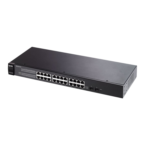
This chapter describes the front panel and rear panel of the Switch and shows you how to make the hardware connections. 3.1 Front Panel The figures below show the front panel of the Switch. Figure 8 GS1510-16 Front Panel RJ-45 Gigabit Ethernet LEDs Figure 9 GS1510-24 Front Panel... -
Page 28: Ethernet Ports
Ethernet switches. (GS1510-24 only) 3.1.1 Ethernet Ports The GS1510-16 has 16 auto-negotiating, auto-crossover RJ-45 Gigabit Ethernet ports. The GS1510-24 has 24 auto-negotiating, auto-crossover RJ-45 Gigabit Ethernet ports. The speed of the Gigabit Ethernet ports can be 10 Mbps, 100Mbps or 1000Mbps and the duplex mode can be half duplex (at 100 Mbps) or full duplex. -
Page 29: Transceiver Installation
Chapter 3 Hardware Overview You can change transceivers while the Switch is operating. You can use different transceivers to connect to Ethernet switches with different types of fiber-optic connectors. • Type: SFP connection interface • Connection speed: 1 Gigabit per second (Gbps) Note: To avoid possible eye injury, do not look into an operating fiber-optic module’s connectors. -
Page 30: The Reset Button
Chapter 3 Hardware Overview Open the transceiver’s latch (latch styles vary). Figure 12 Opening the Transceiver’s Latch Example Pull the transceiver out of the slot. Figure 13 Transceiver Removal Example 3.1.3 The RESET Button Reset the Switch to its factory default configuration via the RESET button. Press the RESET button for at least five seconds and then release. -
Page 31: Rear Panel
3.3 Rear Panel The following figures show the rear panels of the AC power input model Switch. The rear panel contains a receptacle for the power cord. Figure 14 GS1510-16 Rear Panel Figure 15 GS1510-24 Rear Panel 3.3.1 Power Connector Make sure you are using the correct power source as shown on the panel. - Page 32 Chapter 3 Hardware Overview To connect the power to the Switch, insert the female end of the power cord into the power receptacle on the rear panel. Connect the other end of the supplied power cord to a 100~240V AC, 50/60 Hz power outlet capable of supplying at least 0.3A.
-
Page 33: Basic Settings
Basic Settings The Web Configurator (35) System (45) General Settings (47) MAC Management (51) Port Mirroring (55) Port Settings (57) -
Page 35: The Web Configurator
H A P T E R The Web Configurator This section introduces the configuration and functions of the Web Configurator. 4.1 Introduction The Web Configurator is an HTML-based management interface that allows easy setup and management of the Switch via an Internet browser. Use Internet Explorer 6.0 or later to access the web configurator. -
Page 36: Smart Mode
Chapter 4 The Web Configurator Type “http://” and the IP address of the Switch (for example, the default is 192.168.1.1) in the Location or Address field. Press [ENTER]. The login screen appears. The default username is admin and the associated default password is 1234. - Page 37 Chapter 4 The Web Configurator 4.3.1.1 IP Setting The Smart > IP Setting screen is the first screen that displays when you access the Web Configurator. Use this screen to configure the IP address and subnet mask for the Switch. Click Apply to save the changes. Figure 17 Web Configurator Smart Screen IP Setting 4.3.1.2 EEE (Energy Efficient Ethernet) Use this screen to reduce energy consumption over RJ-45 Ethernet Ports during...
- Page 38 Chapter 4 The Web Configurator 4.3.1.3 Web Authentication Click the Web Authentication tab to open the screen as shown next. This feature is used to authenticate users before they access a website on the Internet. Use the ON or OFF button on this screen to globally enable/disable web authentication across all ports.
- Page 39 Chapter 4 The Web Configurator Click Apply to save any changes. Figure 20 Web Configuration Smart Screen - DHCP Snooping 4.3.1.5 STP (Spanning Tree Protocol) Use this screen to activate the Spanning Tree Protocol (STP) feature which is used to prevent loops in the core of your network. Click the STP tab to open the screen as shown next.
-
Page 40: The Advanced Main Screen
Chapter 4 The Web Configurator 4.3.2 The Advanced Main Screen Click Advance to display the following screen that shows the main navigating components of the Web Configurator screen. Figure 22 Web Configurator Advanced Screens (System Information) A - The device graphic displays the status of the ports. B - Use the About link to view more information about the device’s vendor. - Page 41 Chapter 4 The Web Configurator The following table describes the links in the navigation panel. Table 3 Navigation Panel Links LINK DESCRIPTION System Status System Use these screens to view general system information such as firmware Information version, IP address and so on. Basic Settings General Settings Use these screens to configure the system name, IP address, maximum frame size, and system time settings.
-
Page 42: Change Your Password
Chapter 4 The Web Configurator Table 3 Navigation Panel Links (continued) LINK DESCRIPTION 802.1x Use this screen to configure 802.1x authentication method. This method uses an authentication server (RADIUS server) to validate access to a port based on a username and password provided by the user. -
Page 43: Saving Your Configuration
Chapter 4 The Web Configurator 4.4 Saving Your Configuration When you are done modifying the settings in a screen, click Apply to save your changes back to the Switch. 4.5 Switch Lockout You could block yourself (and all others) from using the Web Configurator if you: Remove all the ports from the default VLAN (default is VLAN 1) when no other VLANs exist. -
Page 44: Logging Out Of The Web Configurator
Chapter 4 The Web Configurator 4.7 Logging Out of the Web Configurator Click Logout on the top right corner of the screen to exit the Web Configurator. You have to log in with your password again after you log out. This is recommended after you finish a management session for security reasons. -
Page 45: System
H A P T E R System This chapter describes the system screens. 5.1 System Screen The home screen of the Web Configurator displays general system information. Click System Status > System Information in the navigation panel to view device specific information such as host name, firmware version and so on. Figure 25 System The following table describes the labels in this screen. - Page 46 Chapter 5 System Table 4 System (continued) LABEL DESCRIPTION Firmware This field displays the version number of the Switch's current firmware. Version Click Upgrade to go to the firmware upgrade screen. See Section 21.3.2 on page 131. Built Date This field displays the date of the currently installed firmware. DHCP Client This field displays whether the DHCP client feature is enabled or disabled.
-
Page 47: General Settings
H A P T E R General Settings This chapter describes the General Settings screens in the Basic Settings menu. 6.1 What You Can Do • Use the System screen (Section 6.2 on page 47) to configure the basic IP address settings for the Switch. -
Page 48: Jumbo Frame
Chapter 6 General Settings The following table describes the labels in this screen. Table 5 System Settings LABEL DESCRIPTION Hostname Enter up to 16 alphanumeric characters for the name of your Switch. Hyphens (-) and underscores (_) are also allowed. DHCP Client Select Enable to allow the Switch to automatically get an IP address from a DHCP server. -
Page 49: Sntp
Chapter 6 General Settings Table 6 Basic Settings > General Settings > Jumbo Frame (continued) LABEL DESCRIPTION Apply Click Apply to save your changes back to the Switch. Refresh Click Refresh to begin configuring this screen afresh. 6.4 SNTP Use this screen to configure system date and time. Click Basic Settings > General Settings >... - Page 50 Chapter 6 General Settings Table 7 Basic Settings > General Settings > SNTP (continued) LABEL DESCRIPTION Enable Select this option to use Network Time Protocol (NTP) for the time Network Time service. Protocol NTP Server Select a pre-designated time server or type the IP address of your time server.
-
Page 51: Mac Management
H A P T E R MAC Management 7.1 Overview Use these screens to add, delete and view entries in the MAC address table. The MAC Table (a MAC table is also known as a filtering database) shows how frames are forwarded or filtered across the Switch’s ports. When a device (which may belong to a VLAN group) sends a packet which is forwarded to a port on the Switch, the MAC address of the device is shown on the Switch’s MAC Table. -
Page 52: Static Mac Settings
Chapter 7 MAC Management • If the Switch has not already learned the port for this MAC address, then the frame is flooded to all ports. Too much port flooding leads to network congestion. • If the Switch has already learned the port for this MAC address, but the destination port is the same as the port it came in on, then it filters the frame. -
Page 53: Mac Table
Chapter 7 MAC Management The following table describes the labels in this screen. Table 8 Static MAC Settings LABEL DESCRIPTION Static MAC Settings MAC Address Enter the MAC address of a computer or device that you want to add to the MAC address table. - Page 54 Chapter 7 MAC Management The following table describes the labels in this screen. Table 9 MAC Table LABEL DESCRIPTION Show Type Select Static, Dynamic, or All and then click Apply to display the corresponding MAC address entries on this screen. Apply Refresh Click this to update the information in the MAC table.
-
Page 55: Port Mirroring
H A P T E R Port Mirroring This chapter discusses port mirroring. 8.1 Port Mirroring Settings Port mirroring allows you to copy traffic flow to a monitor port (the port you copy the traffic to) in order that you can examine the traffic from the mirrored port without interference. - Page 56 Chapter 8 Port Mirroring The following table describes the labels in this screen. Table 10 Port Mirroring LABEL DESCRIPTION State Select Enabled to turn on port mirroring or select Disabled to turn it off. Monitor Select the ports for which you want to monitor the traffic. to Port All Ports Settings in this field apply to all ports.
-
Page 57: Port Settings
H A P T E R Port Settings This chapter describes how to view and configure the port settings on the Switch. 9.1 Port Settings Use this screen to configure and view Switch port settings. Click Basic Settings > Port Settings to display the following screen. 9.1.1 Auto Negotiation Auto (auto-negotiation) allows one port to negotiate with a peer port automatically to obtain the connection speed and duplex mode that both ends... - Page 58 Chapter 9 Port Settings Back Pressure flow control is typically used in half duplex mode to send a "collision" signal to the sending port (mimicking a state of packet collision) causing the sending port to temporarily stop sending signals and resend later. Figure 33 Port Settings GS1510 Series User’s Guide...
- Page 59 Chapter 9 Port Settings The following table describes the labels in this screen. Table 11 Port Settings LABEL DESCRIPTION Port Settings Port Select a port number you want to configure on this screen. State Select Enable to activate the port or Disable to deactivate the port. Speed/Duplex Select the speed and duplex mode of the port.
- Page 60 Chapter 9 Port Settings GS1510 Series User’s Guide...
-
Page 61: Advanced Settings
Advanced Settings VLAN (63) EEE (71) IGMP Snooping (73) Link Aggregation (77) Loop Guard (81) QoS (85) Storm Control (93) Spanning Tree Protocol (95) -
Page 63: Vlan
H A P T E R VLAN 10.1 Overview This chapter shows you how to configure IEEE 802.1Q tagged VLANs and port- based VLANs. 10.2 What You Can Do • Use the Port Isolation screen (Section 10.4 on page 64) to specify which ports can communicate with each other. -
Page 64: Forwarding Tagged And Untagged Frames
Chapter 10 VLAN The CFI (Canonical Format Indicator) is a single-bit flag, always set to zero for Ethernet switches. If a frame received at an Ethernet port has a CFI set to 1, then that frame should not be forwarded as it is to an untagged port. The remaining twelve bits define the VLAN ID, giving a possible maximum number of 4,096 VLANs. - Page 65 Chapter 10 VLAN Click Advanced Settings > VLAN > Port Isolation to display the following screen. Figure 34 Port Isolation GS1510 Series User’s Guide...
- Page 66 Chapter 10 VLAN The following table describes the labels in this screen. Table 12 Port Isolation LABEL DESCRIPTION Port Select a port number to configure its port isolation settings. Select All Ports to configure the port isolation settings for all ports on the Switch.
-
Page 67: Vlan Settings
Chapter 10 VLAN 10.5 VLAN Settings Use this screen to configure a static VLAN and assign member ports to it. Click Advanced Settings > VLAN > VLAN > VLAN Settings to display the following screen. Figure 35 VLAN Settings The following table describes the labels in this screen. Table 13 VLAN Settings LABEL DESCRIPTION... -
Page 68: Tag Settings
Chapter 10 VLAN 10.6 Tag Settings Use this screen to tag any outgoing frames from a port with its assigned VLAN ID. You must first configure a VLAN (Section 10.5 on page 67) before using this screen. Click Advanced Settings > VLAN > VLAN > Tag Settings to display the following screen. -
Page 69: Port Settings
Chapter 10 VLAN 10.7 Port Settings Use this screen to configure the VLAN port settings. Click Advanced Settings > VLAN > VLAN > Port Settings to display the following screen. Figure 37 Port Settings The following table describes the labels in this screen. Table 15 Port Settings LABEL DESCRIPTION... - Page 70 Chapter 10 VLAN Table 15 Port Settings (continued) LABEL DESCRIPTION Port This field displays the port number. PVID This field displays the Port VLAN ID number. Acceptable This field displays the type of frames allowed on the port. This will either Frame display All or Tag Only.
-
Page 71: Eee
H A P T E R 11.1 Overview This chapter explains the EEE (Energy Efficient Ethernet) screen. Use this screen to reduce energy consumption over RJ-45 Ethernet Ports during idle periods. The hardware devices connected to the ports must also support EEE for this function to work. - Page 72 Chapter 11 EEE Table 16 EEE (continued) LABEL DESCRIPTION Apply Click this to save any changes to the Switch. Refresh Click this to reload the screen and reset any changes that were just made. GS1510 Series User’s Guide...
-
Page 73: Igmp Snooping
H A P T E R IGMP Snooping 12.1 Overview This chapter shows you how to configure IGMP snooping for multicast traffic. The Switch can passively snoop on IGMP packets transferred between IP multicast routers/switches and IP multicast hosts to learn the IP multicast group membership. -
Page 74: Igmp Snooping And Vlans
Chapter 12 IGMP Snooping 12.3.1 IGMP Snooping and VLANs The Switch can perform IGMP snooping on up to 4094 VLANs. You can configure the Switch to automatically learn multicast group membership of any VLANs. The Switch then performs IGMP snooping on the first VLANs that send IGMP packets. This is referred to as auto mode. -
Page 75: Port Settings
Chapter 12 IGMP Snooping Table 17 IGMP Snooping (continued) LABEL DESCRIPTION IGMP Snooping This field displays whether IGMP snooping is globally enabled or State disabled. IGMP Snooping This field displays VLANs on which the Switch is to perform IGMP VLAN State snooping. - Page 76 Chapter 12 IGMP Snooping GS1510 Series User’s Guide...
-
Page 77: Link Aggregation
H A P T E R Link Aggregation 13.1 Overview This chapter shows you how to logically aggregate physical links to form one logical, higher-bandwidth link. 13.2 What You Can Do • Use the Static Trunk screen (Section 13.4 on page 78) to aggregate groups of physical ports into one higher capacity link. -
Page 78: Static Trunk
Chapter 13 Link Aggregation The IEEE 802.3ad standard describes the Link Aggregation Control Protocol (LACP) for dynamically creating and managing trunk groups. When you enable LACP link aggregation on a port, the port can automatically negotiate with the ports at the remote end of a link to establish trunk groups. LACP also allows port redundancy, that is, if an operational port fails, then one of the “standby”... -
Page 79: Lacp
Chapter 13 Link Aggregation The following table describes the labels in this screen. Table 19 Static Trunk LABEL DESCRIPTION Group State Select the group ID to use for this trunk group, that is, one logical link containing multiple ports. Select Enable to use this static trunk group. Member Select the ports to be added to the static trunk group. - Page 80 Chapter 13 Link Aggregation The following table describes the labels in this screen. Table 20 LACP LABEL DESCRIPTION State Select Enable from the drop down box to enable Link Aggregation Control Protocol (LACP). Select Disable to not use LACP. System LACP system priority is a number between 1 and 65,535.
-
Page 81: Loop Guard
H A P T E R Loop Guard 14.1 Overview Use the Loop Guard screen (Section 14.3 on page 83) to configure the Switch to guard against loops on the edge of your network. Loop guard allows you to configure the Switch to shut down a port if it detects that packets sent out on that port loop back to the Switch. - Page 82 Chapter 14 Loop Guard • It will receive broadcast messages sent out from the switch in loop state. • It will receive its own broadcast messages that it sends out as they loop back. It will then re-broadcast those messages again. The following figure shows port N on switch A connected to switch B.
-
Page 83: Loop Guard
Chapter 14 Loop Guard 14.3 Loop Guard Use this screen to enable the loop guard feature and to configure the port recovery time for when a port goes down. Click Advanced Settings > Loop Guard to display the screen as shown. Figure 46 Loop Guard The following table describes the labels in this screen. - Page 84 Chapter 14 Loop Guard Table 21 Loop Guard (continued) LABEL DESCRIPTION Loop This field displays if the loop recovery feature is enabled. Recovery Recovery This field displays the recovery time for the loop recovery feature. Time (min) GS1510 Series User’s Guide...
-
Page 85: Qos
H A P T E R 15.1 Overview This chapter introduces the quality of service (QoS) parameters you can configure on the Switch. QoS is used to help solve performance degradation when there is network congestion. The Switch allows you to use IEEE 802.1p priority tags or Differentiated Services Code Points (DSCPs) tags to prioritize traffic. -
Page 86: Qos Enhancement
Chapter 15 QoS 15.3.1.1 Weighted Round Robin (WRR) Round Robin scheduling services queues on a rotating basis and is activated only when a port has more traffic than it can handle. A queue is given an amount of bandwidth irrespective of the incoming traffic on that port. This queue then moves to the back of the list. -
Page 87: Ip Diffserv (Dscp)
Chapter 15 QoS received port of the Switch. Click Advanced Settings > QoS > Port Priority to open the following screen. Figure 47 Port Priority The following table describes the labels in this screen. Table 22 Port Priority LABEL DESCRIPTION All Ports Use this field to set a priority for all ports. -
Page 88: Differentiated Services Code Point (Dscp)
Chapter 15 QoS Switch to prioritize all incoming traffic. Click Advanced Settings > QoS > IP DiffServ (DSCP) to open the screen. 15.5.1 Differentiated Services Code Point (DSCP) Differentiated Services (DiffServ) is a class of service (CoS) model that marks packets so that they receive specific per-hop treatment at DiffServ-compliant network devices along the route based on the application types and traffic flow. -
Page 89: Priority/Queue Mapping
Chapter 15 QoS The following table describes the labels in this screen. Table 23 IP DiffServ (DSCP) LABEL DESCRIPTION Mode Select Tag Over DSCP if you want to use 802.1p Priority in packets to prioritize traffic. Select DSCP Over Tag if you want to use DSCP priority to prioritize traffic, even if the packet has an IEEE 802.1p priority tag. -
Page 90: Queuing Method
Chapter 15 QoS The following table describes the labels in this screen. Table 24 Priority/Queue Mapping LABEL DESCRIPTION Reset to Click this button to reset the priority to queue mappings to the defaults. default Priority This field displays each priority level. The values range from 0 (lowest priority) to 7 (highest priority). - Page 91 Chapter 15 QoS The following table describes the labels in this screen. Table 25 Queuing Method LABEL DESCRIPTION Select Weighted Fair Queuing (WFQ), Strict Priority (SP) or Weighted Method Round Robin (WRR). Note: Queue weights can only be changed when Weighted Round Robin is selected.
- Page 92 Chapter 15 QoS GS1510 Series User’s Guide...
-
Page 93: Storm Control
H A P T E R Storm Control This chapter shows you how you can manage bandwidth on each port and set up broadcast storm control settings using the Storm Control screen. 16.0.1 Broadcast Storm Control Setup Broadcast storm control limits the number of broadcast, multicast and unknown unicast (also referred to as Destination Lookup Failure or DLF) packets the Switch receives per second on the ports. - Page 94 Chapter 16 Storm Control The following table describes the labels in this screen. Table 26 Broadcast Storm Control LABEL DESCRIPTION Storm Control Settings Port Select the port number for which you want to configure storm control settings. Rate Select the number of packets (of the type specified in the Type field) per second the Switch can receive per second.
-
Page 95: Spanning Tree Protocol
H A P T E R Spanning Tree Protocol 17.1 Overview (R)STP detects and breaks network loops and provides backup links between switches, bridges or routers. It allows a Switch to interact with other (R)STP- compliant switches in your network to ensure that only one path exists between any two stations on the network. -
Page 96: Stp Terminology
Chapter 17 Spanning Tree Protocol 17.3.1 STP Terminology The root bridge is the base of the spanning tree. Path cost is the cost of transmitting a frame onto a LAN through that port. The recommended cost is assigned according to the speed of the link to which a port is attached. -
Page 97: General Settings
Chapter 17 Spanning Tree Protocol 17.4 General Settings Use this screen to enable and configure the STP settings. Click Advanced Settings > STP > General Settings to see the screen as shown. Figure 52 General Settings The following table describes the labels in this screen. Table 28 General Settings LABEL DESCRIPTION... -
Page 98: Stp Status Screen
Chapter 17 Spanning Tree Protocol Table 28 General Settings (continued) LABEL DESCRIPTION Priority Priority is used in determining the root switch, root port and designated port. The switch with the highest priority (lowest numeric value) becomes the STP root switch. If all switches have the same priority, the switch with the lowest MAC address will then become the root switch. - Page 99 Chapter 17 Spanning Tree Protocol Table 29 STP Status (continued) LABEL DESCRIPTION Hello Time This is the time interval (in seconds) at which the root switch transmits a configuration message. The root bridge determines Hello Time, Max Age and Forwarding Delay. Forward Delay This is the time (in seconds) the root switch will wait before changing states.
- Page 100 Chapter 17 Spanning Tree Protocol GS1510 Series User’s Guide...
-
Page 101: Security And Management
Security and Management IP Source Guard (103) 802.1x (117) Web Authentication (123) Maintenance (129) SNMP (135) User Account (143) -
Page 103: Ip Source Guard
H A P T E R IP Source Guard 18.1 Overview Use the IP source guard screens to filter unauthorized DHCP and ARP packets in your network. IP source guard uses a binding table to distinguish between the authorized and unauthorized DHCP and ARP packets in your network. 18.2 What You Can Do •... -
Page 104: Dhcp Snooping Overview
Chapter 18 IP Source Guard IP source guard consists of the following features: • DHCP snooping. Use this to filter unauthorized DHCP packets on the network and to build the binding table dynamically. • ARP inspection. Use this to filter unauthorized ARP packets on the network. •... -
Page 105: Configuring Dhcp Snooping
Chapter 18 IP Source Guard 18.3.1.3 Configuring DHCP Snooping Follow these steps to configure DHCP snooping on the Switch. Enable DHCP snooping on the Switch. Enable DHCP snooping on each VLAN. Configure trusted and untrusted ports. Configure static bindings. 18.3.2 ARP Inspection Overview Use ARP inspection to filter unauthorized ARP packets on the network. -
Page 106: Configuring Arp Inspection
Chapter 18 IP Source Guard These MAC address filters are different than regular MAC address filters. • They are stored only in volatile memory. • They do not use the same space in memory that regular MAC address filters use. •... -
Page 107: Dhcp Snooping
Chapter 18 IP Source Guard 18.4 DHCP Snooping Use this screen to enable and configure the settings for DHCP Snooping which is used to filter unauthorized DHCP packets on the network. To open this screen, click Security > IP Source Guard > DHCP Snooping > DHCP Snooping. Figure 55 DHCP Snooping The following table describes the labels in this screen. -
Page 108: Port Settings
Chapter 18 IP Source Guard Table 30 DHCP Snooping (continued) LABEL DESCRIPTION Server Ports Select the ports that are connected to DHCP servers or other Switches and deselect the ports which are not. Server ports are connected to DHCP servers or other switches, and the Switch discards DHCP packets from trusted ports only if the rate at which DHCP packets arrive is too high. - Page 109 LABEL DESCRIPTION Port Settings Port Select a port number (1-16 for GS1510-16, 1-26 for GS1510-24) to modify its maximum host count. Maximum Host Count Enter the maximum number of hosts (1-32) that are permitted to simultaneously connect to a port.
-
Page 110: Arp Inspection
Chapter 18 IP Source Guard 18.6 ARP Inspection Use this screen to enable/disable ARP Inspection. You can also use this screen to specify whether ports are trusted or untrusted and which VLANs are enabled for ARP inspection. To open this screen, click Security > IP Source Guard > ARP Inspection > ARP Inspection. -
Page 111: Filter Table
Chapter 18 IP Source Guard Table 32 ARP Inspection (continued) LABEL DESCRIPTION Deselect All Click this to set all ports to untrusted. Apply Click this to save any changes to the Switch. Refresh Click this to reload the screen and reset any changes that were just made. -
Page 112: Binding Table
Chapter 18 IP Source Guard The following table describes the labels in this screen. Table 33 Filter Table LABEL DESCRIPTION Filter Age Time This setting has no effect on existing MAC address filters. Enter how long (1-10080 minutes) the MAC address filter remains in the Switch after the Switch identifies an unauthorized ARP packet. - Page 113 Chapter 18 IP Source Guard To open this screen, click Security > IP Source Guard > Binding Table > Static Entry Settings. Figure 59 Static Entry Settings The following table describes the labels in this screen. Table 34 Static Entry Settings LABEL DESCRIPTION MAC Address...
-
Page 114: Binding Table
Chapter 18 IP Source Guard 18.7.2 Binding Table Use this screen to look at the current bindings. You can also use this screen to convert dynamic binding entries to static entries by selecting the entries and clicking Apply. Bindings are used by DHCP snooping and ARP inspection to distinguish between authorized and unauthorized packets in the network. - Page 115 Chapter 18 IP Source Guard Table 35 Binding Table (continued) LABEL DESCRIPTION Type This field displays how the Switch learned the binding. Static: This binding was learned from information provided manually by an administrator. Dynamic: This binding was learned by snooping DHCP packets. Apply Click Apply and the Switch will convert any selected dynamic binding entries to static entries.
- Page 116 Chapter 18 IP Source Guard GS1510 Series User’s Guide...
-
Page 117: 117
H A P T E R 802.1x This chapter describes the IEEE 802.1x screens. 19.1 Overview Port authentication is a way to validate access to ports on the Switch to clients based on a local or external server (authentication server). The Switch supports the following method for port authentication: •... -
Page 118: What You Need To Know
Chapter 19 802.1x 19.3 What You Need to Know 19.3.1 IEEE 802.1x Authentication The following figure illustrates how a client connecting to a IEEE 802.1x authentication enabled port goes through a validation process. The Switch prompts the client for login information in the form of a user name and password. When the client provides the login credentials, the Switch sends an authentication request to a RADIUS server. - Page 119 Chapter 19 802.1x To open the screen as shown, click Security > 802.1x > Global Settings. Figure 62 Global Settings The following table describes the labels in this screen. Table 36 Global Settings LABEL DESCRIPTION State Select Enable to permit 802.1x authentication on the Switch. Note: You must first enable 802.1x authentication on the Switch before configuring it on each port.
-
Page 120: Port Settings
Chapter 19 802.1x Table 36 Global Settings (continued) LABEL DESCRIPTION Global Status State This field displays if 802.1x authentication is Enabled or Disabled. Authentication This field displays if the authentication method is Local or RADIUS. Method Primary Radius This field displays the IP address, UDP port and shared key for the Server Primary Radius Server. - Page 121 Chapter 19 802.1x The following table describes the labels in this screen. Table 37 Port Settings LABEL DESCRIPTION Port Select a port number to configure. 802.1x State Select Enable to permit 802.1x authentication on the port. You must first enable 802.1x authentication on the Switch before configuring it on each port.
- Page 122 Chapter 19 802.1x Table 37 Port Settings (continued) LABEL DESCRIPTION Admin Control This field displays the Admin Control Direction. Direction Both will drop incoming and outgoing packets on the port when a user has not passed 802.1x port authentication. In will drop only incoming packets on the port when a user has not passed 802.1x port authentication.
-
Page 123: Web Authentication
H A P T E R Web Authentication 20.1 Overview This feature is used to authenticate users before they can access a website on the Internet. The Switch can authenticate users who try to log in based on user accounts configured on the Switch itself (see Section 23.2 on page 143). -
Page 124: User Authentication Experience
Chapter 20 Web Authentication When a device using that port attempts to connect to the Internet, the web browser will request a username and password before allowing access. If a port is not successfully authenticated, all IP packets from that device will be filtered. Note: The URL entered by the user should be a domain such as http:// news.zyxel.com, it cannot be in one of the formats listed below: •... -
Page 125: Configuration
Chapter 20 Web Authentication 20.4 Configuration Use the Configuration screen to enable or disable the Web Authentication feature. You can also use this screen to configure the authentication method. Note: Another version of this screen can be accessed in Smart Mode. See Section 4.3.1.3 on page 38 for more details. -
Page 126: Customization
Chapter 20 Web Authentication The following table describes the labels in this screen. Table 38 Configuration LABEL DESCRIPTION State Select Enable to use the web authentication feature. Method Select whether to use Local or RADIUS as the authentication method. The Local method of authentication uses the user and guest user groups of the user account database on the Switch to authenticate. - Page 127 Chapter 20 Web Authentication Click Security > Web Authentication > Customization to open the following screen. Figure 67 Customization The following table describes the labels in this screen. Table 39 Customization LABEL DESCRIPTION Upload Logo Enter or browse to the location of a suitable image file (GIF/PNG/JPG/ File BMP) of no greater size than 220 x 74 pixels and click Upload.
- Page 128 Chapter 20 Web Authentication Table 39 Customization (continued) LABEL DESCRIPTION Color Enter the HTML code for the color of the Background or pick one from the swatch palette icon. Apply Click this to save any changes. Reset Click this to reset any changes that were made. Preview Click this to update the demonstration of the login page.
-
Page 129: Maintenance
H A P T E R Maintenance 21.1 Overview This chapter explains how to configure the maintenance screens that let you maintain the firmware and configuration files. 21.2 What You Can Do • Use the Configuration screen (Section 21.3 on page 130) to manage the configuration settings. -
Page 130: Configuration
Chapter 21 Maintenance 21.3 Configuration Use this screen to manage configuration files. Click Management > Maintenance > Configuration to open the following screen. Figure 68 Configuration 21.3.1 Backup Settings Backing up your Switch configurations allows you to create various “snap shots” of your device from which you may restore at a later date. -
Page 131: Upgrade Configuration
Chapter 21 Maintenance 21.3.2 Upgrade Configuration Restore a previously saved configuration from your computer to the Switch. Figure 70 Upgrade Configuration Type the path and file name of the configuration file you wish to restore in the File path text box or click Browse to display the Choose file screen from which you can locate it. -
Page 132: Firmware
Chapter 21 Maintenance 21.4 Firmware Make sure you have downloaded (and unzipped) the correct model firmware and version to your computer before uploading to the device. Be sure to upload the correct model firmware as uploading the wrong model firmware may damage your device. Click Management >... -
Page 133: System Log
Chapter 21 Maintenance In the Reboot screen, click the Reboot button. The following screen displays. Figure 75 Reboot System Click OK again and then wait for the Switch to restart. This takes up to two minutes. This does not affect the Switch’s configuration. 21.6 System Log Use this screen to view the system logs and to configure an external syslog server. - Page 134 Chapter 21 Maintenance Click Management > Maintenance > System Log to display the screen as shown next. Click Refresh to update the log and see any available new entires. Figure 76 System Log The following table describes the labels in this screen. Table 41 System Log LABEL DESCRIPTION...
-
Page 135: Snmp
H A P T E R SNMP 22.1 Overview This chapter describes how to configure the SNMP options of the Switch. Simple Network Management Protocol (SNMP) is an application layer protocol used to manage and monitor TCP/IP-based devices. 22.2 What You Can Do •... - Page 136 Chapter 22 SNMP next figure illustrates an SNMP management operation. SNMP is only available if TCP/IP is configured. Figure 77 SNMP Management Model An SNMP managed network consists of two main components: agents and a manager. An agent is a management software module that resides in a managed network device (the Switch).
-
Page 137: Supported Mibs
Chapter 22 SNMP 22.3.2 Supported MIBs MIBs let administrators collect statistics and monitor status and performance. The Switch supports the following MIBs: • RFC 1157 SNMP • RFC 1213 SNMP MIB II • MIB II - System • MIB II - Interface •... -
Page 138: Community Name
Chapter 22 SNMP Click Management > SNMP > SNMP Settings to open the screen as shown. Figure 78 SNMP Settings The following table describes the labels in this screen. Table 44 SNMP Settings LABEL DESCRIPTION SNMP State Select Enable to activate SNMP on the Switch. Select Disable to not use SNMP on the Switch. - Page 139 Chapter 22 SNMP SNMP communities act like passwords and are used to define the security parameters of SNMP clients in an SNMP v1 and SNMP v2c environments. The default SNMP community is “public” for both SNMP v1 and SNMP v2c. Figure 79 Community Name The following table describes the labels in this screen.
-
Page 140: Trap Receiver
Chapter 22 SNMP Table 45 Community Name (continued) LABEL DESCRIPTION Rights This field displays the community string’s rights. This will be Read Only or Read Write. Network ID of This field displays the IP address of the remote SNMP management Trusted Host station after it has been modified by the subnet mask. - Page 141 Chapter 22 SNMP Table 46 Trap Receiver (continued) LABEL DESCRIPTION This field displays the index number of the trap receiver entry. Click the number to modify the entry. IP Address This field displays the IP address of the remote trap station. Version This field displays the version of Simple Network Management Protocol in use.
- Page 142 Chapter 22 SNMP GS1510 Series User’s Guide...
-
Page 143: User Account
H A P T E R User Account 23.1 Overview This chapter describes the User Account screen. There are three types of user accounts on the Switch. Admin, User and Guest. • The Admin account is used for administrating the Switch using the web configurator. - Page 144 Chapter 23 User Account Note: You cannot delete the default Admin and Guest accounts. However, you can modify the Guest username and password. Figure 81 User Account The following table describes the labels in this screen. Table 47 User Account LABEL DESCRIPTION User Name...
-
Page 145: Troubleshooting & Product Specifications
Troubleshooting & Product Specifications Troubleshooting (147) Product Specifications (151) -
Page 147: Troubleshooting
H A P T E R Troubleshooting This chapter offers some suggestions to solve problems you might encounter. The potential problems are divided into the following categories. • Power, Hardware Connections, and LEDs • Switch Access and Login 24.1 Power, Hardware Connections, and LEDs The Switch does not turn on. -
Page 148: Switch Access And Login
Chapter 24 Troubleshooting If the problem continues, contact the vendor. 24.2 Switch Access and Login I forgot the IP address for the Switch. The default IP address is 192.168.1.1. If this does not work, you have to reset the device to its factory defaults. See Section 3.3 on page I forgot the username and/or password. - Page 149 Chapter 24 Troubleshooting Reset the device to its factory defaults, and try to access the Switch with the default IP address. See Section 3.3 on page If the problem continues, contact the vendor, or try one of the advanced suggestions. I can see the Login screen, but I cannot log in to the Switch.
- Page 150 Chapter 24 Troubleshooting GS1510 Series User’s Guide...
-
Page 151: Product Specifications
Storage: -40º C ~ 70º C (-40º F ~ 158º F) Humidity 10 ~ 95% (non-condensing) Power Supply GS1510-16: AC: 100 - 240V 50/60Hz 0.3A max internal universal power supply GS1510-24: AC: 100 - 240V 50/60Hz 0.4A max internal universal power supply Power GS1510-16: 18W (maximum) - Page 152 Chapter 25 Product Specifications Table 49 General Product Specifications Interface GS1510-16: 16 1000BASE-T RJ-45 Gigabit Ethernet ports GS1510-24: 24 1000BASE-T RJ-45 Gigabit Ethernet ports For GS1510-24, 2 Mini-GBIC (Small Form-Factor Pluggable (SFP)) slot. Auto-negotiation Auto-MDIX Compliant with IEEE 802.3ad/u/x Back pressure flow control for half duplex Flow control for full duplex (IEEE 802.3x)
- Page 153 Chapter 25 Product Specifications Table 50 Management Specifications System Control LED indication for power status Performance monitoring Line speed Four RMON groups (history, statistics, alarms, and events) Port mirroring and aggregation Firmware upgrade and download through HTTP Reset to default button Network Web-based management Management...
- Page 154 Chapter 25 Product Specifications Table 51 Firmware Features FEATURE DESCRIPTION Port Mirroring Port mirroring allows you to copy traffic going from one or all ports to another or all ports in order that you can examine the traffic from the mirror port (the port you copy the traffic to) without interference.
- Page 155 Chapter 25 Product Specifications Table 52 Standards Supported (continued)(IEEE) STANDARD DESCRIPTION IEEE 802.1p Class of Service, Priority protocols IEEE 802.1Q Tagged VLAN IEEE 802.1X Port Authentication IEEE 802.3ad LACP Aggregation Table 53 Standards Supported (RFC) STANDARD DESCRIPTION RFC 826 Address Resolution Protocol (ARP) RFC 1112 IGMP v1 RFC 1157...
- Page 156 Chapter 25 Product Specifications GS1510 Series User’s Guide...
-
Page 157: Appendices And Index
Appendices and Index Device Auto Discovery (159) IP Addresses and Subnetting (165) Legal Information (175) Index (199) -
Page 159: Appendix A Device Auto Discovery
P P E N D I X Device Auto Discovery This appendix introduces the ZyXEL device discovery utility. This utility helps the network administrator find the IP address of a device on the network by performing a scan. This function is useful if the default IP address has been changed and the device can not be located on the network, this utility is even more useful if the Switch does not have a console port. - Page 160 Appendix A Device Auto Discovery After reading the license agreement, select I accept the agreement and click Next. Choose the location in which to install the program files to. The default location is C:\Program Files\ZyXEL Device Discovery. Click Next to continue the installation. Select the components to install, ZyXEL Device Discovery 1.0 is mandatory.
- Page 161 Appendix A Device Auto Discovery Select if you want to create an icon for the program on your desktop and click Next to continue the installation. Confirm the installation settings you have just configured and click Install to start the installation. To change an installation setting, click Back. GS1510 Series User’s Guide...
- Page 162 Appendix A Device Auto Discovery A progress bar will display as the software is being installed. After the installation has finished, select whether to launch the utility now or later and click Finish to complete the setup process. GS1510 Series User’s Guide...
-
Page 163: Using The Software
Appendix A Device Auto Discovery Using the Software After launching the utility, the following screen will display. To begin scanning for devices on the network you are currently connected to, click the Search button. You can also configure a more specific search by selecting to search only for devices with a specific model name. - Page 164 Appendix A Device Auto Discovery After performing a search on the network, some results will display in the table. When you have located the device you are looking for, double-click anywhere within the row to launch the device’s web configurator in your browser. If there are too many devices on the network, you can use the Filter drop-down box to narrow down the results.
-
Page 165: Appendix B Ip Addresses And Subnetting
P P E N D I X IP Addresses and Subnetting This appendix introduces IP addresses and subnet masks. IP addresses identify individual devices on a network. Every networking device (including computers, servers, routers, printers, etc.) needs an IP address to communicate across the network. -
Page 166: Subnet Masks
Appendix B IP Addresses and Subnetting The following figure shows an example IP address in which the first three octets (192.168.1) are the network number, and the fourth octet (16) is the host ID. Figure 84 Network Number and Host ID How much of the IP address is the network number and how much is the host ID varies according to the subnet mask. - Page 167 Appendix B IP Addresses and Subnetting Table 54 Subnet Mask Example OCTET: OCTET: OCTET: OCTET (192) (168) Network Number 11000000 10101000 00000001 Host ID 00000010 By convention, subnet masks always consist of a continuous sequence of ones beginning from the leftmost bit of the mask, followed by a continuous sequence of zeros, for a total number of 32 bits.
- Page 168 Appendix B IP Addresses and Subnetting As these two IP addresses cannot be used for individual hosts, calculate the maximum number of possible hosts in a network as follows: Table 56 Maximum Host Numbers MAXIMUM NUMBER OF SUBNET MASK HOST ID SIZE HOSTS 8 bits 255.0.0.0...
- Page 169 Appendix B IP Addresses and Subnetting In this example, the company network address is 192.168.1.0. The first three octets of the address (192.168.1) are the network number, and the remaining octet is the host ID, allowing a maximum of 2 –...
- Page 170 Appendix B IP Addresses and Subnetting The following figure shows the company network after subnetting. There are now two sub-networks, A and B. Figure 86 Subnetting Example: After Subnetting In a 25-bit subnet the host ID has 7 bits, so each sub-network has a maximum of –...
- Page 171 Appendix B IP Addresses and Subnetting Each subnet contains 6 host ID bits, giving 2 - 2 or 62 hosts for each subnet (a host ID of all zeroes is the subnet itself, all ones is the subnet’s broadcast address). Table 58 Subnet 1 LAST OCTET BIT IP/SUBNET MASK...
- Page 172 Appendix B IP Addresses and Subnetting Example: Eight Subnets Similarly, use a 27-bit mask to create eight subnets (000, 001, 010, 011, 100, 101, 110 and 111). The following table shows IP address last octet values for each subnet. Table 62 Eight Subnets SUBNET LAST BROADCAST...
-
Page 173: Configuring Ip Addresses
Appendix B IP Addresses and Subnetting Table 64 16-bit Network Number Subnet Planning (continued) NO. “BORROWED” NO. HOSTS PER SUBNET MASK NO. SUBNETS HOST BITS SUBNET 255.255.224.0 (/19) 8190 255.255.240.0 (/20) 4094 255.255.248.0 (/21) 2046 255.255.252.0 (/22) 1022 255.255.254.0 (/23) 255.255.255.0 (/24) 255.255.255.128 (/25) 255.255.255.192 (/26) - Page 174 Appendix B IP Addresses and Subnetting Private IP Addresses Every machine on the Internet must have a unique address. If your networks are isolated from the Internet (running only between two branch offices, for example) you can assign any IP addresses to the hosts without problems. However, the Internet Assigned Numbers Authority (IANA) has reserved the following three blocks of IP addresses specifically for private networks: •...
-
Page 175: Appendix C Legal Information
ZyXEL Communications Corporation. Published by ZyXEL Communications Corporation. All rights reserved. Disclaimer ZyXEL does not assume any liability arising out of the application or use of any products, or software described herein. - Page 176 Appendix C Legal Information • This device must accept any interference received, including interference that may cause undesired operations. FCC Warning This device has been tested and found to comply with the limits for a Class A digital switch, pursuant to Part 15 of the FCC Rules. These limits are designed to provide reasonable protection against harmful interference in a commercial environment.
-
Page 177: Zyxel Limited Warranty
Appendix C Legal Information Viewing Certifications Go to http://www.zyxel.com. Select your product on the ZyXEL home page to go to that product's page. Select the certification you wish to view from this page. ZyXEL Limited Warranty ZyXEL warrants to the original end user (purchaser) that this product is free from any defects in materials or workmanship for a period of up to two years from the date of purchase. - Page 178 Appendix C Legal Information GS1510 Series User’s Guide...
-
Page 179: Appendix D Open Software Announcements
Open Software Announcements End-User License Agreement for “GS1510-16/GS1510-24” WARNING: ZyXEL Communications Corp. IS WILLING TO LICENSE THE SOFTWARE TO YOU ONLY UPON THE CONDITION THAT YOU ACCEPT ALL OF THE TERMS CONTAINED IN THIS LICENSE AGREEMENT. PLEASE READ THE TERMS CAREFULLY BEFORE COMPLETING THE INSTALLATION PROCESS AS INSTALLING THE SOFTWARE WILL INDICATE YOUR ASSENT TO THEM. - Page 180 Appendix D Open Software Announcements hereunder. Any rights not expressly granted by ZyXEL to you are reserved by ZyXEL, and all implied licenses are disclaimed. 2.Ownership You have no ownership rights in the Software. Rather, you have a license to use the Software as long as this License Agreement remains in full force and effect.
- Page 181 Appendix D Open Software Announcements 5.Confidentiality You acknowledge that the Software contains proprietary trade secrets of ZyXEL and you hereby agree to maintain the confidentiality of the Software using at least as great a degree of care as you use to maintain the confidentiality of your own most confidential information.
- Page 182 Appendix D Open Software Announcements 8.Export Restrictions THIS LICENSE AGREEMENT IS EXPRESSLY MADE SUBJECT TO ANY APPLICABLE LAWS, REGULATIONS, ORDERS, OR OTHER RESTRICTIONS ON THE EXPORT OF THE SOFTWARE OR INFORMATION ABOUT SUCH SOFTWARE WHICH MAY BE IMPOSED FROM TIME TO TIME. YOU SHALL NOT EXPORT THE SOFTWARE, DOCUMENTATION OR INFORMATION ABOUT THE SOFTWARE AND DOCUMENTATION WITHOUT COMPLYING WITH SUCH LAWS, REGULATIONS, ORDERS, OR OTHER RESTRICTIONS.
- Page 183 Appendix D Open Software Announcements jurisdiction, the remainder of this License Agreement shall be interpreted so as to reasonably effect the intention of the parties. NOTE: Some components of this product incorporate free software programs covered under the open source code licenses which allows you to freely copy, modify and redistribute the software.
- Page 184 Appendix D Open Software Announcements Preamble The licenses for most software are designed to take away your freedom to share and change it. By contrast, the GNU General Public License is intended to guarantee your freedom to share and change free software--to make sure the software is free for all its users.
- Page 185 Appendix D Open Software Announcements 0. This License applies to any program or other work which contains a notice placed by the copyright holder saying it may be distributed under the terms of this General Public License. The "Program", below, refers to any such program or work, and a "work based on the Program"...
- Page 186 Appendix D Open Software Announcements when you distribute the same sections as part of a whole which is a work based on the Program, the distribution of the whole must be on the terms of this License, whose permissions for other licensees extend to the entire whole, and thus to each and every part regardless of who wrote it.
- Page 187 Appendix D Open Software Announcements from you under this License will not have their licenses terminated so long as such parties remain in full compliance. 5. You are not required to accept this License, since you have not signed it. However, nothing else grants you permission to modify or distribute the Program or its derivative works.
- Page 188 Appendix D Open Software Announcements 9. The Free Software Foundation may publish revised and/or new versions of the General Public License from time to time. Such new versions will be similar in spirit to the present version, but may differ in detail to address new problems or concerns.
- Page 189 Appendix D Open Software Announcements This Product includes net-snmp software under BSD like license. License Various copyrights apply to this package, listed in various separate parts below. Please make sure that you read all the parts. ---- Part 1: CMU/UCD copyright notice: (BSD like) ----- Copyright 1989, 1991, 1992 by Carnegie Mellon University Derivative Work - 1996, 1998-2000 Copyright 1996, 1998-2000 The Regents of the University of California...
- Page 190 Appendix D Open Software Announcements WARRANTIES OF MERCHANTABILITY AND FITNESS. IN NO EVENT SHALL CMU OR THE REGENTS OF THE UNIVERSITY OF CALIFORNIA BE LIABLE FOR ANY SPECIAL,INDIRECT OR CONSEQUENTIAL DAMAGES OR ANY DAMAGES WHATSOEVER RESULTING FROM THE LOSS OF USE, DATA OR PROFITS, WHETHER IN AN ACTION OF CONTRACT, NEGLIGENCE OR OTHER TORTIOUS ACTION, ARISING OUT OF OR IN CONNECTION WITH THE USE OR PERFORMANCE OF THIS SOFTWARE.
- Page 191 Appendix D Open Software Announcements (INCLUDING NEGLIGENCE OR OTHERWISE) ARISING IN ANY WAY OUT OF THE USE OF THIS SOFTWARE, EVEN IF ADVISED OF THE POSSIBILITY OF SUCH DAMAGE. ---- Part 3: Cambridge Broadband Ltd. copyright notice (BSD) ----- Portions of this code are copyright (c) 2001-2003, Cambridge Broadband Ltd. All rights reserved.
- Page 192 Appendix D Open Software Announcements WHETHER IN CONTRACT, STRICT LIABILITY, OR TORT (INCLUDING NEGLIGENCE OR OTHERWISE) ARISING IN ANY WAY OUT OF THE USE OF THIS SOFTWARE, EVEN IF ADVISED OF THE POSSIBILITY OF SUCH DAMAGE. ---- Part 4: Sun Microsystems, Inc. copyright notice (BSD) ----- Copyright ©...
- Page 193 Appendix D Open Software Announcements THIS SOFTWARE IS PROVIDED BY THE COPYRIGHT HOLDERS AND CONTRIBUTORS ``AS IS'' AND ANY EXPRESS OR IMPLIED WARRANTIES, INCLUDING, BUT NOT LIMITED TO, THE IMPLIED WARRANTIES OF MERCHANTABILITY AND FITNESS FOR A PARTICULAR PURPOSE ARE DISCLAIMED. IN NO EVENT SHALL THE COPYRIGHT HOLDERS OR CONTRIBUTORS BE LIABLE FOR ANY DIRECT, INDIRECT, INCIDENTAL, SPECIAL, EXEMPLARY, OR CONSEQUENTIAL DAMAGES (INCLUDING, BUT NOT LIMITED TO, PROCUREMENT...
- Page 194 Appendix D Open Software Announcements THIS SOFTWARE IS PROVIDED BY THE COPYRIGHT HOLDERS AND CONTRIBUTORS ``AS IS'' AND ANY EXPRESS OR IMPLIED WARRANTIES, INCLUDING, BUT NOT LIMITED TO, THE IMPLIED WARRANTIES OF MERCHANTABILITY AND FITNESS FOR A PARTICULAR PURPOSE ARE DISCLAIMED. IN NO EVENT SHALL THE COPYRIGHT HOLDERS OR CONTRIBUTORS BE LIABLE FOR ANY DIRECT, INDIRECT, INCIDENTAL, SPECIAL, EXEMPLARY, OR CONSEQUENTIAL DAMAGES (INCLUDING, BUT NOT LIMITED TO, PROCUREMENT...
- Page 195 Appendix D Open Software Announcements THIS SOFTWARE IS PROVIDED BY THE COPYRIGHT HOLDERS AND CONTRIBUTORS ``AS IS'' AND ANY EXPRESS OR IMPLIED WARRANTIES, INCLUDING, BUT NOT LIMITED TO, THE IMPLIED WARRANTIES OF MERCHANTABILITY AND FITNESS FOR A PARTICULAR PURPOSE ARE DISCLAIMED. IN NO EVENT SHALL THE COPYRIGHT HOLDERS OR CONTRIBUTORS BE LIABLE FOR ANY DIRECT, INDIRECT, INCIDENTAL, SPECIAL, EXEMPLARY, OR CONSEQUENTIAL DAMAGES (INCLUDING, BUT NOT LIMITED TO, PROCUREMENT...
- Page 196 Appendix D Open Software Announcements * The name of Fabasoft R&D Software GmbH & Co KG or any of its subsidiaries, brand or product names may not be used to endorse or promote products derived from this software without specific prior written permission. THIS SOFTWARE IS PROVIDED BY THE COPYRIGHT HOLDER ``AS IS'' AND ANY EXPRESS OR IMPLIED WARRANTIES, INCLUDING, BUT NOT LIMITED TO, THE IMPLIED WARRANTIES OF MERCHANTABILITY AND FITNESS FOR A PARTICULAR...
- Page 197 Appendix D Open Software Announcements THIS SOFTWARE IS PROVIDED BY APPLE AND ITS CONTRIBUTORS "AS IS" AND ANY EXPRESS OR IMPLIED WARRANTIES, INCLUDING, BUT NOT LIMITED TO, THE IMPLIED WARRANTIES OF MERCHANTABILITY AND FITNESS FOR A PARTICULAR PURPOSE ARE DISCLAIMED. IN NO EVENT SHALL APPLE OR ITS CONTRIBUTORS BE LIABLE FOR ANY DIRECT, INDIRECT, INCIDENTAL, SPECIAL, EXEMPLARY, OR CONSEQUENTIAL DAMAGES (INCLUDING, BUT NOT LIMITED TO, PROCUREMENT OF SUBSTITUTE GOODS OR SERVICES;...
- Page 198 Appendix D Open Software Announcements INCLUDING, BUT NOT LIMITED TO, THE IMPLIED WARRANTIES OF MERCHANTABILITY AND FITNESS FOR A PARTICULAR PURPOSE ARE DISCLAIMED. IN NO EVENT SHALL THE COPYRIGHT HOLDERS OR CONTRIBUTORS BE LIABLE FOR ANY DIRECT, INDIRECT, INCIDENTAL, SPECIAL, EXEMPLARY, OR CONSEQUENTIAL DAMAGES (INCLUDING, BUT NOT LIMITED TO, PROCUREMENT OF SUBSTITUTE GOODS OR SERVICES;...
-
Page 199: Index
Index Index change running config configuration file backup alternative subnet mask notation restore applications configuration, saving backbone copyright bridging IEEE 802.1Q VLAN current date switched workgroup current time ARP inspection 104, 105 and MAC filter configuring syslog messages trusted ports daylight saving time auto-crossover ports DHCP snooping... - Page 200 Index firmware upgrade firmware version L2 management front panel LACP system priority layer 2 features LEDs link aggregation dynamic 77, 78 general features Link Aggregation Control Protocol (LACP) general setup 48, 49 Link Aggregation Control Protocol, see LACP GMT (Greenwich Mean Time) lockout login password...
- Page 201 Index mini-GBIC slots connection speed connector type transceiver installation QoS (Quality of Service) transceiver removal Quality of Service, see QoS mirroring ports queue weight monitor port queuing mounting brackets MSA (MultiSource Agreement) multicast queuing method 802.1 priority setup Rapid Spanning Tree Protocol, See RSTP. reboot load configuration network management...
- Page 202 Index time zone network components time service protocol object variables trademarks protocol operations transceiver setup installation traps removal versions supported traps, SNMP SNMP (Simple Network Management Protocol) trunk group trunking 21, 77, 152 SNMP traps configuration 66, 67, 68, 69, 79, 80 SP (Strict Priority) queuing trusted ports Spanning Tree Protocol, See STP.
- Page 203 Index logout navigation 36, 37, 39, 40 weight of the switch weight, queuing Weighted Round Robin scheduling (WRR) WRR (Weighted Round Robin) scheduling GS1510 Series User’s Guide...
- Page 204 Index GS1510 Series User’s Guide...
Need help?
Do you have a question about the GS1510-16 and is the answer not in the manual?
Questions and answers