ZyXEL Communications GS1900 Series User Manual
Gbe smart managed switch
Hide thumbs
Also See for GS1900 Series:
- User manual (272 pages) ,
- Specifications (4 pages) ,
- User manual (245 pages)

Related Manuals for ZyXEL Communications GS1900 Series


Summary of Contents for ZyXEL Communications GS1900 Series
- Page 1 User’s Guide GS1900 Series GbE Smart Managed Switch Version 2.60 Edition 2, 02/2021 Default Login Details IP Address http://192.168.1.1 (In-band ports) User Name admin Password 1234 Copyright © 2021 Zyxel Communications Corporation...
- Page 2 Click the help link for a description of the fields in the Switch menus. • More Information Go to for product discussions. https:/ / b usine ssfo rum .zyxe l.c o m • Go to to find other information on the Switch suppo rt.zyxe l.c o m GS1900 Series User’s Guide...
-
Page 3: Do C Um E Nt C O Nve Ntio Ns
Ic o ns Use d in Fig ure s Figures in this user guide may use the following generic icons. The Switch icon is not an exact representation of your device. Switch Generic Switch Generic Router IP Camera Firewall Cell Tower Printer Server GS1900 Series User’s Guide... -
Page 4: Table Of Contents
Configuration: Time Range Group ....................156 Configuration: Multicast ........................161 Configuration: Spanning Tree ......................169 Configuration: LLDP ..........................178 Configuration: QoS ..........................190 Configuration: Security ........................199 Configuration: AAA ..........................209 Configuration: Management ......................214 Maintenance ............................231 Troubleshooting ..........................243 GS1900 Series User’s Guide... -
Page 5: Table Of Contents
2.5.3 Mounting the Switch on a Rack ..................26 C ha pte r 3 Ha rdwa re O ve rvie w...........................28 3.1 Front Panel Connections ....................... 28 3.1.1 Ethernet Ports ......................... 29 3.1.2 SFP Slots ..........................30 GS1900 Series User’s Guide... - Page 6 Mo nito r: Syste m ..........................64 7.1 Overview ............................64 7.1.1 What You Can Do in this Chapter ..................64 7.2 IP ............................... 64 7.2.1 IPv4 ............................64 7.2.2 IPv6 ............................65 7.3 Information ............................65 GS1900 Series User’s Guide...
- Page 7 11.2 Link Aggregation .......................... 85 C ha pte r 12 Mo nito r: L o o p G ua rd .........................87 12.1 Overview ............................87 12.1.1 What You Can Do in this Chapter ..................88 12.2 Loop Guard ........................... 88 GS1900 Series User’s Guide...
- Page 8 16.3.1 Port ............................105 16.3.2 Authenticated Hosts ......................106 C ha pte r 17 Mo nito r: Ma na g e m e nt ........................107 17.1 Overview ............................. 107 17.1.1 What You Can Do in this Chapter ................... 107 GS1900 Series User’s Guide...
- Page 9 C ha pte r 20 C o nfig ura tio n: VL AN ........................128 20.1 Overview ............................. 128 20.1.1 What You Can Do in this Chapter ................... 128 20.2 VLAN ............................129 20.2.1 The VLAN Screen ....................... 129 GS1900 Series User’s Guide...
- Page 10 22.2.7 The LACP Port Edit Screen ....................149 C ha pte r 23 C o nfig ura tio n: L o o p G ua rd ......................150 23.1 Overview ............................. 150 23.2 Loop Guard ..........................150 GS1900 Series User’s Guide...
- Page 11 27.2.2 The STP Port Screen ......................170 27.2.3 The STP Port Edit Screen ....................171 27.2.4 The CIST Screen ......................... 172 27.2.5 The CIST Port Screen ......................173 27.2.6 The CIST Port Edit Screen ....................173 GS1900 Series User’s Guide...
- Page 12 30.2 Port Security ..........................199 30.2.1 The Global Screen ......................199 30.2.2 The Port Screen ......................... 199 30.2.3 The Port Edit Screen ......................200 30.3 Protected Port ..........................201 30.3.1 The Protected Port Screen ....................201 GS1900 Series User’s Guide...
- Page 13 32.3.4 The Group Screen ......................218 32.3.5 The Group Add Screen ....................219 32.3.6 The User Screen ......................... 220 32.3.7 The User Add Screen ......................221 32.3.8 The Trap Screen ......................... 221 32.3.9 The Trap Destination Screen .................... 222 GS1900 Series User’s Guide...
- Page 14 33.6.2 Reset the Switch to Factory Defaults ................237 33.7 Network Diagnostics ........................238 33.7.1 Port Test ..........................238 33.7.2 IPv4 Ping Test ........................238 33.7.3 IPv6 Ping Test ........................240 33.7.4 Trace Route ........................241 GS1900 Series User’s Guide...
- Page 15 T ro ub le sho o ting ..........................243 34.1 Power, Hardware Connections, and LEDs ................243 34.2 Switch Access and Login ......................244 34.3 Switch Configuration ........................245 Appendix A Customer Support ..................... 246 Appendix B Legal Information ....................... 252 Inde x ..............................259 GS1900 Series User’s Guide...
-
Page 16: Use R's G Uide
A RT Use r’s G uide... -
Page 17: Getting To Know Your Switch
This chapter introduces the main features and applications of the Switch. 1.1 Intro duc tio n The GS1900 series is a new generation Gigabit Ethernet (GbE) Web-Managed Switch. This User’s Guide covers the following models: Table 1 GS1900 Series Comparison Table... -
Page 18: Backbone Example Application
All users that need high bandwidth can connect to high-speed department servers through the Switch. You can provide a super-fast uplink connection by using a Gigabit Ethernet or SFP port on the Switch. GS1900 Series User’s Guide... -
Page 19: Gigabit Ethernet To The Desktop
1.2.5 IEEE 802.1Q VL AN Applic a tio n Exa m ple A VLAN (Virtual Local Area Network) allows a physical network to be partitioned into multiple logical networks. Stations on a logical network belong to one or more groups. With VLAN, a station cannot GS1900 Series User’s Guide... -
Page 20: Ipv6 Support
• IPv4/IPv6 dual stack; the Switch can run IPv4 and IPv6 at the same time • DHCPv6 client 1.3 Wa ys to Ma na g e the Switc h Use any of the following methods to manage the Switch. GS1900 Series User’s Guide... -
Page 21: Good Habits For Managing The Switch
Switch to its factory default settings. If you backed up an earlier configuration file, you would not have to totally re-configure the Switch. You could simply restore your last configuration. GS1900 Series User’s Guide... -
Page 22: Hardware Installation And Connection
Note: Ask an authorized technician to attach the Switch to the rack or wall. See the sections in this chapter to know the types of screws and Insta lla tio n Re q uire m e nts screwdrivers for wall-mounting. GS1900 Series User’s Guide... -
Page 23: Desktop Installation Procedure
Note: Do NOT block the ventilation holes. Leave space between devices when stacking. Note: For proper ventilation, allow at least 4 inches (10 cm) of clearance at the front and 3.4 inches (8 cm) at the back of the Switch. This is especially important for enclosed rack installations. GS1900 Series User’s Guide... -
Page 24: Wall Mounting
Switch. If not using screw anchors, use a screwdriver to insert the screws into the wall. Do not insert the screws all the way in – leave a gap. GS1900 Series User’s Guide... -
Page 25: Rack Mounting
• Eight M3 flat head screws and a #2 Philips screwdriver. • Four M5 flat head screws and a #2 Philips screwdriver. Fa ilure to use the pro pe r sc re ws m a y da m a g e the unit. GS1900 Series User’s Guide... -
Page 26: Attaching The Mounting Brackets To The Switch
Position a mounting bracket (that is already attached to the Switch) on one side of the rack, lining up the two screw holes on the bracket with the screw holes on the side of the rack. GS1900 Series User’s Guide... - Page 27 Using a #2 Philips screwdriver, install the M5 flat head screws through the mounting bracket holes into the rack. Note: Make sure you tighten all the four screws to prevent the Switch from getting slanted. Repeat steps to attach the second mounting bracket on the other side of the rack. GS1900 Series User’s Guide...
-
Page 28: Hardware Overview
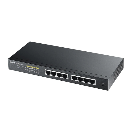
The following figures show the front panels of the Switch. Front Panel: GS1900-8 Fig ure 11 Front Panel: GS1900-8HP Fig ure 12 Revision A1 Revision B1 Front Panel: GS1900-10HP Fig ure 13 Front Panel: GS1900-16 Fig ure 14 GS1900 Series User’s Guide... -
Page 29: Ethernet Ports
An auto-negotiating port can detect and adjust to the optimum Ethernet speed (10/100/1000 Mbps) and duplex mode (full duplex or half duplex) of the connected device. An auto-crossover (auto-MDI/MDI-X) port automatically works with a straight-through or crossover Ethernet cable. GS1900 Series User’s Guide... -
Page 30: Sfp Slots
Press the transceiver firmly until it clicks into place. The Switch automatically detects the installed transceiver. Check the LEDs to verify that it is functioning properly. Remove the dust plugs from the transceiver and cables (dust plug styles vary). GS1900 Series User’s Guide... - Page 31 If unsuccessful, contact Zyxel Support to prevent damage to your Switch and transceiver. Insert the dust plug into the ports on the transceiver and the cables. GS1900 Series User’s Guide...
-
Page 32: Poe Mode (Gs1900-48Hp And Gs1900-48Hpv2 Only)
View the LEDs to ensure proper functioning of the Switch and as an aid in troubleshooting (see Section 3.3 on page 37). 3.2 Re a r Pa ne l The following figures show the rear panels of the Switch. Rear Panel: GS1900-8 Fig ure 29 GS1900 Series User’s Guide... - Page 33 Rear Panel: GS1900-16 Fig ure 32 Rear Panel: GS1900-24E Fig ure 33 Rear Panel: GS1900-24EP Fig ure 34 Rear Panel: GS1900-24 Fig ure 35 Rear Panel: GS1900-24HP Fig ure 36 Rear Panel: GS1900-24HPv2 Fig ure 37 GS1900 Series User’s Guide...
-
Page 34: Grounding
Note: The specification for surge or ESD protection assumes that the Switch is properly grounded. Remove the M4 ground screw from the Switch’s rear panel. Secure a green or yellow ground cable (16 AWG or smaller) to the Switch's rear panel using the M4 ground screw. GS1900 Series User’s Guide... - Page 35 10 ohms, or according to your country’s electrical regulations. Connecting to the Building’s Main Grounding Electrode Fig ure 43 If you are uncertain that suitable grounding is available, contact the appropriate electrical inspection GS1900 Series User’s Guide...
-
Page 36: Power Connection
Disc o nne c ting the Po we r The power input connectors can be disconnected from the power source individually. Disconnect the power cord from the power outlet. Disconnect the power cord from the AC power socket. GS1900 Series User’s Guide... -
Page 37: Leds
Green The port is in PoE AT mode. That is, the Switch is following the IEEE 802.3at standard to supply power to this port. Power is not supplied to this port. GS1900 Series User’s Guide... -
Page 38: Resetting The Switch (All Models Except Gs1900-24Ep/Gs1900-24Hpv2/Gs1900-48Hpv2)
LED begins to blink. Wait for the Switch to restart (the LED will be steady green again). This takes up to 2 minutes. Note: If you want to access the Switch Web Configurator again, you may need to change GS1900 Series User’s Guide... -
Page 39: Resetting The Switch (Gs1900-24Ep/Gs1900-24Hpv2/Gs1900-48Hpv2 Only)
LED behavior. 3.5.2 Re b o o t the Switc h Press the button to reboot the Switch without turning the power off. See Section 3.3 on page 37 RESET more information about the LED behavior. GS1900 Series User’s Guide... -
Page 40: Zon Utility
Note: It is suggested that you install Npcap, the packet capture library for Windows operating systems, and remove WinPcap or any other installed packet capture tools before you install the ZON utility. Ha rdwa re Here are the minimum hardware requirements to use the ZON Utility on your PC. GS1900 Series User’s Guide... -
Page 41: Run The Zon Utility
If your device is not listed here, see the device release notes for ZON m o de l a nd firm wa re ve rsio n utility support. The release notes are in the firmware zip file on the Zyxel web site. GS1900 Series User’s Guide... - Page 42 Select a network adapter to which your supported devices are connected. Click the button for the ZON Utility to discover all supported devices in your network. Discovery Fig ure 46 The ZON Utility screen shows the devices discovered. GS1900 Series User’s Guide...
- Page 43 Change the selected device’s IP address. 2 Renew IP Address Update a DHCP-assigned dynamic IP address. 3 Reboot Device Use this icon to restart the selected devices. This may be useful when troubleshooting or upgrading new firmware. GS1900 Series User’s Guide...
- Page 44 Once the selected device is connected to and has registered in the NCC, it will go into the Nebula cloud management mode. Serial Number Enter the admin password of the discovered device to display its serial number. Hardware Version This field displays the hardware version of the discovered device. GS1900 Series User’s Guide...
-
Page 45: Web Configurator
The Login Screen Fig ure 49 Enter the user name (default: “admin”) and password (default: “1234”). Click . If you logged in using the default user name and password, getting start appears. The L o g in GS1900 Series User’s Guide... - Page 46 1 to 20, and the allowed content is ASCII characters from 33 to 126. Access Right Select the access mode for this entry. The possible values are Re a d- O nly Re a d- Write GS1900 Series User’s Guide...
-
Page 47: Navigating The Web Configurator
Sa ve save your changes to the non-volatile memory when you are done configuring. Status Click this to display basic information about the Switch. GS1900 Series User’s Guide... -
Page 48: Navigation Panel
Switch’s navigation panel menus and their screens. Navigation Panel Fig ure 54 G e tting Sta rt Getting Start displays general device information, system status, system resource usage, and interface status. For details on Getting Start features, see Chapter 6 on page GS1900 Series User’s Guide... - Page 49 This link takes you to screen where you can view various multicast features, IGMP snooping and create multicast VLANs. IGMP VLAN Displays VLAN settings. Statistics Displays statistics settings. Group Displays group settings. Router Displays router settings. GS1900 Series User’s Guide...
- Page 50 This link takes you to a screen where you can configure the global settings for the Switch to supply power over Ethernet (PoE). Port This link takes you to a screen where you can configure port PoE settings. GS1900 Series User’s Guide...
- Page 51 This link takes you to screen where you can configure various multicast features, IGMP snooping and create multicast VLANs. IGMP Global Configure global settings. VLAN Configure VLAN settings. Router Port Configure router port settings. Profile Configure profile settings. Throttling Configure throttling settings. GS1900 Series User’s Guide...
- Page 52 User Service) or TACACS+ (Terminal Access Controller Access-Control System Plus). Auth Method Configure auth method settings. RADIUS Configure RADIUS settings. TACACS+ Configure TACACS+ settings. Management Configure syslog, SNMP, error disable, HTTP/HTTPS, users and remote access control. GS1900 Series User’s Guide...
- Page 53 This link takes you to screens where you can view system logs and can test ports. Port Test Manage cable diagnosis and test results. PING IPv4 Manage ping test settings. IPv6 Manage IPv6 ping test settings. Trace Manage trace route settings. Reboot Reset the system. GS1900 Series User’s Guide...
-
Page 54: Getting Start
Use the drop-box to select: None, 5 seconds, 10 seconds, 15 seconds, 20 seconds, 25 seconds, or 30 seconds. Virtual Device Displays an image of the Switch. Wizard Displays the following links: Start up, VLAN, QoS, and Link aggregation. GS1900 Series User’s Guide... -
Page 55: Wizard
> G e tting Sta rt Sta rt up 1 Ste p 1 Se t up IP to access this screen. Getting Start > Start up > 1 Step 1 Set up IP Fig ure 56 GS1900 Series User’s Guide... - Page 56 1234 Previous Click to show the previous screen. Pre vio us Next Click to show the next screen. Ne xt After clicking the finish screen appears. Ne xt, GS1900 Series User’s Guide...
- Page 57 In VLAN, you can create VLAN, tag VLAN setting, and view finished results. In order to create VLAN, please do the following. Click > > G e tting Sta rt VL AN 1 Ste p 1 C re a te VL AN access this screen. GS1900 Series User’s Guide...
- Page 58 Select from the drop-box a VLAN ID. Next Click to show the next screen. Ne xt After clicking Next, the tag VLAN setting screen appears. Getting Start > VLAN > 2 Step 2 Tag VLAN Setting Fig ure 60 GS1900 Series User’s Guide...
- Page 59 In order to create QoS settings, please do the following. Click > > G e tting Sta rt Q o S 1 Ste p 1 Q o S (Q ua lity to access this screen. o f Se rvic e ) GS1900 Series User’s Guide...
- Page 60 Click and drag icons located on the left to desired preference. Next Click to show the next screen. Ne xt After clicking the finish screen appears. Ne xt, Getting Start > QoS > 2 Step 2 Finish Fig ure 63 GS1900 Series User’s Guide...
- Page 61 Click and drag icons located on the left to desired preference. Group 7 Click and drag icons located on the left to desired preference. Group 8 Click and drag icons located on the left to desired preference. Next Click to show the next screen. Ne xt GS1900 Series User’s Guide...
- Page 62 Group 6 Displays summary results. Group 7 Displays summary results. Group 8 Displays summary results. Previous Click to show the previous screen. Pre vio us Finish Review the information and click to create the task. Finish GS1900 Series User’s Guide...
-
Page 63: T E C Hnic A L Re Fe Re Nc E
A RT T e c hnic a l Re fe re nc e... -
Page 64: Monitor: System
DESC RIPT IO N DHCP State This field displays the state of Dynamic Host Configuration Protocol RFC 2131 and RFC 2132 (DHCP). IP Address This field displays IP address of the Switch in the IP domain. GS1900 Series User’s Guide... -
Page 65: Ipv6
Mo nito r Syste m Info rm a tio n Syste m Info rm a tio n as shown. You can view system information. Monitor > System > Information > System Information Fig ure 68 GS1900 Series User’s Guide... - Page 66 This field displays the descriptive name of the Switch for identification purposes. System Location This field displays the geographic location of the Switch for identification purposes. System Contact This field displays the person in charge of the Switch for identification purposes. GS1900 Series User’s Guide...
-
Page 67: Monitor: Port
Use this screen to view the Switch’s port statistics. Click > > > to access this screen. Mo nito r Po rt Po rt Sta tus Monitor > Port > Port > Status Fig ure 69 GS1900 Series User’s Guide... -
Page 68: Port Counters
Use this screen to view the Switch’s port counters settings. Click > > > Mo nito r Po rt Po rt Po rt C o unte rs access this screen. Monitor > Port > Port > Port Counters (Port 1 Interface mib Counters) Fig ure 70 GS1900 Series User’s Guide... - Page 69 This field displays the ifOutOctets. ifOutUcastPkts This field displays the ifOutUcastPkts. ifOutNUcastPkts This field displays the ifOutNUcastPkts. ifOutDiscards This field displays the ifOutDiscards. ifInMulticastPkts This field displays the ifInMulticastPkts. ifInBroadcastPkts This field displays the ifInBroadcastPkts. GS1900 Series User’s Guide...
-
Page 70: Bandwidth Utilization
(Rx) traffic during the last time interval in seconds. Use this screen to view the Switch’s bandwidth utilization settings. Click > > > Mo nito r Po rt Po rt Ba ndwidth to access this screen. Utiliza tio n GS1900 Series User’s Guide... -
Page 71: Poe
The Switch supports both the IEEE 802.3af Power over Ethernet (PoE) and IEEE 802.3at High Power over Ethernet (PoE) standards. The Switch is Power Sourcing Equipment (PSE) because it provides a source of power through its Ethernet ports, and each device that receives power through an Ethernet port is a GS1900 Series User’s Guide... - Page 72 This field displays the amount of power the Switch can still provide for PoE. Note: The Switch must have at least 16 W of remaining power in order to supply power to a PoE device, even if the PoE device needs less than 16 W. GS1900 Series User’s Guide...
-
Page 73: Bandwidth Management
This field specifies the current egress burst size in bytes all ports. Burst Port Rate View the maximum bandwidth allowed in kilobits per second (Kbps) for the traffic flow on a port. Port This field displays the port number. GS1900 Series User’s Guide... -
Page 74: Storm Control
You can specify limits for each packet type on each port. Click > > to access this screen. Mo nito r Po rt Sto rm C o ntro l Monitor > Port > Storm Control Fig ure 77 GS1900 Series User’s Guide... - Page 75 Displays how many unknown unicast packets the port receives (in pps). (pps) Action Displays the action the device takes when a limit is reached. The following options are available: • – drop the packet. Dro p • – shutdown the connection. Shutdo wn GS1900 Series User’s Guide...
-
Page 76: Monitor: Vlan
Use this screen to view the Switch’s VLAN settings. Click > > > to access this Mo nito r VL AN VL AN VL AN screen. Monitor > VLAN > VLAN > VLAN Fig ure 78 GS1900 Series User’s Guide... -
Page 77: Port
This is the port VLAN identification number. A PVID (Port VLAN ID) is a tag that adds to incoming untagged frames received on a port so that the frames are forwarded to the VLAN group that the tag defines. GS1900 Series User’s Guide... -
Page 78: Vlan Port
Use this screen to view the Switch’s VLAN port settings. Click > > > Mo nito r VL AN VL AN VL AN Po rt access this screen. Monitor > VLAN > VLAN > VLAN Port Fig ure 80 GS1900 Series User’s Guide... -
Page 79: Guest Vlan
Guest VLAN Example Fig ure 81 Use this screen to view the Switch’s guest VLAN. Click > > to access this Mo nito r VL AN G ue st VL AN screen. GS1900 Series User’s Guide... -
Page 80: Voice Vlan
Use this screen to view Switch global and port voice VLAN settings for voice traffic. Click > Mo nito r VL AN > to access this screen. Vo ic e VL AN GS1900 Series User’s Guide... - Page 81 This field displays the state of the cos/802.1p. Aging Time (30-65536 min) Displays the time interval (from 30 to 65536) in minutes. Port Port This field displays a port number. State This field displays the state of a port. GS1900 Series User’s Guide...
-
Page 82: Monitor: Mac Table
Fig ure 84 This link takes you to a screen where you can view the MAC address and VLAN ID of a device attach to a port. You can also view what kind of MAC address it is. GS1900 Series User’s Guide... -
Page 83: What You Can Do In This Chapter
C le a r MAC Address This is the MAC address of the device from which this incoming frame came. VLAN Displays a type for the VLAN for identification purposes. GS1900 Series User’s Guide... - Page 84 Sta tic MAC Fo rwa rding Port This is the port from which the above MAC address was learned. Total Entries Displays the number of total entries. GS1900 Series User’s Guide...
-
Page 85: Monitor: Link Aggregation
Switch link aggregation status. Click > L ink Ag g re g a tio n Mo nito r L ink to access this screen. Ag g re g a tio n Monitor > Link Aggregation Fig ure 86 GS1900 Series User’s Guide... - Page 86 When no any physical port is binding with this group, it displays No tPre se nt Active Member Displays if this member is an active member of a trunk. Standby Member Displays if this member is an standby member of a trunk. GS1900 Series User’s Guide...
-
Page 87: Monitor: Loop Guard
. Since switch is in loop state, the probe packet returns to port . The Switch then shuts down port to ensure that the rest of the network is not affected by the switch in loop state. GS1900 Series User’s Guide... -
Page 88: What You Can Do In This Chapter
12.2 L o o p G ua rd Use the screen to view Switch loop guard status. Click > to access this L o o p G ua rd Mo nito r L o o p G ua rd screen. GS1900 Series User’s Guide... - Page 89 DESC RIPT IO N Loop Guard Port This field displays a port number. Status This field displays the status. Time Left (sec) This field displays the amount of time left in seconds. Action This field displays the action. GS1900 Series User’s Guide...
-
Page 90: Monitor: Multicast
Each field is described in the following table. Table 40 Monitor > Multicast > IGMP > VLAN L ABEL DESC RIPT IO N IGMP Vlan VLAN ID Displays the identification for the VLAN. Operate Status Displays the status of the operation. GS1900 Series User’s Guide... -
Page 91: Statistics
Each field is described in the following table. Table 41 Monitor > Multicast > IGMP > Statistics L ABEL DESC RIPT IO N IGMP Statistics Port This field displays a port number. Total RX This field displays the total amount of RX. GS1900 Series User’s Guide... -
Page 92: Group
Use this screen to view the Switch’s IGMP group. Click > > > to access this Mo nito r Multic a st IG MP G ro up screen. Monitor > Multicast > IGMP > Group Fig ure 94 GS1900 Series User’s Guide... -
Page 93: Router
This field displays the dynamic router ports. Static Router Ports This field displays the static router ports. Forbidden Router Ports This field displays the forbidden router ports. Total Entries This field displays the number of total entries. GS1900 Series User’s Guide... -
Page 94: Monitor: Spanning Tree
Monitor > Spanning Tree > CIST Fig ure 96 Each field is described in the following table. Table 44 Monitor > Spanning Tree > CIST L ABEL DESC RIPT IO N CIST Instance State This field displays the state. GS1900 Series User’s Guide... -
Page 95: Cist Port
Path cost is the cost of transmitting a frame on to a LAN through that port. It is recommended Operation to assign this value according to the speed of the bridge. The slower the media, the higher the cost. GS1900 Series User’s Guide... -
Page 96: Mst
Internal Root Cost This field displays the internal root cost. Designated Bridge For each LAN segment, a designated bridge is selected. This bridge has the lowest cost to the root among the bridges connected to the LAN. GS1900 Series User’s Guide... -
Page 97: Mst Port
The slower the media, the higher the cost. Regional Root Bridge Root bridge refers to the base of the spanning tree. Internal Root Cost This field displays the internal root cost. GS1900 Series User’s Guide... -
Page 98: Stp Statistics
Use this screen to view the Switch’s spanning tree STP statistics. Click > > Mo nito r Spa nning T re e ST P to access this screen. Sta tistic s Monitor > Spanning Tree > STP Statistics Fig ure 100 GS1900 Series User’s Guide... - Page 99 This field displays the Multiple Spanning Tree Protocol (MSTP) BDPUs received. Received Configuration BDPUs This field displays the configuration BDPUs transmitted. Transmitted TCN BDPUs This field displays the TCN BDPUs transmitted. Transmitted MSTP BDPUs This field displays the Multiple Spanning Tree Protocol (MSTP) BDPUs transmitted. Transmitted GS1900 Series User’s Guide...
-
Page 100: Monitor: Lldp
15.2.1 Sta tistic s Use this screen to view the Switch’s LLDP global and port statistics. Click > > Mo nito r L L DP Sta tistic s access this screen. GS1900 Series User’s Guide... -
Page 101: Remote Information
15.2.2 Re m o te Info rm a tio n Use this screen to view the Switch’s LLDP remote device information. Click > > Mo nito r L L DP Re m o te to access this screen. Info rm a tio n GS1900 Series User’s Guide... -
Page 102: Overloading
Use this screen to view the Switch’s LLDP port overloading. Click > > to access Mo nito r L L DP O ve rlo a ding this screen. Monitor > LLDP > Overloading Fig ure 103 GS1900 Series User’s Guide... - Page 103 Optional TLVs This field displays how many bytes used by optional TLVs. MED Inventory This field displays how many bytes used by MED inventory. 802.1 TLVs This field displays how many bytes used by 802.1 TLVs. GS1900 Series User’s Guide...
-
Page 104: Monitor: Security
MAC address learn action. When total MAC address entry is 8k, static MAC can not be configured. Use this screen to view Switch port security settings. Click > > to access this Mo nito r Se c urity Po rt Se c urity screen. GS1900 Series User’s Guide... -
Page 105: 105
Use this screen to view Switch 802.1x security settings. 16.3.1 Po rt Use this screen to view the Switch’s 802.1x port status. Click > > > to access Mo nito r Se c urity 802.1X Po rt this screen. GS1900 Series User’s Guide... -
Page 106: Authenticated Hosts
This label shows the port you are viewing. Session Time This label shows the session time. Authentication This label shows the authentication method. Method MAC Address This field displays the source MAC address in the binding. GS1900 Series User’s Guide... -
Page 107: Monitor: Management
Each field is described in the following table. Table 55 Monitor > Management > Syslog L ABEL DESC RIPT IO N Logging Filter Select Target Select Buffe re d Fla sh. Buffered: Login saved to temporary memory. Flash: Login saved to permanent memory. GS1900 Series User’s Guide... -
Page 108: Error Disable
This link takes you to a screen where you can view CPU protection and error disable recovery. Use this screen to view Switch global and port error disable management. Click > Mo nito r Ma na g e m e nt > to access this screen. Erro r Disa b le GS1900 Series User’s Guide... - Page 109 This field displays the supported features that allow the Switch to shut down a port or Reason discard packets on a port according to the feature requirements and what action you configure. Time Left (sec) This field displays the time left in seconds. Action This field displays the action. GS1900 Series User’s Guide...
-
Page 110: Configuration: System
Use this screen to view the IPv4 interface status and Switch’s management IPv4 addresses. Click > > > to open this screen. C o nfig ura tio n Syste m IPv4 Configuration > System > IP > IPv4 Fig ure 109 GS1900 Series User’s Guide... -
Page 111: The Ipv6 Screen
IPv6 properties or to manually Ena b le Disa b le Configuration enter the properties. IPv6 Address Enter the IPv6 address of the Switch in the IP domain. Gateway Enter the IPv6 address of the default outgoing gateway. GS1900 Series User’s Guide... -
Page 112: Time
Select the start date of the daylight saving time period from the dropdown lists. End Date Select the end date of the daylight saving time period from the dropdown lists. Apply Click to save the changes. Apply Cancel Click to discard the changes. C a nc e l GS1900 Series User’s Guide... -
Page 113: The Sntp Server Screen
Info rm a tio n Syste m Info rm a tio n screen as shown. You can set the system name, system location, and system contact. Configuration > System > Information > System Information Fig ure 113 GS1900 Series User’s Guide... - Page 114 Enter the geographic location of the Switch for identification purposes. System Contact Enter the person in charge of the Switch for identification purposes. Apply Click to save the changes. Apply Cancel Click to discard the changes. C a nc e l GS1900 Series User’s Guide...
-
Page 115: Configuration: Port
19.2.1 T he Po rt Sc re e n Use this screen to view Switch port settings and select ports for configuration. Click > > C o nfig ura tio n Po rt to open this screen. Po rt GS1900 Series User’s Guide... -
Page 116: The Port Edit Screen
19.2.2 T he Po rt Edit Sc re e n Use this screen to configure Switch port settings. Click > > > to open this C o nfig ura tio n Po rt Po rt Edit screen. GS1900 Series User’s Guide... -
Page 117: Eee
19.3.1 T he EEE Sc re e n Use this screen to view Switch port Energy-Efficient Ethernet (EEE) settings and select ports for configuration. Click > > > to open this screen. C o nfig ura tio n Po rt GS1900 Series User’s Guide... -
Page 118: The Eee Edit Screen
Use this screen to configure Switch port EEE settings. Click > > > > to open C o nfig ura tio n Po rt Edit this screen. Configuration > Port > EEE > EEE > Edit Fig ure 117 GS1900 Series User’s Guide... -
Page 119: Poe
This field is only available on GS1900-8HP (Revision B1) and GS1900-10HP only. Select to have the Switch pre-allocate power to each port based on the classification of Ena b le the PD device. Otherwise, select Disa b le GS1900 Series User’s Guide... -
Page 120: The Port Screen
Po rt Po E Edit • – The powered device (PD) connected to this port cannot get power. Disa b le • – The PD connected to this port can receive power. Ena b le GS1900 Series User’s Guide... - Page 121 This field displays the current amount of power consumed by the PD from the Switch on this port. Power (mW) Max Power (mW) This field displays the maximum amount of power the PD could use from the Switch on this port. Time Range GS1900 Series User’s Guide...
-
Page 122: The Poe Edit Screen
Switch to assign the remaining power to the port after all critical and Me dium high priority ports are served. Select to set the Switch to assign the remaining power to the port after all critical, high and L o w medium priority ports are served. GS1900 Series User’s Guide... - Page 123 Switch enables PoE to provide power on the port. If you leave this field blank, there is no schedule applied to the port. Apply Click to save the changes. Apply Cancel Click to discard the changes. C a nc e l GS1900 Series User’s Guide...
-
Page 124: Bandwidth Management
Displays the maximum bandwidth allowed in kilobits per second (Kbps) for the incoming traffic (Kbps) flow on a port. Egress Rate Limit Displays the maximum bandwidth allowed in kilobits per second (Kbps) for the outgoing traffic (Kbps) flow on a port. GS1900 Series User’s Guide... -
Page 125: The Port Rate Edit Screen
DLF packets is reached per second, the subsequent packets are discarded. Enable this feature to reduce broadcast, multicast and/or DLF packets in your network. You can specify limits for each packet type on each port. GS1900 Series User’s Guide... -
Page 126: The Port Screen
Use this screen to configure Storm Control settings for individual ports. Click > > C o nfig ura tio n Po rt Sto rm > > to open this screen. C o ntro l Sto rm C o ntro l Edit GS1900 Series User’s Guide... - Page 127 Ena b le (pps) Enter the maximum number of unicast packets the port can receive per second. Apply Click to save the changes. Apply Cancel Click to discard the changes. C a nc e l GS1900 Series User’s Guide...
-
Page 128: Configuration: Vlan
133) displays the global and port settings of the Switch. G ue st VL AN • The screen (Section 20.4 on page 135) displays the global, OUI, and port settings of the Vo ic e VL AN Switch. GS1900 Series User’s Guide... -
Page 129: Vlan
Enter the VLAN ID numbers. Use a dash to associate consecutive VLANs and a comma (no spaces) to associate non- consecutive VLANs. For example, 51–53 includes 51, 52 and 53, but 51,53 does not include 52. GS1900 Series User’s Guide... -
Page 130: The Port Screen
T a g O nly Unta g O nly Type Ingress Check If this check box is selected for a port, the Switch discards incoming frames for VLANs that do not include this port in its member set. GS1900 Series User’s Guide... -
Page 131: The Port Edit Screen
Enable VLAN Trunking on ports connected to other switches or routers (but not ports directly connected to end users) to allow frames belonging to unknown VLAN groups to pass through the Switch. Apply Click to save the changes. Apply Cancel Click to discard the changes. C a nc e l GS1900 Series User’s Guide... -
Page 132: The Vlan Port Screen
Table 77 Configuration > VLAN > VLAN > VLAN Port L ABEL DESC RIPT IO N VLAN Port VLAN ID Select the ID of the VLAN you want to configure. Port Displays the port index value. GS1900 Series User’s Guide... -
Page 133: Guest Vlan
Use this screen to configure the global Guest VLAN settings. Click > > > C o nfig ura tio n VL AN G ue st VL AN to open this screen. G lo b a l GS1900 Series User’s Guide... -
Page 134: The Port Screen
Configuration > VLAN > Guest VLAN > Port Fig ure 132 The following table describes the labels in this screen. Table 79 Configuration > VLAN > Guest VLAN > Port L ABEL DESC RIPT IO N Port Port Displays the port index number. GS1900 Series User’s Guide... -
Page 135: The Port Edit Screen
Use this screen to configure the global Voice VLAN settings. Click > > > C o nfig ura tio n VL AN Vo ic e VL AN to open this screen. G lo b a l GS1900 Series User’s Guide... -
Page 136: The Oui Screen
OUI process. Click > > > to open this C o nfig ura tio n VL AN Vo ic e VL AN O UI screen. Configuration > VLAN > Voice VLAN > OUI Fig ure 135 GS1900 Series User’s Guide... -
Page 137: The Oui Add Or Edit Screen
Use this screen to view the Voice VLAN port settings and select a port for configuration. Click > > > to open this screen. C o nfig ura tio n VL AN Vo ic e VL AN Po rt GS1900 Series User’s Guide... -
Page 138: The Port Edit Screen
> > > > C o nfig ura tio n VL AN Vo ic e VL AN Po rt Edit open this screen. Configuration > VLAN > Voice VLAN > Port > Edit Fig ure 138 GS1900 Series User’s Guide... - Page 139 : Enable Voice VLAN security mode operation. Ena b le d • : Disable Voice VLAN security mode operation. Disa b le d Apply Click to save the changes. Apply Cancel Click to discard the changes. C a nc e l GS1900 Series User’s Guide...
-
Page 140: Configuration: Mac Table
Static MAC MAC Address Displays the object MAC address from which this incoming frame came. VLAN Displays the VLAN group to which this frame belongs. Port Displays the port from which the above MAC address was learned. GS1900 Series User’s Guide... -
Page 141: The Static Mac Add Screen
Table 88 Configuration > MAC Table > Filtering MAC L ABEL DESC RIPT IO N Filtering MAC MAC Address Displays the filtering object MAC address from which this incoming frame came. VLAN Displays the VLAN group to which this frame belongs. GS1900 Series User’s Guide... -
Page 142: The Filtering Mac Add Screen
Table 90 Configuration > MAC Table > Dynamic Age L ABEL DESC RIPT IO N Dynamic MAC Age Aging Time Enter the aging time of the MAC address. The value can be between 10 and 630 seconds. GS1900 Series User’s Guide... - Page 143 Chapter 21 Configuration: MAC Table Table 90 Configuration > MAC Table > Dynamic Age (continued) L ABEL DESC RIPT IO N Apply Click to save the changes. Apply Cancel Click to discard the changes. C a nc e l GS1900 Series User’s Guide...
-
Page 144: Configuration: Link Aggregation
Use this screen to configure global Link Aggregation settings. Click > > C o nfig ura tio n L ink Ag g re g a tio n to open this screen. G lo b a l GS1900 Series User’s Guide... -
Page 145: The Lag Management Screen
Table 92 Configuration > Link Aggregation > LAG Management L ABEL DESC RIPT IO N LAG Management Displays the link aggregation group (LAG), that is, one logical link containing multiple ports. Name Displays the name of the link aggregation group. GS1900 Series User’s Guide... -
Page 146: The Lag Add Screen
DESC RIPT IO N LAG Management Select the link aggregation group (LAG). Name Enter the name of this entry. Type Select Sta tic L AC P Member Ports Select the member ports to be part of the LAG. GS1900 Series User’s Guide... -
Page 147: The Lag Port Screen
Use this screen to edit a LAG port. Click > > > to open this C o nfig ura tio n L ink Ag g re g a tio n L AG Po rt Edit screen. GS1900 Series User’s Guide... -
Page 148: The Lacp Port Screen
> > to open C o nfig ura tio n L ink Ag g re g a tio n L AC P Po rt this screen. Configuration > Link Aggregation > LACP Port Fig ure 149 GS1900 Series User’s Guide... -
Page 149: The Lacp Port Edit Screen
Enter a value for the port priority. The number can be between 1 and 65,535. Timer Select a timer value of either 1 second or 30 seconds. Apply Click to save the changes. Apply Cancel Click to discard the changes. C a nc e l GS1900 Series User’s Guide... -
Page 150: Configuration: Loop Guard
Enter the period (in seconds) for which a port will be kept disabled in the event of a loop is detected (and the port action shuts down the port). Apply Click to save the changes. Apply Cancel Click to discard the changes. C a nc e l GS1900 Series User’s Guide... -
Page 151: The Loop Guard Port
Use this screen to configure Loop Guard settings on a port. Click > > > C o nfig ura tio n L o o p G ua rd Po rt Edit to open this screen. Configuration > Loop Guard > Port > Edit Fig ure 153 GS1900 Series User’s Guide... - Page 152 Select to have the Switch shut down a port and/or generate a log message if it detects that packets sent out on that port loop back to the Switch. Apply Click to save the changes. Apply Cancel Click to discard the changes. C a nc e l GS1900 Series User’s Guide...
-
Page 153: Configuration: Mirror
The Switch supports local port mirroring. 24.2.1 T he Mirro r Sc re e n Use this screen to configure Mirroring. Click > to open this screen. C o nfig ura tio n Mirro r GS1900 Series User’s Guide... - Page 154 < Click to move a severity type to the acting box from the available box. > > Click to move a severity type to the acting box from the available box. > GS1900 Series User’s Guide...
- Page 155 DESC RIPT IO N < Click to move a severity type from the acting box to the available box. < Apply Click to save the changes. Apply Cancel Click to discard the changes. C a nc e l GS1900 Series User’s Guide...
-
Page 156: Configuration: Time Range Group
DESC RIPT IO N Index This field displays the index number of the rule. Name This field displays the descriptive name for this rule. This is for identification purpose only. Type This field displays the type of the rule. GS1900 Series User’s Guide... -
Page 157: The Time Range Add Screen
You need to select each day of the week the recurring schedule is effective. You also need to specify the hour and minute when the schedule begins and ends each day. The schedule begins and ends in the same day. GS1900 Series User’s Guide... -
Page 158: The Time Range Edit Screen
Ac tio n showing the name, type, and range of this rule. Click the button again to modify it, or you can click Edit button to create a new range under a periodic time range rule. GS1900 Series User’s Guide... - Page 159 You need to select each day of the week the recurring schedule is effective. You also need to specify the hour and minute when the schedule begins and ends each day. The schedule begins and ends in the same day. GS1900 Series User’s Guide...
- Page 160 Sa ve your changes to the non-volatile memory when you are done configuring. Cancel Click to reset the fields to your previous configuration. C a nc e l GS1900 Series User’s Guide...
-
Page 161: Configuration: Multicast
L ABEL DESC RIPT IO N Global Snooping State Select to turn on IGMP packet snooping or to turn snooping off. Ena b le Disa b le Snooping Select depending on the snooping version you require. Version GS1900 Series User’s Guide... -
Page 162: The Vlan Screen
State Displays the Switch current VLAN querier entry as Ena b le Disa b le Version Displays the Switch current VLAN querier entry version. Edit Click to change the properties of the IGMP VLAN entry. Edit GS1900 Series User’s Guide... -
Page 163: The Edit Igmp Screen
Ena b le Disa b le State IGMP Querier Select the IGMP Querier version to Version Apply Click to save the changes. Apply Cancel Click to discard the changes. C a nc e l GS1900 Series User’s Guide... -
Page 164: The Router Port Screen
Use this screen to configure the settings. Click > > > Ro ute r Po rt C o nfig ura tio n Multic a st IG MP Ro ute r Po rt > to open this screen. Edit GS1900 Series User’s Guide... -
Page 165: The Profile Screen
Click > > > to open IG MP Pro file C o nfig ura tio n Multic a st IG MP Pro file this screen. Configuration > Multicast > IGMP > Profile Fig ure 165 GS1900 Series User’s Guide... -
Page 166: The Add Or Edit Profile Screen
26.2.8 T he T hro ttling Sc re e n Use this screen to view the settings. Click > > > to open T hro ttling C o nfig ura tio n Multic a st IG MP T hro ttling this screen. GS1900 Series User’s Guide... -
Page 167: The Edit Throttling Screen
26.2.9 T he Edit T hro ttling Sc re e n Use this screen to configure the settings. Click > > > > T hro ttling C o nfig ura tio n Multic a st IG MP T hro ttling to open this screen. Edit GS1900 Series User’s Guide... - Page 168 Re pla c e Number Action Filter Profile ID Select the throttling filter profile ID from the dropdown list. Apply Click to save the changes. Apply Cancel Click to discard the changes. C a nc e l GS1900 Series User’s Guide...
-
Page 169: Configuration: Spanning Tree
> > to open this G lo b a l C o nfig ura tio n Spa nning T re e G lo b a l screen. Configuration > Spanning Tree > Global Fig ure 169 GS1900 Series User’s Guide... -
Page 170: The Stp Port Screen
Click > > to open this ST P Po rt C o nfig ura tio n Spa nning T re e ST P Po rt screen. Configuration > Spanning Tree > STP Port Fig ure 170 GS1900 Series User’s Guide... -
Page 171: The Stp Port Edit Screen
Note: An edge port becomes a non-edge port as soon as it receives a Bridge Protocol Data Unit (BPDU). BPDU Filter Select to activate BPDU filter or to deactivate it. Ye s GS1900 Series User’s Guide... -
Page 172: The Cist Screen
This is the time interval in seconds between BPDU (Bridge Protocol Data Units) configuration message generations by the root switch. The allowed range is 1 to 10 seconds. Apply Click to save the changes. Apply Cancel Click to discard the changes. C a nc e l GS1900 Series User’s Guide... -
Page 173: The Cist Port Screen
Use this screen to configure the settings. Click > > > C IST Po rt Edit C o nfig ura tio n Spa nning T re e C IST Po rt to open this screen. Edit GS1900 Series User’s Guide... -
Page 174: The Mst Screen
This displays the priority for each port here. Action Edit Click to make changes to the entry. Edit Delete Click to remove the entry. De le te Click to create a new entry. MST Insta nc e GS1900 Series User’s Guide... -
Page 175: The Add Or Edit Mst Screen
27.2.9 T he MST Po rt Sc re e n Use this screen to view the settings. Click > > to open this MST Po rt C o nfig ura tio n Spa nning T re e MST Po rt screen. GS1900 Series User’s Guide... -
Page 176: The Mst Port Edit Screen
27.2.10 T he MST Po rt Edit Sc re e n Use this screen to configure the settings. Click > > > MST Po rt Edit C o nfig ura tio n Spa nning T re e MST Po rt to open this screen. Edit GS1900 Series User’s Guide... - Page 177 0 and 255 and the default value is 128. Internal Path Enter the internal path cost. Enter for Auto. Cost (0=Auto) Apply Click to save the changes. Apply Cancel Click to discard the changes. C a nc e l GS1900 Series User’s Guide...
-
Page 178: Configuration: Lldp
The switch periodically transmits LLDP frames to its neighbors for having the network discovery information up-to-date. The interval between each LLDP frame is determined by the Tx Interval value. Valid values are restricted to 5 – 32768 seconds. GS1900 Series User’s Guide... -
Page 179: The Port Screen
28.2.2 T he Po rt Sc re e n Use this screen to view the settings. Click > > to open this screen. Po rt C o nfig ura tio n L L DP Po rt GS1900 Series User’s Guide... -
Page 180: The Port Edit Screen
28.2.3 T he Po rt Edit Sc re e n Use this screen to configure the settings. Click > > > to open this Po rt Edit C o nfig ura tio n L L DP Po rt Edit screen. GS1900 Series User’s Guide... -
Page 181: The Local Information Screen
Click > > L o c a l Info rm a tio n C o nfig ura tio n L L DP L o c a l Info rm a tio n open this screen. GS1900 Series User’s Guide... - Page 182 LLDP frames. C ha ssis ID System Name is the name advertised by the neighbor unit. Syste m Na m e System Displays the Syste m De sc riptio n Description GS1900 Series User’s Guide...
-
Page 183: The Local Information Edit Screen
Use this screen to configure the settings. Click > > > Po rt Edit C o nfig ura tio n L L DP L o c a l Info rm a tio n Edit open this screen. GS1900 Series User’s Guide... - Page 184 SHOULD be normalized to within 0 – 90 degrees with a maximum of 4 digits. L a titude It is possible to specify the direction to either of the equator or of the equator. No rth So uth GS1900 Series User’s Guide...
- Page 185 Emergency Call Service ELIN identifier data format is defined to carry the ELIN identifier as used during emergency call setup to a traditional CAMA or ISDN trunk-based PSAP. This format consists of a numerical digit string, corresponding to the ELIN to be used for emergency calling. GS1900 Series User’s Guide...
-
Page 186: The Med Network Policy Screen
Po rt Edit C o nfig ura tio n L L DP MED Ne two rk Po lic y to open this screen. Edit Configuration > LLDP > MED Network Policy > Add or Edit Fig ure 185 GS1900 Series User’s Guide... -
Page 187: The Med Port Screen
28.2.8 T he MED Po rt Sc re e n Use this screen to view the settings. Click > > to open this screen. MED Po rt C o nfig ura tio n L L DP MED Po rt GS1900 Series User’s Guide... -
Page 188: The Med Port Edit Screen
28.2.9 T he MED Po rt Edit Sc re e n Use this screen to configure the settings. Click > > > MED Po rt Edit C o nfig ura tio n L L DP MED Po rt Edit open this screen. GS1900 Series User’s Guide... - Page 189 MED Ne two rk Po lic ie s Ava ila b le Ac ting Policy activate. Apply Click to save the changes. Apply Cancel Click to discard the changes. C a nc e l GS1900 Series User’s Guide...
-
Page 190: Configuration: Qos
29.2.1 T he Po rt Sc re e n Use this screen to view the settings. Click > > > to open this screen. Po rt C o nfig ura tio n Q o S G e ne ra l Po rt GS1900 Series User’s Guide... -
Page 191: The Port Edit Screen
29.2.2 T he Po rt Edit Sc re e n Use this screen to configure the settings. Click > > > > Po rt Edit C o nfig ura tio n Q o S G e ne ra l Po rt Edit open this screen. GS1900 Series User’s Guide... -
Page 192: The Queue Screen
> > to open this Q ue ue C o nfig ura tio n Q o S G e ne ra l Q ue ue screen. Configuration > QoS > General > Queue Fig ure 190 GS1900 Series User’s Guide... -
Page 193: The Cos Mapping Screen
The following table describes the labels in this screen. Table 138 Configuration > QoS > General > CoS Mapping L ABEL DESC RIPT IO N CoS to Queue Mapping Class of Service (CoS) Displays a listing of the CoS, range: 0 – 7. GS1900 Series User’s Guide... -
Page 194: The Dscp Mapping Screen
DSC P Ma pping C o nfig ura tio n Q o S G e ne ra l DSC P to open this screen. Ma pping Configuration > QoS > General > DSCP Mapping Fig ure 192 GS1900 Series User’s Guide... -
Page 195: The Ip Precedence Mapping Screen
Fig ure 193 The following table describes the labels in this screen. Table 140 Configuration > QoS > General > IP Precedence Mapping L ABEL DESC RIPT IO N IP Precedence Mapping IP Precedence to Queue Mapping GS1900 Series User’s Guide... -
Page 196: Trust Mode
29.3.2 T he Po rt Sc re e n Use this screen to view the settings. Click > > > to open this Po rt C o nfig ura tio n Q o S T rust Mo de Po rt screen. GS1900 Series User’s Guide... -
Page 197: The Trust Mode Edit Screen
Use this screen to configure the settings. Click > > > > T rust Mo de C o nfig ura tio n Q o S T rust Mo de Po rt Edit to open this screen. GS1900 Series User’s Guide... - Page 198 Displays the port index values. Mode Select the for the QoS port list as T rust Mo de T rust Untrust Apply Click to save the changes. Apply Cancel Click to discard the changes. C a nc e l GS1900 Series User’s Guide...
-
Page 199: Configuration: Security
30.2.2 T he Po rt Sc re e n Use this screen to view the settings. Click > > > to open this Po rt C o nfig ura tio n Se c urity Po rt Se c urity Po rt screen. GS1900 Series User’s Guide... -
Page 200: The Port Edit Screen
Select the ports you want to configure and then click Po rt Edit > > > screen to open this screen. C o nfig ura tio n Se c urity Po rt Se c urity Po rt GS1900 Series User’s Guide... -
Page 201: Protected Port
30.3.1 T he Pro te c te d Po rt Sc re e n Use this screen to view the settings. Click > > to open this Po rt C o nfig ura tio n Se c urity Pro te c te d Po rt screen. GS1900 Series User’s Guide... -
Page 202: The Protected Port Edit Screen
> > > Po rt C o nfig ura tio n Se c urity Pro te c te d Po rt Edit open this screen. Configuration > Security > Protected Port > Edit Fig ure 201 GS1900 Series User’s Guide... -
Page 203: 203
30.4.2 T he Po rt Sc re e n Use this screen to view the settings. Click > > > to open this screen. Po rt C o nfig ura tio n Se c urity 802.1X Po rt GS1900 Series User’s Guide... -
Page 204: The Port Edit Screen
30.4.3 T he Po rt Edit Sc re e n Use this screen to configure the settings. Click > > > > to open Po rt C o nfig ura tio n Se c urity 802.1X Po rt Edit this screen. GS1900 Series User’s Guide... -
Page 205: Dos
Use this screen to view the settings. Click > > > to open this G lo b a l C o nfig ura tio n Se c urity Do S G lo b a l screen. GS1900 Series User’s Guide... -
Page 206: The Port Screen
The following table describes the labels in this screen. Table 153 Configuration > Security > DoS > Port L ABEL DESC RIPT IO N Port Port Displays the port index value. State Displays the port’s DoS feature as Ena b le Disa b le GS1900 Series User’s Guide... -
Page 207: The Port Edit Screen
These attacks result from sending a specially crafted packet to Attack) a machine where the source host UDP/TCP port is the same as the destination host UDP/TCP port. The system attempts to reply to itself, resulting in system lockup. GS1900 Series User’s Guide... - Page 208 TCP sequence number is zero and all control bits are zeros. XMAS (Scan Attack) Layer 3 IPv4/IPv6 TCP sequence number is zero and the FIN, URG and PSH bits are set. SYN_FIN Layer 3 IPv4/IPv6 SYN and FIN bits are set in the TCP packet. GS1900 Series User’s Guide...
-
Page 209: Configuration: Aaa
31.2.2 T he Auth Me tho d Add o r Edit Sc re e n Use this screen to configure the settings. Click > > > Auth Me tho d C o nfig ura tio n Auth Me tho d to open this screen. Edit GS1900 Series User’s Guide... -
Page 210: Radius
Displays the authentication key. Time out Displays the number of time outs for replies. The value can be between 1 and 30 seconds. Retries Displays the number of retries. The value can be between 1 and 30. GS1900 Series User’s Guide... -
Page 211: The Radius Add Or Edit Screen
Hig h L o w Usage Select the server usage type as , or L o g in 802.1X Apply Click to save the changes. Apply Cancel Click to discard the changes. C a nc e l GS1900 Series User’s Guide... -
Page 212: Tacacs
Use this screen to configure the settings. Click > > > T AC AC S+ C o nfig ura tio n T AC AC S+ Edit open this screen. Configuration > AAA > TACACS+ > Add or Edit Fig ure 213 GS1900 Series User’s Guide... - Page 213 Timeout for Reply Enter the number of time outs for replies. The value can be between seconds. Server Priority Select the server priority as Hig h L o w Apply Click to save the changes. Apply Cancel Click to discard the changes. C a nc e l GS1900 Series User’s Guide...
-
Page 214: Configuration: Management
Use this screen to view the settings. Click > > > to open L o c a l C o nfig ura tio n Ma na g e m e nt Syslo g L o c a l this screen. GS1900 Series User’s Guide... -
Page 215: The Local Add Or Edit Screen
Apply Click to save the changes. Apply Cancel Click to discard the changes. C a nc e l GS1900 Series User’s Guide... -
Page 216: The Remote Screen
Table 166 Configuration > Management > Syslog > Remote > Add or Edit L ABEL DESC RIPT IO N Remote Server Enter the IP address or domain name of the syslog server. Server Port Enter port number of the syslog server. GS1900 Series User’s Guide... -
Page 217: Snmp
Use this screen to view the settings. Click > > > C o m m unity C o nfig ura tio n Ma na g e m e nt SNMP to open this screen. C o m m unity GS1900 Series User’s Guide... -
Page 218: The Community Add Screen
32.3.4 T he G ro up Sc re e n Use this screen to view the settings. Click > > > to open G ro up C o nfig ura tio n Ma na g e m e nt SNMP G ro up this screen. GS1900 Series User’s Guide... -
Page 219: The Group Add Screen
DESC RIPT IO N SNMPv3 Group Group Name Enter a string identifying the group name that this entry should belong to. The allowed string length is 1 to 30, and the allowed content is ASCII characters from GS1900 Series User’s Guide... -
Page 220: The User Screen
Displays the access mode for this entry. The possible values are Re a d- O nly Re a d- Write Action Delete Click to remove the entry. De le te Click to create a new SNMP user. GS1900 Series User’s Guide... -
Page 221: The User Add Screen
32.3.8 T he T ra p Sc re e n Use this screen to configure the settings. Click > > > to open T ra p C o nfig ura tio n Ma na g e m e nt SNMP T ra p this screen. GS1900 Series User’s Guide... -
Page 222: The Trap Destination Screen
The following table describes the labels in this screen. Table 175 Configuration > Management > SNMP > Trap Destination L ABEL DESC RIPT IO N SNMP Trap Host Server Displays a string identifying the server address that this entry belongs to. GS1900 Series User’s Guide... -
Page 223: The Trap Destination Add Screen
Displays the user name that this entry belongs to. UDP Port Enter a UDP port for this entry. Apply Click to save the changes. Apply Cancel Click to discard the changes. C a nc e l GS1900 Series User’s Guide... -
Page 224: Error Disable
Use this screen to configure the settings. Click > > > HT T P C o nfig ura tio n Ma na g e m e nt HT T P/ HT T PS HT T P open this screen. GS1900 Series User’s Guide... -
Page 225: The Https Screen
Table 179 Configuration > Management > HTTP/HTTPS > HTTPS L ABEL DESC RIPT IO N HTTPS State Select the HTTPS mode operation. Possible mode is: • : Enable HTTPS mode operation. Ena b le Authentication Select the authentication method from the dropdown list. Method GS1900 Series User’s Guide... -
Page 226: Telnet/Ssh
Click > > > C o nfig ura tio n Ma na g e m e nt T e lne t/ SSH open this screen. Configuration > Management > Telnet/SSH > SSH Fig ure 233 GS1900 Series User’s Guide... -
Page 227: Users
32.7.2 T he Use rs Add o r Edit Sc re e n Use this screen to configure the settings. Click > > > Use rs C o nfig ura tio n Ma na g e m e nt Use rs Edit to open this screen. GS1900 Series User’s Guide... -
Page 228: Remote Access Control
Ma na g e m e nt Re m o te Ac c e ss > to open this screen. C o ntro l G lo b a l Configuration > Management > Remote Access Control > Global Fig ure 236 GS1900 Series User’s Guide... -
Page 229: The Profile Add Or Edit Screen
Re m o te Ac c e ss > > to open this screen. C o ntro l G lo b a l Edit Configuration > Management > Remote Access Control > Global > Add or Edit Fig ure 237 GS1900 Series User’s Guide... - Page 230 Select the service to use for remote access. The values are , or AL L HT T P HT T PS SNMP Apply Click to save the changes. Apply Cancel Click to discard the changes. C a nc e l GS1900 Series User’s Guide...
-
Page 231: Maintenance
Browse to the path on your computer to upload the firmware you want as the active image. 33.1.2 Upg ra de the firm wa re fro m a file o n a se rve r Follow the steps below to upgrade the firmware from a TFTP server. GS1900 Series User’s Guide... -
Page 232: Upgrade The Firmware From A File On Your Computer
From the screen, display the screen as shown next. Use this screen Ma inte na nc e Firm wa re Ma na g e m e nt to view image information and activate an image. GS1900 Series User’s Guide... -
Page 233: Select The Active Image
, choose the backup image according to the information displayed in Ac tive Im a g e Im a g e s Info r- m a tio n Click to activate the backup image. Apply Click to discard the changes. C a nc e l GS1900 Series User’s Guide... -
Page 234: Backup A Configuration File
CPU utilization, history, memory and Mbuf (Memory Buffer) log, and crash reports for issue analysis by customer support should you have difficulty with your Switch. Apply Click to save the changes. Apply Cancel Click to discard the changes. C a nc e l GS1900 Series User’s Guide... -
Page 235: Back Up Configuration Or Log Files To A Server
Web Configurator for restoring the configuration file. Alternatively, HT T P choose to download the snapshot from a TFTP server. T FT P Server IP To download from a TFTP server, enter the TFTP server IP address. GS1900 Series User’s Guide... -
Page 236: Restore The Configuration From A File On A Server
> to display the screen as shown next. Use this screen Ma inte na nc e C o nfig ura tio n Ma na g e m e nt to replace startup and backup configuration files. GS1900 Series User’s Guide... -
Page 237: Reset To Factory Defaults
Note: If you want to access the Switch Web Configurator again, you may need to change the IP address of your computer to be in the same subnet as that of the default Switch IP address (192.168.1.1). GS1900 Series User’s Guide... -
Page 238: Network Diagnostics
33.7.2 IPv4 Ping T e st Click > > > in the navigation panel to open this screen. Use this Ma inte na nc e Dia g no stic s PING IPv4 screen to ping an IPv4 server. GS1900 Series User’s Guide... - Page 239 Inte rva l , enter the packet size in bytes Size Click to perform the ping test. Apply Click to discard the changes. C a nc e l The test results are displayed in Re sults GS1900 Series User’s Guide...
-
Page 240: Ipv6 Ping Test
IPv6 Addre ss , enter the number of ping packets. C o unt , enter the time interval in seconds. Inte rva l , enter the packet size in bytes. Size Click to perform the ping test. Apply GS1900 Series User’s Guide... -
Page 241: Trace Route
, enter the IPv6 address. IP Addre ss , enter the number of hops. Ho ps Click to perform the test. Apply Click to discard the changes. C a nc e l The test results are displayed in Re sult GS1900 Series User’s Guide... -
Page 242: Reboot
Re b o o t Click and then wait for the Switch to restart. This process takes up to 2 minutes and does not affect the Switch’s configuration. Click to discard the changes. C a nc e l GS1900 Series User’s Guide... -
Page 243: Troubleshooting
Turn the Switch off and on (in DC models or if the DC power supply is connected in AC/DC models). Disconnect and re-connect the power adapter or cord to the Switch (in AC models or if the AC power GS1900 Series User’s Guide... -
Page 244: Switch Access And Login
Switch, skip this step.) Reset the device to its factory defaults, and try to access the Switch with the default IP address. See Section 3.4 on page 38 Section 33.6 on page 237. GS1900 Series User’s Guide... -
Page 245: Switch Configuration
Click Sa ve the top right corner of the Web Configurator to save the configuration permanently. See also Section 5.3.1 on page 47 for more information about how to save your configuration. GS1900 Series User’s Guide... -
Page 246: Appendix A Customer Support
C o rpo ra te He a dq ua rte rs (Wo rldwide ) T a iwa n • Zyxel Communications Corporation • http://www.zyxel.com Asia C hina • Zyxel Communications (Shanghai) Corp. Zyxel Communications (Beijing) Corp. Zyxel Communications (Tianjin) Corp. • https://www.zyxel.com/cn/zh/ India • Zyxel Technology India Pvt Ltd. - Page 247 • Zyxel Communications Corporation • https://www.zyxel.com/tw/zh/ T ha ila nd • Zyxel Thailand Co., Ltd. • https://www.zyxel.com/th/th/ Vie tna m • Zyxel Communications Corporation-Vietnam Office • https://www.zyxel.com/vn/vi Euro pe Be la rus • Zyxel BY • https://www.zyxel.by Be lg ium •...
- Page 248 Appendix A Customer Support • https://www.zyxel.com/be/fr/ Bulg a ria • Zyxel България • https://www.zyxel.com/bg/bg/ C ze c h Re pub lic • Zyxel Communications Czech s.r.o • https://www.zyxel.com/cz/cs/ De nm a rk • Zyxel Communications A/S • https://www.zyxel.com/dk/da/ Esto nia •...
- Page 249 Ro m a nia • Zyxel Romania • https://www.zyxel.com/ro/ro Russia • Zyxel Russia • https://www.zyxel.com/ru/ru/ Slo va kia • Zyxel Communications Czech s.r.o. organizacna zlozka • https://www.zyxel.com/sk/sk/ Spa in • Zyxel Communications ES Ltd. • https://www.zyxel.com/es/es/ Swe de n • Zyxel Communications •...
- Page 250 Appendix A Customer Support T urke y • Zyxel Turkey A.S. • https://www.zyxel.com/tr/tr/ • Zyxel Communications UK Ltd. • https://www.zyxel.com/uk/en/ Ukra ine • Zyxel Ukraine • http://www.ua.zyxel.com So uth Am e ric a Arg e ntina • Zyxel Communications Corporation •...
- Page 251 Appendix A Customer Support Middle Ea st • Zyxel Communications Corporation • https://www.zyxel.com/me/en/ No rth Am e ric a • Zyxel Communications, Inc. – North America Headquarters • https://www.zyxel.com/us/en/ O c e a nia Austra lia • Zyxel Communications Corporation •...
-
Page 252: Appendix B Legal Information
The contents of this publication may not be reproduced in any part or as a whole, transcribed, stored in a retrieval system, translated into any language, or transmitted in any form or by any means, electronic, mechanical, magnetic, optical, chemical, photocopying, manual, or otherwise, without the prior written permission of Zyxel Communications Corporation. Published by Zyxel Communications Corporation. All rights reserved. - Page 253 APPAREIL À LASER DE CLASS 1 (for products with mini-GBIC slots or laser products, such as fiber-optic transceiver and GPON products). • PRODUIT CONFORME SELON 21 CFR 1040.10 ET 1040.11. (for products with mini-GBIC slots or laser products, such as fiber-optic transceiver and GPON products) GS1900 Series User’s Guide...
- Page 254 • 若接上不正確的電源變壓器會有爆炸的風險。。 • 請勿隨意更換產品內的電池。 • 如果更換不正確之電池型式,會有爆炸的風險,請依製造商說明書處理使用過之電池。 • 請將廢電池丟棄在適當的電器或電子設備回收處。 • 請勿將設備解體。 • 請勿阻礙設備的散熱孔,空氣對流不足將會造成設備損害。 • 請插在正確的電壓供給插座 ( 如 : 北美 / 台灣電壓 110V AC,歐洲是 230V AC)。 • 假若電源變壓器或電源變壓器的纜線損壞,請從插座拔除,若您還繼續插電使用,會有觸電死亡的風險。 • 請勿試圖修理電源變壓器或電源變壓器的纜線,若有毀損,請直接聯絡您購買的店家,購買⼀個新的電源變壓器。 • 請勿將此設備安裝於室外,此設備僅適合放置於室內。 • 請勿隨⼀般垃圾丟棄。 • 請參閱產品背貼上的設備額定功率。 • 請參考產品型錄或是彩盒上的作業溫度。 GS1900 Series User’s Guide...
- Page 255 The following information applies if you use the product within Canada area Industry C a na da IC ES sta te m e nt CAN ICES-3 (B)/NMB-3(B) EURO PEA N UNIO N The following information applies if you use the product within the European Union. GS1900 Series User’s Guide...
- Page 256 125/EC establishing a framework for the setting of ecodesign requirements for energy-related products (recast), so called as "ErP Directive (Energy-related Products directive) as well as ecodesign requirement laid down in applicable implementing measures, power consumption has satisfied regulation requirements which are: • Network standby power consumption < 8W, and/or GS1900 Series User’s Guide...
- Page 257 Various symbols are used in this product to ensure correct usage, to prevent danger to the user and others, and to prevent property damage. The meaning of these symbols are described below. It is important that you read these descriptions thoroughly and fully understand the contents. GS1900 Series User’s Guide...
- Page 258 T ra de m a rks ZyNOS (Zyxel Network Operating System) and ZON (Zyxel One Network) are registered trademarks of Zyxel Communications, Inc. Other trademarks mentioned in this publication are used for identification purposes only and may be properties of their respective owners.
-
Page 259: Inde X
EIA standard size bandwidth contention electrical inspection authority alleviate electrical regulation electrician electrostatic discharge (ESD) ESD preventive wrist strap ESD protection certifications viewing Ethernet port default setting clearance Switch installation comparison table Switch GS1900 Series User’s Guide... - Page 260 LED descriptions LEDs Link/ACT LED Login screen logout half duplex 47, 48 Web Configurator hardware installation loop guard hardware overview how it works 87, 88 HTML5 support probe packet HTTP GS1900 Series User’s Guide...
- Page 261 Neighbor Discovery Protocol Rapid Spanning Tree Protocol, see RSTP network applications rear panel network bottleneck recurring schedule eliminate remote management Npcap using PING 38, 39 RESET button reset the Switch resetting RESTORE button one-time schedule restoring configuration GS1900 Series User’s Guide...
- Page 262 55, 64, 65, 111, 140, 141, 142 WinPcap system name wiring closet system uptime 21, 40 ZON utility telnet hardware requirements TFTP installation requirements GS1900 Series User’s Guide...
- Page 263 Index supported devices supported firmware version Zyxel Discovery Protocol (ZDP) Zyxel One Network (ZON) GS1900 Series User’s Guide...
Need help?
Do you have a question about the GS1900 Series and is the answer not in the manual?
Questions and answers