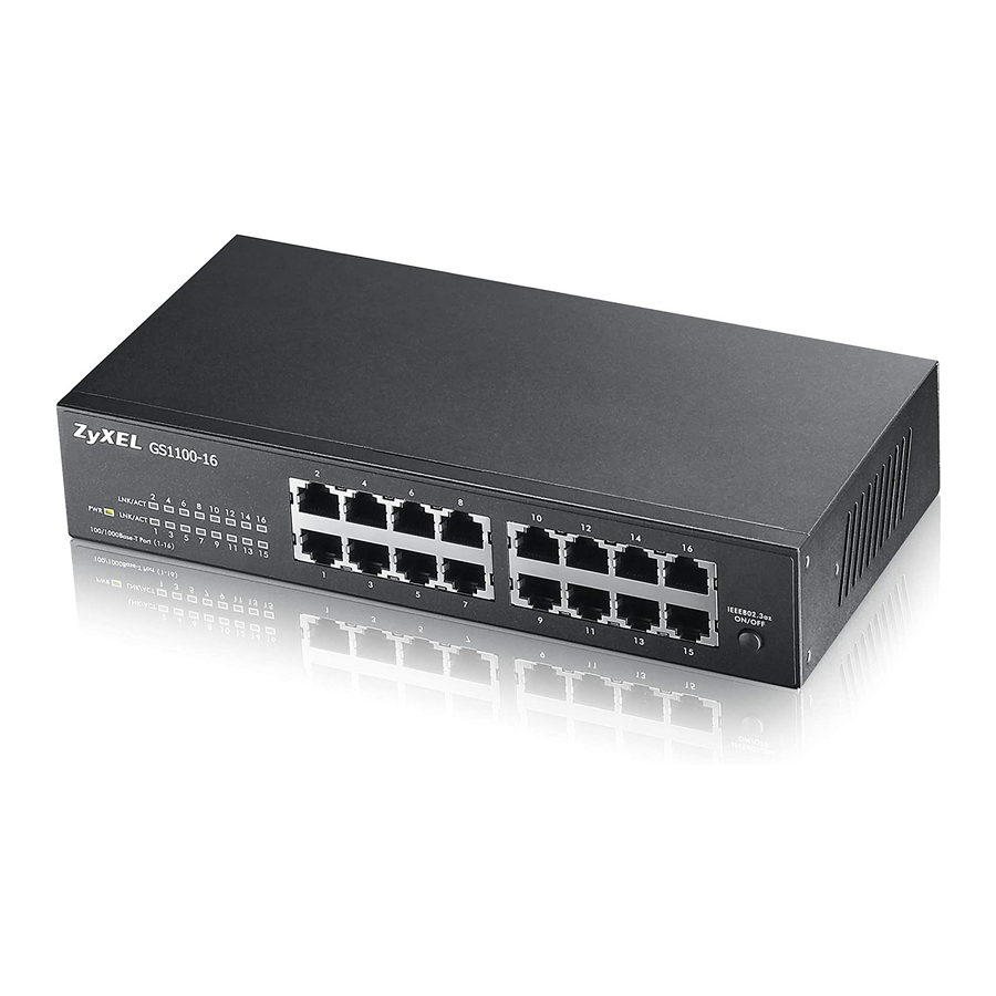
ZyXEL Communications GS1100-16 User Manual
Unmanaged gigabit ethernet switch
Hide thumbs
Also See for GS1100-16:
- User manual (30 pages) ,
- Specifications (2 pages) ,
- Quick manual (2 pages)

Related Manuals for ZyXEL Communications GS1100-16


Summary of Contents for ZyXEL Communications GS1100-16
- Page 1 GS1100 Series Unmanaged Gigabit Ethernet Switch Version 1.00 Edition 4, 02/2013 Quick Start Guide User’s Guide www.zyxel.com Copyright © 2013 ZyXEL Communications Corporation...
- Page 2 IMPORTANT! READ CAREFULLY BEFORE USE. KEEP THIS GUIDE FOR FUTURE REFERENCE. Screenshots and graphics in this book may differ slightly from your product due to differences in your product firmware or your computer operating system. Every effort has been made to ensure that the information in this manual is accurate.
-
Page 3: Table Of Contents
Table of Contents Table of Contents Table of Contents ..........................3 Chapter 1 Getting to Know Your Switch.......................5 1.1 Introduction ............................5 1.2 Features ..............................6 1.3 Applications ............................6 1.3.1 Standalone Workgroup ......................7 1.3.2 Bridging .............................7 1.4 Power Over Ethernet (PoE) ........................7 Chapter 2 Hardware Description and Connection ....................9 2.1 Rear Panel ............................9... -
Page 4: Gs1100 Series User's Guide
Table of Contents GS1100 Series User’s Guide... -
Page 5: Getting To Know Your Switch
This chapter describes the key features, benefits and applications of your Switch. This User’s Guide covers the following models: GS1100-8HP, GS1100-16, GS1100-24, and GS1100- 24E. The Switch is a 10/100/1000 Mbps multi-port switch that can be used to build high- performance switched workgroup networks. -
Page 6: Chapter 1 Getting To Know Your Switch
Chapter 1 Getting to Know Your Switch Figure 1 Front Panel GS1100-8HP GS1100-16 GS1100-24 GS1100-24E 1.2 Features The following are the essential features of the Switch. • Conforms to IEEE 802.3, 802.3u, 802.3ab and 802.3x standards. • Auto-negotiating 10/100/1000 Mbps Gigabit Ethernet (GbE) RJ-45 ports. -
Page 7: Standalone Workgroup
Chapter 1 Getting to Know Your Switch 1.3.1 Standalone Workgroup In this application, the Switch is an ideal solution for small networks where rapid growth can be expected in the near future. The Switch can be used standalone for a group of heavy traffic users. You can connect computers directly to the Switch’s port or connect other switches to the Switch. - Page 8 Chapter 1 Getting to Know Your Switch Ports 1 to 4 on the GS1100-8HP are IEEE 802.3at High Power over Ethernet (PoE) compliant and can supply power of up to 30W per Ethernet port and up to the total PoE power budget per Switch. A powered device (PD) is a device such as an access point or a switch, that supports PoE (Power over Ethernet) so that it can receive power from another device through a 10/100/1000 Mbps Ethernet port.
-
Page 9: Hardware Description And Connection
Connect one end of the supplied power cord or power adaptor to the power receptacle on the back of the Switch and the other end to the appropriate power source. For the GS1100-8HP, GS1100-16 and GS1100-24E, use the POWER ON/OFF switch to have the Switch power on or off. -
Page 10: Chapter 2 Hardware Description And Connection
Chapter 2 Hardware Description and Connection The GS1100-24 has two SFP slots. Refer to Section 2.2.3 on page 10 for more information. 2.2.1 RJ-45 Auto-negotiating Ports The 10 Base-T/100 Base-TX/1000 Base-T RJ-45 ports are auto-negotiating and auto-crossover. An auto-negotiating port can detect and adjust to the optimum Ethernet speed (10/100/1000 Mpbs) and duplex mode (full duplex or half duplex) of the connected device. - Page 11 Chapter 2 Hardware Description and Connection Press the transceiver firmly until it clicks into place. The Switch automatically detects the installed transceiver. Check the LEDs to verify that it is functioning properly. Close the transceiver’s latch (latch styles vary). Connect the fiber optic cables to the transceiver. Figure 6 Transceiver Installation Example Figure 7 Connecting the Fiber Optic Cables 2.2.3.2 Transceiver Removal...
-
Page 12: Front Panel Connections
Chapter 2 Hardware Description and Connection Figure 10 Transceiver Removal Example 2.2.4 Front Panel Connections You can use unshielded twisted pair (UTP) or shielded twisted-pair (STP) Ethernet cables for RJ-45 ports. The following table describes the types of network cable used for the different connection speeds. - Page 13 Chapter 2 Hardware Description and Connection Figure 11 Front Panel LEDs GS1100-8HP GS1100-16 GS1100-24 GS1100-24E The following table describes the LEDs. Table 3 The Front Panel LED Descriptions: GS1100-8HP COLOR STATUS DESCRIPTION Green The Switch is on and receiving power.
-
Page 14: Hardware Installation
Note: Ask an authorized technician to attach the Switch to the rack/wall. For GS1100-8HP, GS1100-16 and GS110-24E, you can place the Switch directly on top of your desk or have it wall-mounted. For GS1100-16, GS1100-24 and GS110-24E, the size is suitable for rack- mounting and you can refer to Section 2.3.2 on page 15... -
Page 15: Rack Mounting
Table 6 Distance between the centers of the holes for wall mounting MODEL DISTANCE GS1100-8HP 120 mm GS1100-16 148 mm GS1100-24E 207 mm Screw the two screws provided with your Switch into the wall (see the figure in step 2). Use screws with 6 mm ~ 8 mm (0.24"... -
Page 16: Mounting The Switch On A Rack
Position a mounting bracket on one side of the Switch, lining up the four screw holes on the bracket with the screw holes on the side of the Switch. Figure 12 Attaching the Mounting Brackets (GS1100-16 and GS1100-24E) Figure 13 Attaching the Mounting Brackets (GS1100-24) Using a #2 Philips screwdriver, install the M3 flat head screws through the mounting bracket holes into the Switch. - Page 17 Chapter 2 Hardware Description and Connection Figure 14 Mounting the Switch on a Rack (GS1100-16 and GS1100-24E) Figure 15 Mounting the Switch on a Rack (GS1100-24) Using a #2 Philips screwdriver, install the M5 flat head screws through the mounting bracket holes into the rack.
- Page 18 Chapter 2 Hardware Description and Connection GS1100 Series User’s Guide...
-
Page 19: Chapter 3 Troubleshooting
H A PT ER Troubleshooting This section describes common problems you may encounter with the Switch and possible solutions. Troubleshoot the Switch using the LEDs to detect problems. The PWR LED on the front panel does not light up. • Check the connections from your Switch to the power source. Make sure you are using the supplied power cord and that you are using an appropriate power source. -
Page 20: Improper Network Cabling And Topology
Chapter 3 Troubleshooting 3.1 Improper Network Cabling and Topology Improper network cabling or topology setup is a common cause of poor network performance or even network failure. Figure 16 Troubleshooting Improper Network Cabling and Topology PROBLEM CORRECTIVE ACTION Faulty cables Using faulty network cables may affect data rates and have an impact on your network performance. -
Page 21: Appendix A Legal Information
The contents of this publication may not be reproduced in any part or as a whole, transcribed, stored in a retrieval system, translated into any language, or transmitted in any form or by any means, electronic, mechanical, magnetic, optical, chemical, photocopying, manual, or otherwise, without the prior written permission of ZyXEL Communications Corporation. Published by ZyXEL Communications Corporation. All rights reserved. - Page 22 Appendix A Legal Information Note Repair or replacement, as provided under this warranty, is the exclusive remedy of the purchaser. This warranty is in lieu of all other warranties, express or implied, including any implied warranty of merchantability or fitness for a particular use or purpose. ZyXEL shall in no event be held liable for indirect or consequential damages of any kind to the purchaser.
-
Page 23: Index
Index Index Front Panel Connections Numbers 10/100/1000 Mbps High Power over Ethernet Applications Segment Bridge auto-negotiating ports IEEE 802.3at IEEE 802.3az installation precautions transceivers Cabling Length certifications notices viewing copyright LED Descriptions LK/ACT 13, 14 Low Power Idle LPI signal Data path loop disclaimer mounting brackets... - Page 24 Index power supplying Power over Ethernet power saving powered device product registration rack mounting Rear Panel Rear Panel Power Connection registration product safety warnings Small Form-factor Pluggable (SFP) Standalone Workgroup transceiver MultiSource Agreement (MSA) transceivers installation removal Troubleshooting Improper Network Cabling and Topology wall mounting warranty note...
Need help?
Do you have a question about the GS1100-16 and is the answer not in the manual?
Questions and answers