Advertisement
Quick Links
Advertisement

Related Manuals for Carf-Models BAE Hawk MK 66


Summary of Contents for Carf-Models BAE Hawk MK 66
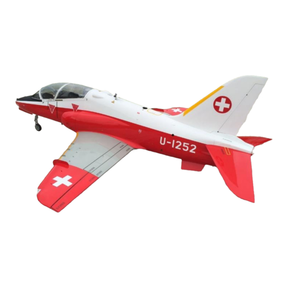
- Page 1 BAE Hawk MK 66 Instruction Manual F.W. 23/6/2015 Vers.1.0...
- Page 2 Thank you very much for purchasing the CARF Models Bae Hawk Mk 66. Before you get started building and setting-up your new aircraft, please make sure you have read this instruction manual, and understood it. If you have any questions, please don’t hesitate to contact your Rep, or CARF-Models directly.
- Page 3 Servo Choice: We strongly advise that you use the recommended high-torque digital metalgeared servos on all the main flight controls, and the milled plywood mounts are specifically designed for these. There are plenty of alternative servos available from many manufacturers. However, it is important that you measure the “height”...
- Page 4 Adhesives and Solvents: Not all types of glues are suited to working with composite parts. Here is a selection of what we normally use, and what we can truly recommend. Please don’t use inferior quality glues - you will end up with an inferior quality plane, that is not so strong or safe.
- Page 5 Accessories This list will help you chose the main additional items needed to finish your BAE Hawk Mk 66 1. Servos: 8 high quality Servos all the main control surfaces require a minimum of 20 kg torque such as JR8711 2.
- Page 6 Hardware List Material Name Piece For What Fin -Ruder Bag ALL THREAD M3 x 100 mm Ruder Plastic ball link M3 Ruder Plastic ball link M3 Smal Ruder Button head screw M3 x 15mm Ruder SHEET METAL SCREW 2.9*13 Ruder ALLEN SCREW M3 x15 Ruder Stop nut M 3...
- Page 7 Hardware List Retract Mount Bag Sheet metal screw 3.4 x 21 Landinggear mount Nose wheel stering Plastic ball link M3 Nose wheel stering Clevis Steel M 3 Nose wheel stering Allen Screw M3 x 16 mm Nose wheel stering ALL THREAD M3 x 30 mm Nose wheel stering Nut M 3 Nose wheel stering...
- Page 8 Hardware List Canopy Latch Fin Ruder Elevator Retract Front Gear Door Nose retract/Steering Fuselage joining Wing Main Gear Door Turbine mount Main Gear Door Intake...
- Page 9 Milled and Scale parts included in the kit Milled parts for Turbine - Ducting mounting Milled parts for elevator servo and trust tube support Milled parts for turbine equipment Milled part for Battery support Milled part for Powerbox switch Milled parts for Rc equipment Milled parts for hopper mounting Milled parts for Aileron Servo mounting Turbine –...
- Page 10 Milled and Scale parts included in the kit...
- Page 11 Fin - Rudder The servoplate is integral to the fin structure and the mounting holes are pre drilled for you. Before installing the servo arm, a 10 – 11 mm arm is the maximum size that will fit in the area. This length of arm will give you plenty of rudder thro.
- Page 12 Fin - Rudder Taking the 100 mm M3 threaded rod for the ruder pushrod, screw on the small M3 ball ink supplied to one end .For the next step you might find it easier to remove the rudder. This is done by simply pulling out the piano wire hinge from the bottom side of the ruder.
- Page 13 Fin - Rudder The fin assembly is secured to the fuselage using the supplied aluminum spar which you find is predrilled and fitted with a M3 captive nut for securing inside the rear of the fuselage. For the securing use the supplied M3 x 15 Using a dremel tool or similar cut an opening for the...
- Page 14 Elevator Bonding the mounts onto the CNC milled plate. Reinforce the bonding area with the supplied fiberglass band. Use epoxy resin only. Follow the steps 22 – 24. Once the resin is completely cured cut the excess fiberglass band Use the supplied 2.9 x 13mm sheet metal screws to mount the servos not screws supplied by the...
- Page 15 Elevator It is important that the two servos do not fight each other as the servo current draw is increased massively in this situation and will lead to early servo failure. After you adjust the linkage, cut the brass tube in the right length.
- Page 16 Elevator It is advisable at this point to fit the “bacon slicers" to the tail. These are not functional in any way on the model but are a scale feature and enhance the looks of the aircraft. Assemble the parts provided by gluing the 2 smaller side pieces for each unit to the top half.
- Page 17 Elevator Temporarily fix the tail in place on the aircraft and then tack the top and bottom half of the “bacon slicers” to the central tail block with cyano ensuring that there is no binding against the fuselage. Install the top hatch and again check there is no binding in this area.
- Page 18 Ventralfins Install the ventral fins in the rear of the model before final fit of the turbine and thrust tube assembly. The three tabs on each fin should be scuffed with a sheet of sandpaper before inserting on the pre cut slots in the bottom of the fuselage note the larger end of the fin is towards the front...
- Page 19 Turbine and Trust Tube Start by locating the 4 3mm milled plywood pieces. The two lower ones, which later contact the duct surface, need to be rounded as you see here. Trial fit until they sit flat on the duct mount surface.
- Page 20 Turbine and Trust Tube After the resin is cured the duct looks like shown on the photo. At this point the bypass can be measured for trimming. See how to mark and measure the area to be cut. Trim outside of the cut lines with a dremel or suitable rotary tool and tidy with files as appropriate.
- Page 21 Turbine and Trust Tube The rear of the tail cone of the turbine should be set at 45mm from the rear edge of the bypass. Ensure this measurement is carried out carefully. Once you have this position set, ensure the turbine is central within the pipe by observing through the rear end of the pipe.
- Page 22 Turbine and Trust Tube The turbine assembly can now be installed in the fuselage as a complete unit. Feed the pipe through the rear half of the fuselage and position so the bypass is centered on the bearers and at the rear the outer flange piece running at 45 degrees to the tailpipe is just within the rear of the fuselage.
- Page 23 Turbine and Trust Tube The rear of the thrust tube must be supported in some way to stop it from moving up / down or left / right. For the supporting use the supplied milled wood parts and glue – screw with 2.9 x 10mm on those formers in place.
- Page 24 Main and Hopper Tank CARF Models offer an optional molded Fiberglas or Kevlar fuel tank of 5.2 ltr capacity, which is installed in the fuselage on the CG . The tank is molded with a deeper rear trough to retain fuel towards the end of the tank and a blister in the front forward section for the vent to go up to allowing maximum fill capacity.
- Page 25 Main and Hopper Tank The tank is very easily installed in the airframe on to the pre-formed tray in the rear fuselage and secured with the Velcro straps provided. At this point you may wish to consider where you will want to place your turbine and radio ancillaries.
- Page 26 Hopper tank assembly Use a very short 6mm festo tube for the clunk line. The clunk is placed in the cubic center of the hopper, it is not designed to move at all. For the breather tube (connection to the main fuel tank) use a piece of tygon and cut a “V”...
- Page 27 Turbine electronic support the Skygate Hawk does not need all equipment to be as far forward as possible. We provide a wooden support for glue it on the main tank . Glue the wood parts together as shown in the picture. And place the turbine ancillaries on top of the fuel tank.
- Page 28 Canopy and Canopy Latch Slide the spring 1 cm over the brass tube. Make sure that the pin protrudes the fuselage surface and securely locks into the hole in the canopy frame. Use the white plastic sleeve to guide the steel wire. Cut the white tube approx.
- Page 29 Electronic support plate You are free to locate components for the support equipment wherever best meets your needs. We found on this model that fitting the Powerbox unit and air control systems in the rear fuselage just near the front and rear fuselage joint gave us the best solution.
- Page 30 Electronic support plate...
- Page 31 Aileron and Flap In the small wood pack you will find ply pieces to make up the aileron servo mounts. Clean the pieces with sandpaper and assemble with cyano making sure all joints are secure. For aileron actuation CARF Models recommend 25kg torque . Use a suitable aluminium servo arm.
- Page 32 Aileron and Flap The aileron servo linkage is made up using the M3 x 95mm threaded rod with 3mm ball link at one end and M3 aluminium clevis with 3mm pin at the servo end. Add a length of brass tube to the outside of the pushrod for extra strength if desired.
- Page 33 Aileron and Flap The flap surfaces are installed for you at the factory with beautiful scale hinging. What remains is for you to install the servo and linkage. CARF Models recommend a 25kg torque digital for the flap surfaces. We have used a aluminium arm at 38mm between Servo Center centers for the flap.
- Page 34 Front and Main Gear Doors The undercarriage set available for the BAE Hawk is specifically designed for this model and fits straight on to the mounting rails fitted in the wings and fuselage. The legs are supplied in plain aluminium finish for you to fit as is or paint according to the color scheme of your model.
- Page 35 Front and Main Gear Doors The mounts for the nose gear door rams are installed for you at the factory. Bolt the 2 rams to the mounts with M3 x 25 allen bolts with lock nuts. You might find the mounting holes in the rams are slightly large.
- Page 36 Front and Main retract The nose gear unit comes pre- assembled. In case you did not dis- assemble it for painting, ensure that all parts are secure and tight before installation. Attach the steering servo frame to the nose unit with the M3 dome head screw supplied and fit the servo using the M3 x 10 allen bolts supplied.
- Page 37 Front and Main retract You will find in your kit a pair of fiberglass strut covers for the main gear legs each in 2 halves. These covers are handed so make sure the cover set you select is correct for the gear leg you are working on.
- Page 38 Front and Main retract will fit well and then remove it again. Leave the first half to cure. Once the first half is securely bonded you can now add some balsa blocks to the inside of the first half. Shape the balsa blocks so they are in contact with both the leg and cover then glue in place with cyano.
- Page 39 Front and Main retract The main gear units fit on the rails installed in the wing. This is a crucial part of the build and some sanding of the rails may be necessary to get the required fit. It is also necessary to check that the retract mechanism does not foul the operation of the outer gear door.
- Page 40 Front and Main retract Fitting of the strut door and smaller outer wing door but some patience and time spent in this area will reward you with a well functioning nice looking system. The strut door is a double skinned part with scale detail on the inner skin.
- Page 41 Front and Main retract You will notice that the strut door when resting on the strut is proud of the wing surface. Begin by sanding through the inner door skin with a rotary tool at the points where the skin rests against the leg. Do this in small increments so you do not remove more material than is necessary.
- Page 42 Front and Main retract The small gear door has been fitted for you at the factory. However you must make up a linkage between this door and the strut. Begin by drilling and tapping a hole to M2 in the center of the front face of the retract trunnion.
- Page 43 Front and Main retract You can now locate the best place for fixing the mounting lug on the gear door by tacking it in place in the closed position and checking that it opens freely without fouling the strut door. Once you are happy with the location of the lug, secure in place with hysol or similar.
- Page 44 Canopy and inlay The canopy frame has all work done. It comes completely finished with all locks, tabs and slides. It fits perfectly on the fuselage. You just have to cut out the clear canopy and glue it into the frame. Roughly cut the front and rear of the canopy as molded, so that you can put it over the fuselage.
- Page 45 Canopy and inlay...
- Page 46 Canopy and inlay...
- Page 47 Canopy and inlay...
- Page 48 Canopy and inlay...
- Page 49 Canopy and inlay We provide in our kit a scale frame inlay. It will be very difficult to get it inside the canopy frame in one piece. So, simply cut it in two pieces and glue it in as shown on the photo.
- Page 50 Scale accessories and lights All those Naca inlets are clearly marked on the surface of the fuselage. Cut them out carefully and glue in the pre painted intakes which come with your kit. Cut them to fit and glue them from inside.
- Page 51 Tips and Hints about the Scale accessories and lights...
- Page 52 Tips and Hints about the Scale accessories and lights...
- Page 53 Tips and Hints about the Scale accessories and lights...
- Page 54 Tips and Hints about the Scale accessories and lights...
- Page 55 Tips and Hints about the Scale accessories and lights...
- Page 56 Tips and Hints about the Scale accessories and lights...
- Page 57 Tips and Hints about the Scale accessories and lights...
- Page 58 Wing Fences and Vortex generators Each wing also has a number of small vortex generators. You will see the relevant positions for the vortex generators on the wings. If you use a small pen for mark the position for the pins will make the task of drilling the holes easier.
- Page 59 Wing Fences and Vortex generators A set of wing fences and vortex generators is supplied in your kit and fitment is relatively easy. On each wing there is one large wing fence (see here in red) for the outboard of the wing, and 3 smaller fences (seen here in grey) to go further inboard.
- Page 60 Wing Fences and Vortex generators...
- Page 61 Balancing The final weight of you Bae Hawk MK 66 will vary depending on your equipment/turbine choice and the amount of scale detail you might choose to add. We guarantee that the plane can be build below 20 kg dry weight with our production cockpit, which can be ordered as an accessory.
-
Page 62: Control Movements
Control movements We have listed below the movements we used to fly the aircraft built for this manual. Different pilots sometimes prefer a different feel to the aircraft but you will find that using these movements as a starting point will give you safe and smooth operation. You can then adjust to suit your flying style.
Need help?
Do you have a question about the BAE Hawk MK 66 and is the answer not in the manual?
Questions and answers